

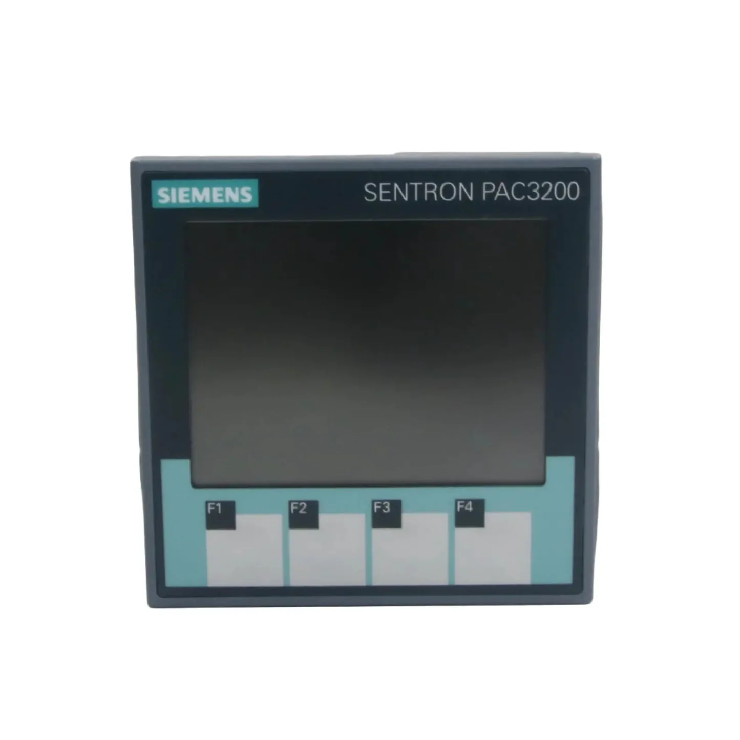
Siemens SENTRON PAC3200
Siemens
Dreiphasiges Messgerät für Spannung, Strom, Leistung, Leistungsfaktor, THD, Leistungsmittelwerte und Status über Modbus RTU oder TCP.
Überblick
Wichtige Messwerte
- Strang- und Außenleiterspannungen
- Strom je Phase und mittlerer Strom
- Wirk-, Blind- und Scheinleistung je Phase und gesamt
- Leistungsfaktor je Phase und gesamt
- THD von Spannung und Strom, Spannungs- und Stromunsymmetrie
- Frequenz
- Leistungsmittelwerte für Bezug und Lieferung
- Gerätestatus, Grenzwertverletzungen und Betriebsstunden
Anwendungsfälle
- Alarm, wenn Total Active Power die vertraglich vereinbarte Anschlussleistung eines Gebäudes überschreitet.
- Current L1, L2 und L3 sowie Current Unbalance überwachen, um eine überlastete Phase in einer Unterverteilung zu finden.
- THD Voltage und THD Current je Phase verfolgen, um Oberschwingungen durch Umrichter oder LED-Beleuchtung aufzuspüren.
- Demand Active Power Import über mehrere Wochen vergleichen, um Lastspitzenbegrenzung oder einen Tarifwechsel zu planen.
- Warnung ausgeben, wenn Device Status eine Spannungs- oder Stromüberlast meldet oder Limit Violations ungleich 0 ist.
- Total Power Factor protokollieren, um über eine Blindleistungskompensation zu entscheiden.
Installation
- 1Das Erweiterungsmodul PAC RS485 auf das PAC3200 stecken und die Klemmen A und B mit dem RS485-Anschluss Ihres ModbusCloud Gateways verbinden. Den Bus an beiden Enden terminieren.
- 2Am Gerät unter SETTINGS > RS485 MODULE die Werte ADDRESS (Standard 126), BAUD RATE (19200), SETTINGS (8N2) und PROTOCOL (MODBUS RTU) prüfen.
- 3Für Modbus TCP unter SETTINGS > COMMUNICATION IP-Adresse, Subnetz und Gateway eintragen und PROTOCOL von SEAbus TCP auf MODBUS TCP umstellen; das Gerät startet neu.
- 4In ModbusCloud ein Modbus-Gerät mit derselben Adresse und denselben seriellen Einstellungen (oder IP-Adresse und Port 502) anlegen und dieses Template importieren.
- 5Verbindung prüfen: Frequency sollte etwa 50 Hz und Voltage L1-N etwa 230 V in einem üblichen Niederspannungsnetz anzeigen.
Zu beachten
- Das Gerät antwortet nicht über RS485. Was sollte ich prüfen?
- Modbus RTU funktioniert nur mit gestecktem Erweiterungsmodul PAC RS485. Prüfen Sie die Moduleinstellungen unter SETTINGS > RS485 MODULE: Standard sind Adresse 126, 19200 Baud und 8N2, also zwei Stoppbits ohne Parität, was viele Tools nicht voreingestellt haben. Tauschen Sie danach A und B und prüfen Sie die Terminierung an beiden Busenden.
- Modbus TCP verbindet, aber auf Port 502 kommt keine Antwort.
- Die Ethernet-Schnittstelle arbeitet ab Werk mit SEAbus TCP. Stellen Sie PROTOCOL unter SETTINGS > COMMUNICATION auf MODBUS TCP und bestätigen Sie den Neustart. IP-Adresse, Subnetz und Gateway vor dem Umstellen eintragen.
- Warum erhalte ich eine Fehlermeldung oder unplausible Werte?
- Jeder Messwert ist ein Float in zwei Registern. Das PAC3200 meldet einen Fehler, wenn ein Lesezugriff im zweiten Register eines Werts beginnt, und eine verschobene Adresse liefert Unsinn. Verwenden Sie die Adressen genau wie in diesem Template (Voltage L1-N auf 1, Total Active Power auf 65), High-Word zuerst.
- Wo sind die kWh-Zähler?
- Siemens legt die Energiezähler (ab Offset 801) als 64-Bit-Double ab. ModbusCloud-Templates enthalten nur 16- und 32-Bit-Werte, deshalb fehlen sie in diesem Template. Demand Active Power Import und die Leistungswerte sind enthalten.
- Ströme und Leistungen sind viel zu niedrig oder zu hoch.
- Das PAC3200 rechnet die Wandlerverhältnisse selbst ein. Prüfen Sie Primary Current und Secondary Current, bei Spannungswandlern auch Primary Voltage und Secondary Voltage, gegen die eingebauten Wandler. Connection Type muss zur Verdrahtung passen, zum Beispiel 3P4W für ein Vierleiternetz.
- Mehrere Geräte an einem Bus antworten zufällig.
- Jedes Gerät an der RS485-Leitung braucht eine eigene Adresse. Alle Module PAC RS485 werden mit Adresse 126 ausgeliefert. Vergeben Sie deshalb jedem Messgerät eine eindeutige Adresse von 1 bis 126, bevor Sie die Geräte zusammenschalten.
Register (61)
61 lesen / 0 schreiben
| Name | Adresse | Funktion | Typ | Einheit | Zugriff |
|---|---|---|---|---|---|
Voltage L1-N Phase-to-neutral voltage L1-N in volts, IEEE 754 float. Manual name: Voltage Va-n. | ••• | ••• | ••• | V | R |
Voltage L2-N Phase-to-neutral voltage L2-N in volts, IEEE 754 float. Manual name: Voltage Vb-n. | ••• | ••• | ••• | V | R |
Voltage L3-N Phase-to-neutral voltage L3-N in volts, IEEE 754 float. Manual name: Voltage Vc-n. | ••• | ••• | ••• | V | R |
Voltage L1-L2 Phase-to-phase voltage L1-L2 in volts. Manual name: Voltage Va-b. | ••• | ••• | ••• | V | R |
Voltage L2-L3 Phase-to-phase voltage L2-L3 in volts. Manual name: Voltage Vb-c. | ••• | ••• | ••• | V | R |
Voltage L3-L1 Phase-to-phase voltage L3-L1 in volts. Manual name: Voltage Vc-a. | ••• | ••• | ••• | V | R |
Current L1 Current in phase L1 in amperes. Manual name: Current a. | ••• | ••• | ••• | A | R |
Current L2 Current in phase L2 in amperes. Manual name: Current b. | ••• | ••• | ••• | A | R |
Current L3 Current in phase L3 in amperes. Manual name: Current c. | ••• | ••• | ••• | A | R |
Active Power L1 Active power in phase L1 in watts. Manual name: Active Power a. | ••• | ••• | ••• | W | R |
Active Power L2 Active power in phase L2 in watts. Manual name: Active Power b. | ••• | ••• | ••• | W | R |
Active Power L3 Active power in phase L3 in watts. Manual name: Active Power c. | ••• | ••• | ••• | W | R |
Total Active Power Sum of the active power of all phases in watts. Manual name: Total Active Power. | ••• | ••• | ••• | W | R |
Total Reactive Power Sum of the reactive power of all phases in var. Manual name: Total Reactive Power. | ••• | ••• | ••• | var | R |
Total Apparent Power Sum of the apparent power of all phases in VA. Manual name: Total Apparent Power. | ••• | ••• | ••• | VA | R |
Total Power Factor Power factor over all phases. Manual name: Total Power Factor. | ••• | ••• | ••• | R | |
Frequency Mains frequency in hertz, range 45 to 65 Hz. Manual name: Frequency. | ••• | ••• | ••• | Hz | R |
Average Voltage L-N Average of the three phase-to-neutral voltages in volts. Manual name: Average Voltage Vph-n. | ••• | ••• | ••• | V | R |
Average Voltage L-L Average of the three phase-to-phase voltages in volts. Manual name: Average Voltage Vph-ph. | ••• | ••• | ••• | V | R |
Average Current Average of the three phase currents in amperes. Manual name: Average Current. | ••• | ••• | ••• | A | R |
Reactive Power L1 Reactive power in phase L1 in var. Manual name: Reactive Power a. | ••• | ••• | ••• | var | R |
Reactive Power L2 Reactive power in phase L2 in var. Manual name: Reactive Power b. | ••• | ••• | ••• | var | R |
Reactive Power L3 Reactive power in phase L3 in var. Manual name: Reactive Power c. | ••• | ••• | ••• | var | R |
Apparent Power L1 Apparent power in phase L1 in VA. Manual name: Apparent Power a. | ••• | ••• | ••• | VA | R |
Apparent Power L2 Apparent power in phase L2 in VA. Manual name: Apparent Power b. | ••• | ••• | ••• | VA | R |
Apparent Power L3 Apparent power in phase L3 in VA. Manual name: Apparent Power c. | ••• | ••• | ••• | VA | R |
Power Factor L1 Power factor of phase L1, range 0 to 1 per the manual. Manual name: Power Factor a. | ••• | ••• | ••• | R | |
Power Factor L2 Power factor of phase L2, range 0 to 1 per the manual. Manual name: Power Factor b. | ••• | ••• | ••• | R | |
Power Factor L3 Power factor of phase L3, range 0 to 1 per the manual. Manual name: Power Factor c. | ••• | ••• | ••• | R | |
THD Voltage L1 Total harmonic distortion (THD-R) of the voltage in phase L1, 0 to 100 %. Manual name: THD-R Voltage a. | ••• | ••• | ••• | % | R |
THD Voltage L2 Total harmonic distortion (THD-R) of the voltage in phase L2, 0 to 100 %. Manual name: THD-R Voltage b. | ••• | ••• | ••• | % | R |
THD Voltage L3 Total harmonic distortion (THD-R) of the voltage in phase L3, 0 to 100 %. Manual name: THD-R Voltage c. | ••• | ••• | ••• | % | R |
THD Current L1 Total harmonic distortion (THD-R) of the current in phase L1, 0 to 100 %. Manual name: THD-R Current a. | ••• | ••• | ••• | % | R |
THD Current L2 Total harmonic distortion (THD-R) of the current in phase L2, 0 to 100 %. Manual name: THD-R Current b. | ••• | ••• | ••• | % | R |
THD Current L3 Total harmonic distortion (THD-R) of the current in phase L3, 0 to 100 %. Manual name: THD-R Current c. | ••• | ••• | ••• | % | R |
Voltage Unbalance Amplitude unbalance of the voltage, 0 to 100 %. Manual name: Amplitude Unbalance - Voltage. | ••• | ••• | ••• | % | R |
Current Unbalance Amplitude unbalance of the current, 0 to 200 %. Manual name: Amplitude Unbalance - Current. | ••• | ••• | ••• | % | R |
Max Total Active Power Highest total active power since the maximum values were last reset, in watts. Manual name: Max. Total Active Power. | ••• | ••• | ••• | W | R |
Min Total Active Power Lowest total active power since the minimum values were last reset, in watts. Manual name: Min. Total Active Power. | ••• | ••• | ••• | W | R |
Demand Active Power Import Average active power drawn over the last completed demand period, in watts. Manual name: Demand Active Power - Import. | ••• | ••• | ••• | W | R |
Demand Reactive Power Import Average reactive power drawn over the last completed demand period, in var. Manual name: Demand Reactive Power - Import. | ••• | ••• | ••• | var | R |
Demand Active Power Export Average active power delivered over the last completed demand period, in watts. Manual name: Demand Active Power - Export. | ••• | ••• | ••• | W | R |
Demand Reactive Power Export Average reactive power delivered over the last completed demand period, in var. Manual name: Demand Reactive Power - Export. | ••• | ••• | ••• | var | R |
Max Active Power In Period Highest active power reading during the demand period, in watts. Manual name: Maximum Active Power Reading during the period. | ••• | ••• | ••• | W | R |
Demand Period Length Length of the demand period in seconds (set in minutes, 1 to 60, under Demand Period). Manual name: Demand Period. | ••• | ••• | ••• | s | R |
Time Since Demand Period Start Seconds elapsed since the start of the active demand period. Manual name: Time Since Start of the active demand period. | ••• | ••• | ••• | s | R |
Device Status Bitfield. 0x08000000 = current overload, 0x04000000 = voltage overload, 0x02000000 = configuration menu active, 0x01000000 = no sync pulse, 0x00000800 = device restarted, 0x00000200 = limit violation stored. 0 = no flag set. | ••• | ••• | ••• | R | |
Limit Violations Bitfield of the six programmable limits: 0x01 = limit 0 up to 0x20 = limit 5, 0x01000000 = limit logic. A set bit means the limit is violated. 0 = no violation. | ••• | ••• | ••• | R | |
Digital Input Status State of digital input 0 (bit mask 0x00000001). Manual name: Status of the digital inputs. | ••• | ••• | ••• | R | |
Digital Output Status State of digital output 0 (bit mask 0x00000001). Manual name: Status of the digital outputs. | ••• | ••• | ••• | R | |
Active Tariff Tariff that the energy counters are currently counting in: 0 = tariff 1, 1 = tariff 2. Manual name: Active Tariff. | ••• | ••• | ••• | R | |
Working Hours Counter Operating time counter in seconds, 0 to 999999999. Read only in this template although the manual allows writing it. Manual name: Working hours counter. | ••• | ••• | ••• | s | R |
Universal Counter Counts pulses or events from the source set under Universal counter source (digital input, digital output or a limit), 0 to 999999999. | ••• | ••• | ••• | R | |
Relevant Parameter Changes Number of changes to parameters that affect the measurement. Manual name: Relevant Parameter Changes Counter. | ••• | ••• | ••• | R | |
All Parameter Changes Number of changes to any device parameter. Manual name: Counter All Parameter Changes. | ••• | ••• | ••• | R | |
Connection Type Configured wiring: 0 = 3P4W, 1 = 3P3W, 2 = 3P4WB, 3 = 3P3WB, 4 = 1P2W. Read only in this template. Manual name: Connection type. | ••• | ••• | ••• | R | |
Primary Current Configured CT primary current, 1 to 99999 A. Read only in this template. Manual name: Primary current. | ••• | ••• | ••• | A | R |
Secondary Current Configured CT secondary current, 1 A or 5 A. Read only in this template. Manual name: Secondary current. | ••• | ••• | ••• | A | R |
Primary Voltage Configured VT primary voltage, 1 to 999999 V, only used when voltage transformers are enabled. Read only in this template. | ••• | ••• | ••• | V | R |
Secondary Voltage Configured VT secondary voltage, 1 to 690 V, only used when voltage transformers are enabled. Read only in this template. | ••• | ••• | ••• | V | R |
Demand Period Setting Configured demand period in minutes, 1 to 60. Read only in this template. Manual name: Demand Period. | ••• | ••• | ••• | min | R |
Register werden geladen…
Siemens SENTRON PAC3200 aus der Ferne auslesen
Wir spielen die Templates auf das Gateway und richten Ihr Portal ein, Sie schließen es beim Kunden an. Beschreiben Sie kurz, was Sie brauchen, dann schicken wir Ihnen ein Angebot.
Ab €295 + €149/Jahr.
Lieber selbst konfigurieren? Gateway im Shop bestellen·Oder zuerst die Live-Demo ansehen
Weitere Siemens-Vorlagen

Siemens Junelight Smart Battery (battery)
Siemens
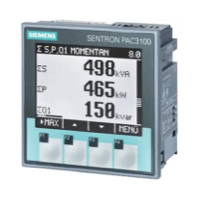
Siemens Sentron PAC3100 Power meter 3 phase
Siemens
Reads 3-phase power metering data from a Siemens Sentron PAC3100.
Siemens 7KT1665 (grid)
Siemens
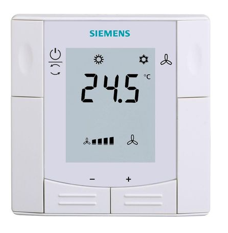
Siemens RDF660MB
Siemens
Controls a Siemens room thermostat via Modbus RTU
Siemens Sentron PAC 2200
Siemens
Monitors three-phase energy metering via Modbus TCP on Siemens Sentron PAC 2200.

Siemens RDF302
Siemens
Controls a Siemens room thermostat via Modbus RTU
Weitere RTU-Vorlagen

Alnor HRU
Alnor Systemy Wentylacji Sp. z o. o.
Controls and monitors Alnor heat recovery ventilation units via Modbus RTU.

connecdoor.controller
connecdoor
Controls and monitors smart door access points via RS485
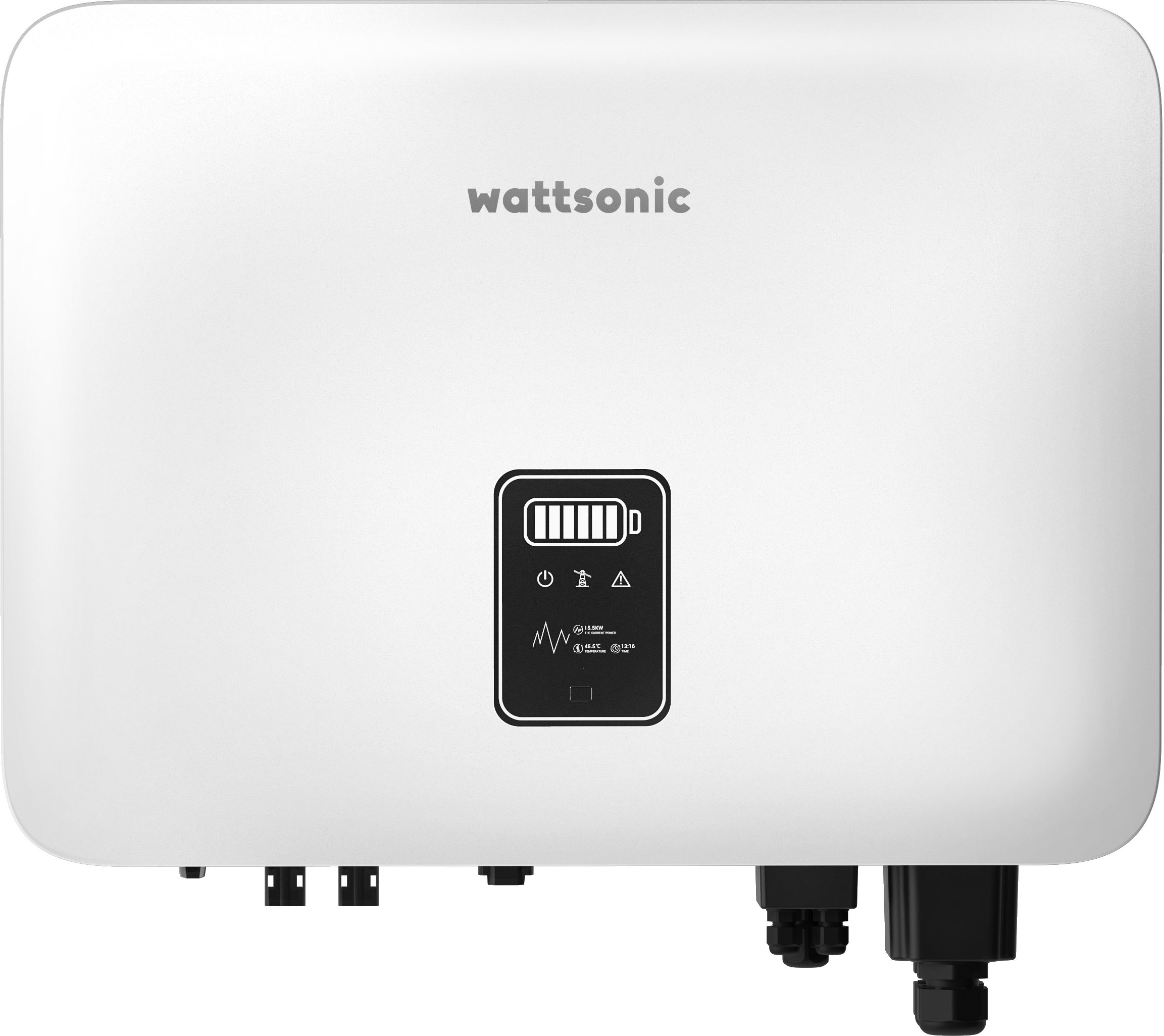
Wattsonic - Schmachtl Sun Energy Box
Wattsonic
Monitors Schmachtl Wattsonic hybrid inverter via Modbus RTU

Alnor HRU-P
Alnor Systemy Wentylacji Sp. z o. o.
Controls Alnor HRU-P heat recovery ventilation units via Modbus RTU.

Heidelberg Wallbox Energy Control
AMPERFIED GmbH
Controls and monitors Heidelberg Wallbox Energy Control EV charger via Modbus RTU.
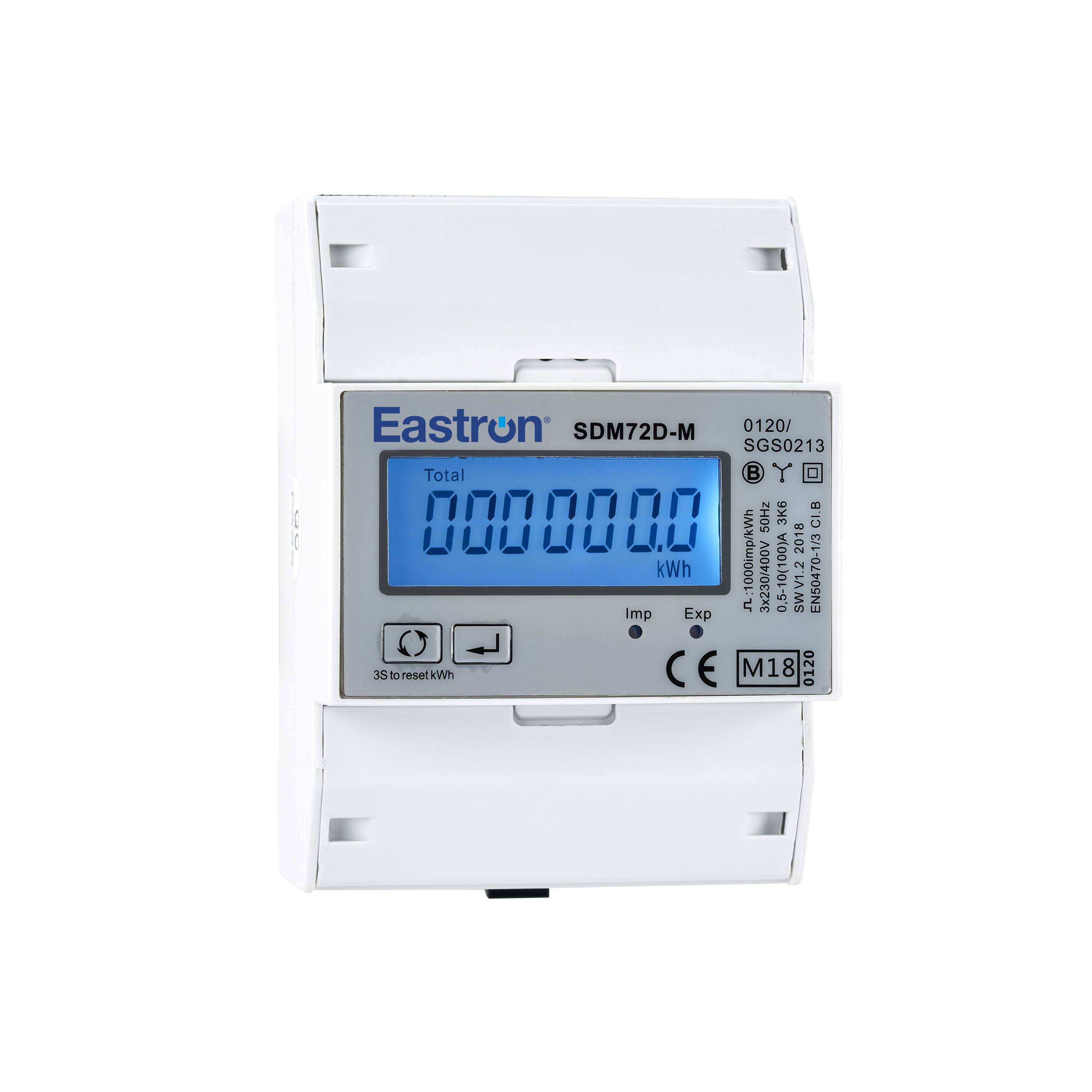
Eastron SDM72D-M
Eastron
Reads energy metering values from an Eastron SDM72D-M three-phase meter.