Modbus RTU explained: a complete guide for installers (2026)
Modbus RTU explained for installers. Frame structure, RS485 wiring, function codes, troubleshooting, and what the EPBD obligation from 2026 means.
Modbus RTU has been the workhorse of industrial protocols since 1979, and in 2026 it remains the first choice at the device level in HVAC, heat pumps, energy meters and refrigeration. Yet most installers stumble on the same three obstacles: the frame structure, the RS485 wiring, and the difference between function codes and register types. This guide sorts those three out.
You will learn how a Modbus RTU frame is built, how to lay out an RS485 daisy chain mechanically and electrically, which function codes you actually need on the job, and how to read a holding register byte by byte. By the end you will also know what the new EPBD obligation from 1 January 2026 means for your projects. Written for installers, not for software developers.
Key takeaways
- Modbus RTU sends five fixed fields over RS485: slave address, function code, data, CRC, then a silent interval of 3.5 character times.
- A single RS485 segment carries up to 32 electrical loads and 247 logical slave addresses, with 1,200 m total length as the upper limit.
- From 1 January 2026 the EPBD recast (EU 2024/1275) lowers the threshold for mandatory building automation from 290 kW to 70 kW, and Modbus RTU is often the underlying transport.
What is Modbus RTU exactly?
Modbus RTU is a serial variant of the Modbus protocol that sends binary frames over RS485 (or RS232) and uses CRC-16 for error detection. RTU stands for Remote Terminal Unit, a term that goes back to the PLC world where Modbus was introduced by Modicon in 1979. The application layer (function codes and register addresses) is identical to Modbus TCP and Modbus ASCII, only the transport differs.
According to the Modbus Application Protocol V1.1b3 specification, maintained by the Modbus Organization, RTU is the most common form of Modbus over a serial line. You recognise a Modbus RTU installation by three terminals on a connector block (A, B, GND) and a daisy-chain topology where up to 32 devices follow each other on a single bus.
In 2026 Modbus RTU still sits inside virtually every new heat pump, energy meter and refrigeration controller. Higher layers like BACnet, KNX or OPC UA take over supervision, but at the layer where you, as an installer, pull cable and make first contact, RTU remains the standard. For a broader explanation of what Modbus is and why it remains dominant, see our complete Modbus guide.
How a Modbus RTU frame is structured
A Modbus RTU frame always has five fields in this fixed order: slave address, function code, data, CRC, and then a silent interval of 3.5 character times. The order never changes; only the length of the data field varies per function code.
The slave address is one byte with a value between 1 and 247. Address 0 is reserved for broadcast messages to which slaves do not reply. The function code tells the slave what the master wants to do, for example 0x03 to read holding registers. The data field carries the parameters of the request or response and is variable in length. The CRC-16 is a 2-byte checksum that the slave (and master) computes over all preceding bytes, with polynomial 0xA001 as defined in the Modbus over Serial Line Specification V1.02, section 2.5.1.2.
The silent interval of 3.5 character times is what installers often overlook but which makes a real difference in practice. At baud rates up to 19,200 baud the interval scales with the baud rate (at 9,600 baud it is 3.65 ms), above 19,200 baud it is fixed at 1.75 ms. Slaves use the interval to detect where one frame ends and the next begins. If your polling tool keeps the interval too short, you will see random timeout errors.
RS485 physical layer in practice
Every RS485 device exposes three terminals: A (non-inverting signal), B (inverting signal) and GND (common ground). The combination of A and B forms the differential pair that carries the signal. GND ensures that all devices share the same voltage reference.
In practice you see three classic mistakes. The first is A and B swapped, which most devices tolerate because some manufacturers label A and B opposite to the TIA-485-A convention. The second is GND forgotten, which works until devices sit on different mains phases and the voltage difference grows. The third is power cables run too close to the RS485 cable, which over a 50 m run can already inject enough noise to trigger CRC errors.
For a clean installation, separate ELV signal cables (RS485 included) from LV power cables by at least 200 mm parallel run distance, or route them through a dedicated trunking. Use shielded twisted-pair cable, ideally Belden 9841 or an equivalent Cat 5e, with ferrite cores on critical points. The relevant guidance comes from the LV installation standards aligned with IEC 60364-5-52 (separation of circuits).
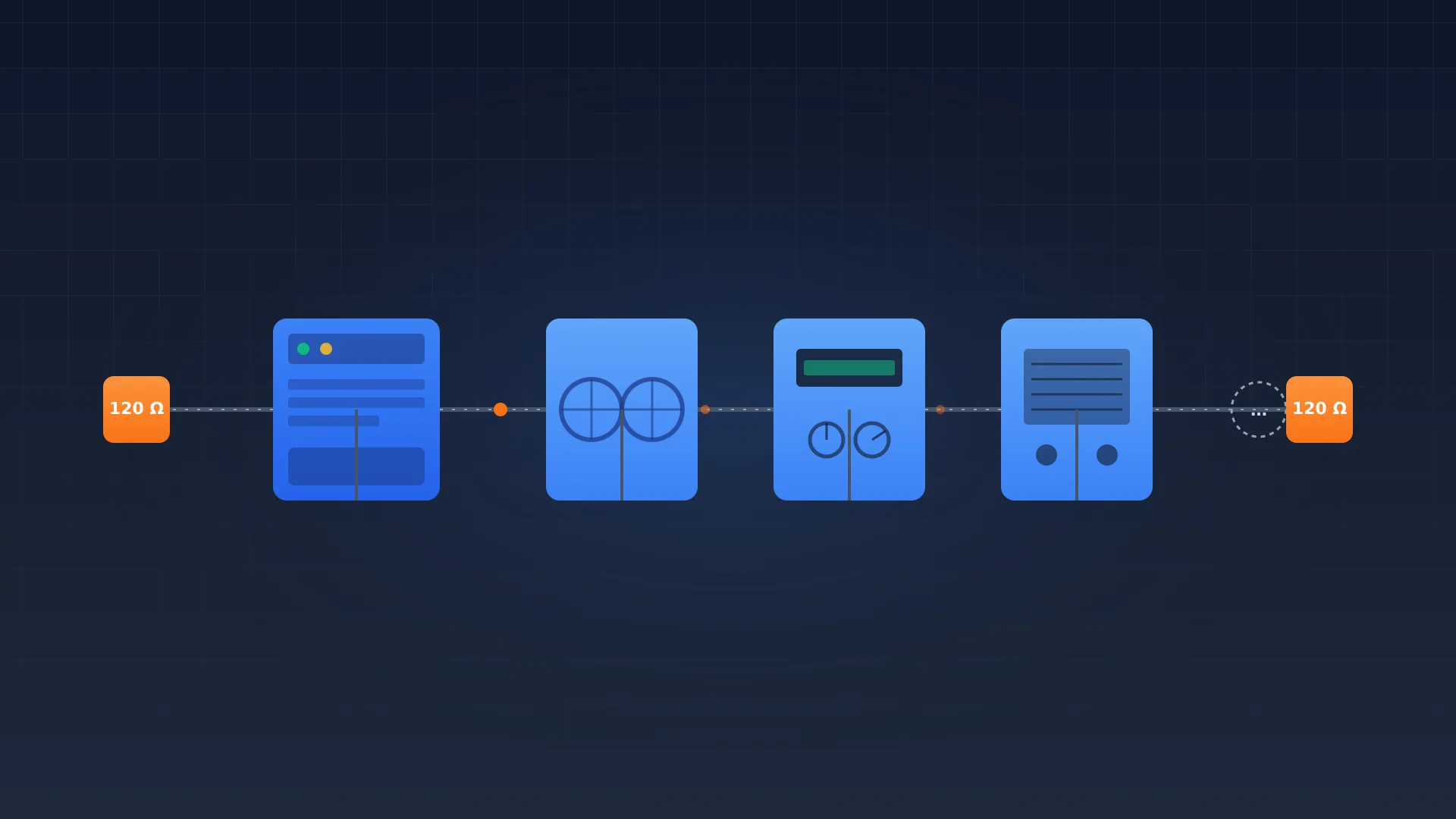
Termination: 120 ohms at both ends
Place a 120 ohm termination resistor at both physical ends of the daisy chain, never in the middle. That is the entire rule. If installers forget one terminator, reflections distort the signal and trigger CRC errors. If they fit three or four, the resistors pull in parallel below the line driver IC's minimum load and the signal collapses.
Many modern gateways and some slaves have built-in 120 ohm termination via a DIP switch or jumper. Always check that termination is enabled at the right places and that it is not accidentally active in the middle of the bus.
Slave addresses, baud rate and parity
Every slave on the bus needs a unique slave address between 1 and 247. For energy meters you typically start at 1 and number sequentially; for heat pumps the address is usually set in the service menu or via DIP switches. Addresses travel in every RTU frame, so duplicate addresses cause immediate collisions and you see two slaves answer simultaneously.
You pick the baud rate per bus, not per slave: every device on the same physical RS485 line must use the same baud rate. In 2026 the common choices are 9,600, 19,200 and 38,400 baud. Standard ModbusCloud projects run at 9,600 baud 8N1 because that combination is the most stable across a 200 to 1,200 m daisy chain. Higher baud rates shorten the polling cycle but make the installation more sensitive to cable quality and reflections.
Parity is the second half of the 8N1 jargon. 8N1 means 8 data bits, no parity, 1 stop bit. The Modbus over Serial Line Specification also defines 8E1 (even parity, 1 stop bit) and 8O1 (odd parity, 1 stop bit). Some older devices require 8E1, so always check the datasheet before commissioning a bus.
Function codes and register types that matter
A function code tells the slave what the master wants to do. Of the 24 codes defined in the specification, in HVAC and refrigeration you mostly use seven.
| FC | Name | Use | Who uses it |
|---|---|---|---|
| 01 | Read Coils | Read on/off relay state | Refrigeration, lighting |
| 02 | Read Discrete Inputs | Read alarm and status contacts | Alarm monitoring |
| 03 | Read Holding Registers | Read setpoints and config | Dominant FC in HVAC |
| 04 | Read Input Registers | Read measured values | Energy meters, PV |
| 05 | Write Single Coil | Switch a relay | Manual control |
| 06 | Write Single Register | Write a setpoint | Setpoint change |
| 16 | Write Multiple Registers | Write several registers | Bulk configuration |
The four register types differ in access and in the Modicon prefix you often see in datasheets. Coils (0x prefix) are 1 bit read-write, discrete inputs (1x) are 1 bit read-only, input registers (3x) are 16 bit read-only, holding registers (4x) are 16 bit read-write. In practice 80 percent of what you read sits in holding (4x) and input (3x) registers.
A 32-bit float spread across two 16-bit registers is common in energy meters: always check the datasheet for whether the manufacturer sends high word first (big endian) or low word first (little endian). Eastron, Carlo Gavazzi and most European meters use big endian; some Asian brands do the opposite.
Worked example: read a holding register with FC03
Suppose you read voltage L1 from an Eastron SDM630 at register address 0x0000 (two registers because the value is a 32-bit float). The request is exactly 8 bytes long.
| Byte | Content | Meaning |
|---|---|---|
| 0 | 0x01 | slave address 1 |
| 1 | 0x03 | function code 03 (read holding registers) |
| 2-3 | 0x00 0x00 | start register address |
| 4-5 | 0x00 0x02 | number of registers (2) |
| 6-7 | 0xC4 0x0B | CRC-16 |
The slave responds with 9 bytes: slave address (1B), function code (1B), byte count (1B = 4), 4 data bytes (the float), and 2 bytes CRC. At 9,600 baud the full cycle takes around 20 ms. With a 1-second polling interval you can comfortably interrogate over 30 slaves in sequence without overlap.
Troubleshooting: five common RTU problems
When a bus does not behave, walk through these five in order before looking deeper.
| Symptom | Probable cause | Fix |
|---|---|---|
| No response from one specific device | Wrong or duplicated slave address | Check DIP switches or menu setting; a logger reveals bus traffic |
| Random CRC errors across the whole bus | Termination forgotten or doubled | With power off, measure between A and B; should read 60 ohms (two 120 ohm in parallel) |
| Works on one device, fails with several | A and B swapped on a tap | Inspect every connection, A to A and B to B |
| Random timeouts at high polling | Silent interval too short | Increase polling interval to at least 2x frame time plus 3.5 character times |
| Works during the day, fails at night | Power cable couples into RS485 | Separate cables by at least 200 mm or run them in dedicated trunking |
For stubborn problems a serial protocol logger like a USB-RS485 adapter with Wireshark or a Modbus scanner is invaluable. It shows byte-by-byte what request the master sends and what response (or lack of one) comes back.
Modbus RTU and the 2026 EPBD obligation
From 1 January 2026 the EPBD recast (EU 2024/1275), Article 14, lowers the threshold for mandatory building automation and monitoring (BACS) from 290 kW to 70 kW effective heating or cooling output in non-residential buildings. A large group of mid-size buildings now falls under the obligation: offices around 1,000 m², secondary schools, smaller hospitals.
For an installer this means: practically every new heat pump above 70 kW must deliver a digital data point to a higher-level system, and Modbus RTU is often the underlying transport. According to the EHPA Market Report 2025, around 60 percent of new heat pump installations across Europe ship with a Modbus or BACnet interface. For energy meters, where Eastron, Janitza and Carlo Gavazzi dominate the European market, the share is higher still.
In practice you build the chain with a gateway that polls the Modbus RTU bus and forwards the data over MQTT or an API to a monitoring platform. That meets the Class B requirement from DIN EN ISO 52120-1 the EPBD references: continuous data acquisition per technical installation. See how a ModbusCloud Gateway implements such a chain.
What is the difference between Modbus RTU and Modbus TCP?
Modbus RTU sends binary frames over a serial RS485 or RS232 connection with CRC-16 error checking. Modbus TCP sends the same function codes inside a TCP/IP packet with an MBAP header on port 502 over Ethernet. The application layer is identical; only the transport differs.
How many slaves can a Modbus RTU bus support?
Logically Modbus RTU supports 247 slave addresses plus broadcast address 0. Electrically RS485 limits a segment to 32 standard loads. If you need more devices, split the bus with repeaters or use a second gateway port.
What baud rate is common for Modbus RTU?
9,600 baud 8N1 is the most stable default in European HVAC and refrigeration. 19,200 and 38,400 baud appear where polling cycles must be shorter, but they are more sensitive to cable quality and reflections. Always start at 9,600 and step up once everything runs.
Do you need termination resistors on Modbus RTU?
Yes, place a 120 ohm termination resistor at both physical ends of the daisy chain. Never in the middle, as the resistors then pull in parallel below the minimum load of the line driver IC and the signal collapses.
How long can a Modbus RTU cable run?
The TIA/EIA-485-A standard allows up to 1,200 m at 9,600 baud with twisted-pair cable. At 38,400 baud the limit drops to roughly 600 m. For stable installations, keep a 30 percent margin on these figures.
What does 8N1, 8E1 and 8O1 mean?
These shorthand codes describe the serial frame setting: 8 data bits, parity (None, Even or Odd), and 1 stop bit. 8N1 is the Modbus default. 8E1 is required by some older devices. Every device on a bus must share the same setting.
Ready to set up monitoring that meets the 2026 EPBD obligation? A ModbusCloud Gateway reads the Modbus RTU bus and forwards every data point securely to a central dashboard. See how a complete chain looks and what it means for your projects.
Ready to get started?
Order the ModbusCloud Gateway and start monitoring your installations within 5 minutes.
View the gateway