Modbus alerts: a complete setup guide for installers (2026)
Set up Modbus alerts without alarm storm. Thresholds, hysteresis, three-poll rule, channels (email, SMS, Teams), audit trail for EU F-gas Regulation 517/2014 and ISO 50001. Practical for installers.
Modbus alerts are automated notifications that fire when a register crosses a threshold or a device stops responding. For installers they decide whether you find out about a heat pump trip at 02:00 by phone, or whether you get a timely push you can act on. The bottleneck is not setting a threshold; it is preventing alarm storm and routing each severity to the right channel.
You will learn here how to set thresholds, hysteresis, and debounce; how to detect communication loss with the three-poll rule; how to map severity classes to channels (email, SMS, Microsoft Teams); and how to keep the audit trail for EU F-gas Regulation 517/2014 and ISO 50001 monitoring. Aimed at HVAC installers, refrigeration technicians, and integrators who monitor Modbus devices remotely.
Key takeaways
- Use 5 to 10 percent hysteresis around your threshold, with debounce of 30 to 120 seconds for temperature and 5 to 10 seconds for pressure.
- Treat a Modbus device as offline only after three consecutive failed polls, never after a single CRC error.
- Route severities to different channels: info on dashboard, warning by email, alarm and critical also by SMS or Teams.
What is a Modbus alert?
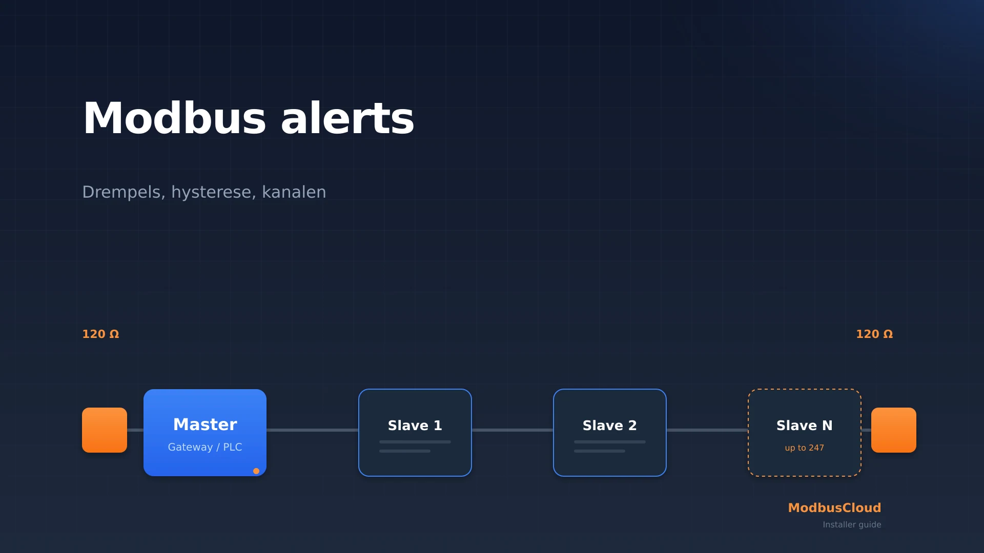
A Modbus alert is a notification raised by the master, edge gateway, or cloud platform when a polled register value matches a predefined rule. Modbus has no native push mechanism. A slave cannot send an alarm on its own; the master must poll and evaluate the rule itself (Modbus Organization Specification V1.1b3). The alert engine therefore always lives upstream of Modbus, in a PLC, in the ModbusCloud Gateway, or in a cloud platform.
In practice you deal with seven alert types:
| Type | Fires when | Example |
|---|---|---|
| Threshold (high/low) | Value crosses a fixed limit | Flow temperature > 65 °C |
| Hysteresis | Separate set/reset values | Set 65 °C, reset 63 °C |
| Rate of change | Value moves too fast | Compressor speed > 200 rpm/s |
| Discrete input (coil) | Fault contact closes | High-pressure switch |
| Status register flag | Vendor code in holding register | Nibe register 45001 "Alarm number" |
| Communication loss | Three failed polls in a row | Device offline |
| Calculated (virtual) | Derived from multiple registers | Evaporator ΔT |
Modbus exception codes (function response byte set to 0x80 plus an exception code 1 to 11, see the Modbus Organization specification) are protocol-level errors, not application alarms. Do not rely on them for process alarming; they help the master understand that the request itself failed.
For protocol fundamentals see the complete Modbus guide and the explanations of Modbus RTU and Modbus TCP.
What you need before you start
A working alert chain requires three hardware and three software choices. Skip none of them: a wrong choice upstream costs an hour of troubleshooting downstream.
- A polling master: a PLC with IoT licence, a SCADA, a Home Assistant instance, or an edge gateway such as the ModbusCloud Gateway.
- A stable physical layer: for RS485 a correctly terminated bus with 120 Ω at both ends and clearance from 230 V wiring per IEC 60364-4-44. For TCP a static IP per Modbus device.
- Threshold values from vendor documentation: note the healthy range and the fault range for every register you alarm on.
- A notification channel per severity: at minimum email; ideally also SMS and a Microsoft Teams incoming webhook.
- A documented snooze route: an installer must be able to suppress an alert during maintenance without deleting the rule.
- Audit trail storage: for refrigeration a minimum 5-year retention per Article 6 of EU Regulation 517/2014.
How to set a threshold alarm
A threshold alarm compares the polled register value with a limit. As soon as the value crosses above (high) or below (low) the limit, the master evaluates the rule. In ModbusCloud you configure this per device template: choose the register, the operator (>, <, ==, !=, in range, out of range), the value, and the severity.
For a Vaillant geoTHERM heat pump with flow temperature register 0x008C (Modbus TCP via the VR 920 interface) a typical set looks like this:
| Register | Type | Threshold | Severity | Channel |
|---|---|---|---|---|
| 0x008C flow temperature | high | > 65 °C | warning | |
| 0x008C flow temperature | high | > 75 °C | alarm | SMS + Teams |
| 0x4001 SG Ready mode | equals | 1 (locked) | info | dashboard |
| 0x0050 fault code | not equals | 0 | alarm | SMS + Teams |
Always work from the installer manual, never from an internet source. Vaillant publishes the official registers via pro.vaillant.com behind a login; Daikin publishes via its Stand Alone Modbus Interface Manual. According to a 2025 ARC Advisory Group report, a mistyped register address causes roughly 18 percent of all first-deployment problems with Modbus monitoring.
How to prevent alarm storm with hysteresis and debounce
A raw threshold without hysteresis chatters around the boundary: the value wobbles above and below 65 °C in a minute and you get twenty notifications. The three rules are hysteresis, debounce, and cooldown. EEMUA Publication 191 (Alarm Systems guide) is the international reference and gives a target of no more than 1 to 2 alarms per operator per 10 minutes during normal operation.
- Hysteresis (deadband): separate set and reset thresholds. Typical 5 to 10 percent of the threshold magnitude. For 65 °C that is 3 to 6 °C; pick 2 °C if you have a precise sensor.
- Debounce: the value must stay above the set threshold for N seconds before the alarm fires. For temperatures 30 to 120 seconds. For pressures 5 to 10 seconds. For PV power or EV charging current keep it at 5 seconds.
- Cooldown: minimum interval between repeated notifications of the same alert. Default 15 minutes. For maintenance use a separate snooze of 4 or 24 hours.
How to detect that a Modbus device is offline
A single failed poll does not mean the device is offline. A short CRC error on RS485, a brief Wi-Fi drop on a Modbus TCP gateway, or a Modbus response that runs into a timeout are normal events. The three-poll rule filters this noise out.
Concrete settings per device class:
| Device | Polling interval | Timeout per poll | Offline after |
|---|---|---|---|
| Heat pump | 60 s | 2 s | 3 misses (3 min) |
| Energy meter | 30 s | 1 s | 3 misses (90 s) |
| Refrigeration controller | 30 s | 1 s | 3 misses (90 s) |
| PV inverter | 15 s | 2 s | 3 misses (45 s) |
| EV charger | 10 s | 1 s | 3 misses (30 s) |
A higher polling rate means more 4G data, more load on the RS485 bus, and less room for other slaves. For alarming, 30 seconds satisfies 80 percent of installer cases. The ModbusCloud Gateway polls at 60 seconds by default and is configurable down to 5 seconds through the dashboard.
Which channels to route per severity
Not every notification belongs on SMS. An installer who gets every status change on their phone turns off the channel within two weeks. EEMUA Publication 191 recommends a maximum of 1 to 2 alarms per operator per 10 minutes during normal operation. Translate that to installer scale by routing different severities to different channels.
- Information: dashboard only. A SG Ready mode change, a maintenance reminder.
- Warning: email to the installer inbox. Flow temperature 5 °C off its average, COP dropping under 3.0 without the controller flagging it.
- Alarm: email plus SMS plus Microsoft Teams webhook. A high-pressure switch trip, a leak sensor closing its contact, a communication loss longer than 10 minutes.
- Critical: every channel plus a webhook to your ticketing system (Jira Service Management, ServiceNow, FreshService). Compressor lockout, F-gas leak alarm under Article 4 of EU 517/2014, fire alarm contact.
ModbusCloud Professional includes 100 SMS per month per gateway. A typical SMS looks like this (160 characters max, no emoji, ASCII-only because older GSM handsets do not handle Unicode reliably):
ALARM Gateway-A12 Nibe S1255 register 45001=164 (primary circuit leak) time 2026-06-01 02:14 UTC
Audit trail: how much logging is mandatory?
For most installations logging is a service feature; for refrigeration it is a legal requirement. Article 6(1) of EU Regulation 517/2014 requires a record of leak checks, repairs, and downtime events, kept for at least 5 years. National transpositions tighten the requirement: STEK in the Netherlands, ChemKlimaschutzV in Germany, the F-Gase-Sachkundeverordnung in Austria. An email archive does not qualify: during an audit you must reproduce the full alarm timeline for each installation.
For energy monitoring, ISO 50001:2018 clause 9.1 (Monitoring and corrective action) is the international reference. It does not impose specific log durations but requires a documented monitoring and improvement loop, which an alert trail satisfies. ASHRAE Guideline 36-2021 covers alarm sequences for high-performance HVAC and recommends graded suppression and reset rules; it is worth reading alongside any new build with monitoring requirements.
The ModbusCloud dashboard shows a per-gateway timeline that logs every alert with UTC timestamp, register, measured value, severity, and acknowledger. Export to CSV every quarter so you can hand off compliance evidence without manual stitching.
Step by step: configure a Modbus alert
This example wires an Eastron SDM630 energy meter to a threshold alarm and an offline alarm. The same structure works for heat pumps (Nibe, Vaillant, Daikin) and refrigeration controllers (Carel pCO, Danfoss ADAP-KOOL).
- 1
Configure polling
Add the SDM630 as a Modbus RTU slave (default address 1, 9600 baud, 8N1). Set scan_interval to 30 seconds in the ModbusCloud dashboard. For RS485 wiring use shielded twisted pair cable and 120 Ω termination at both ends.
- 2
Select registers
For mains monitoring poll at minimum registers 0x0000 (V L1), 0x0002 (V L2), 0x0004 (V L3), 0x0034 (total kWh), and 0x0048 (active power). The complete Eastron SDM630 register map lives in our Modbus energy meter comparison.
- 3
Set threshold and hysteresis
Add an alarm rule: register 0x0000 (V L1) high 253 V, low 207 V (10 percent above and below 230 V). Hysteresis 1 V, debounce 5 s, cooldown 15 min, severity warning, channel email.
- 4
Enable the offline alarm
Turn on the three-poll rule with timeout 1 s per poll and alarm after 3 misses (90 s total). Severity alarm, channel SMS plus Teams webhook. Give the device a meaningful name (e.g. "Main meter, Building A") so the SMS is immediately readable.
- 5
Add a snooze rule
Create a scheduled exception for maintenance: a snooze button in the dashboard, 4 hours per installation, triggered by the installer on site. This prevents an alarm storm during planned downtime.
- 6
Test by physically disconnecting
Pull one A/B wire to test offline detection. Within 90 seconds you should receive an SMS plus a Teams notification. Reconnect and confirm the alarm clears and shows as "resolved" in the dashboard with a timestamp.
Troubleshooting
| Symptom | Probable cause | Fix |
|---|---|---|
| Too many notifications around threshold | No hysteresis set | Add 5 to 10 percent set/reset difference |
| Alarm fires too late | Debounce too long | For pressure and current drop debounce to 5 s |
| Offline alarm on every storm | Timeout per poll too tight | Raise timeout per poll to 2 s; keep three-poll rule |
| SMS allowance exhausted quickly | Too many severities routed to SMS | Limit SMS to alarm and critical, rest on email |
| Audit shows gaps | Retention period too short | Export to CSV monthly and archive 5 years on separate storage |
| Teams webhook does not work | Wrong channel URL | Refresh the webhook through Teams admin; URL ends with /IncomingWebhook/... |
FAQ
How do I set a threshold alarm on a Modbus heat pump register?
Pick the correct holding register from the manufacturer manual (Vaillant 0x008C flow temperature, Nibe 45001 alarm number), set a high or low threshold, add 5 to 10 percent hysteresis, and choose a severity that matches the channel (warning to email, alarm to SMS plus Teams).
What polling interval is good for Modbus alerts?
Sixty seconds for heat pumps, 30 seconds for energy meters and refrigeration controllers, 15 seconds for PV inverters, and 10 seconds for EV chargers. For alarming, 30 seconds satisfies 80 percent of installer cases without wasting 4G data or overloading the RS485 bus.
How do I prevent alert fatigue in HVAC and refrigeration monitoring?
Combine three rules: hysteresis (5 to 10 percent around the threshold), debounce (10 to 30 seconds for pressure, 30 to 120 seconds for temperature), and cooldown (15 minutes minimum between repeated notifications). Also route information and warning away from SMS to dashboard and email.
Does Modbus support push notifications natively?
No. Modbus is a master-slave polling protocol. A slave cannot push data on its own; the master must poll and evaluate rules. Alarm logic always lives upstream of Modbus in the master, an edge gateway, or a cloud platform.
How do I detect a Modbus communication timeout?
Use the three-poll rule: the master confirms a device is offline only after three consecutive failed polls. A single CRC error on RS485 is normal and must not generate an alarm. With a 30-second polling interval and 1-second timeout, the offline alarm fires after 90 seconds.
Can I forward Modbus alerts to Microsoft Teams or Slack?
Yes. Create an incoming webhook on the relevant channel and paste the URL into the alert rule. Send a JSON payload using an Adaptive Card template (Teams) or a Slack block template. ModbusCloud provides a default template that fills in device name, register, value, and timestamp.
What is the difference between a Modbus exception code and an alarm?
A Modbus exception code is a protocol-level response (function byte set to 0x80 plus exception 1 to 11) indicating the request itself failed: bad address, illegal data, gateway path unavailable. An alarm is an application-level event you define on top of polled data. Exception codes feed device-health diagnostics, not process alarms.
Related articles
- Heat pump Modbus monitoring for the complete monitoring approach for heat pump installations.
- Refrigeration monitoring and F-gas compliance for the audit-trail topic and EU 517/2014 requirements.
- Modbus gateway buyer guide for hardware selection.
Ready to get started?
Order the ModbusCloud Gateway and start monitoring your installations within 5 minutes.
View the gatewayReady to get started?
Order the ModbusCloud Gateway and start monitoring your installations within 5 minutes.
View the gateway