








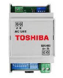
Toshiba BMS-IFMB0AWR-E
Controls Toshiba ESTIA air-to-water heat pump via Modbus RTU interface
Template for the Toshiba BMS-IFMB0AWR-E Modbus RTU interface, used to monitor and control Toshiba ESTIA R410a air-to-water heat pumps. It provides read and write access to zone on/off states, operation modes, temperature setpoints, and hot water settings across 8 registers.
- Protocol
- Modbus RTU
- Connection
- RS485, 9600 baud
- Registers
- 8, read and write
- Brand
- Toshiba
- Key readings
- Zone 1/2 On/Off · Operation Mode · Temperature Setting Zone 1/2 · Hot Water On/Off · Hot Water Temperature Setting · Hot Water Boost On/Off
- Available commands
- Zone 1/2 On/Off · Operation Mode · Temperature Setpoints Zone 1/2 · Hot Water On/Off and Boost
- Compatible models
- BMS-IFMB0AWR-E · ESTIA R410a
- Last updated
Registers (8)
8 read, 8 write
| Name | Unit | Access | Address (Hidden until you enter your email) | Function (hidden) | Type (hidden) |
|---|---|---|---|---|---|
| Zone1/2 On/Off | Read and write | ||||
| Operation Mode | Read and write | ||||
| Temperature setting Zone 1 | Read and write | ||||
| Hot Water On/Off | Read and write | ||||
| Temperature Setting Zone 2 | Read and write | ||||
| Hot water temperature setting | Read and write | ||||
| Auto temp Operation On/Off | Read and write | ||||
| Hot water boost On/Off | Read and write |
Loading registers…
Send your device list
If a device is not in the library yet, we build the template for free as soon as we have the register data.
Use cases
- Monitor Zone 1 and Zone 2 on/off status and temperature setpoints on a live cloud dashboard.
- Adjust hot water temperature setpoints remotely without visiting the installation site.
- Create an alert when the hot water boost activates unexpectedly or remains on for too long.
- Log operation mode changes over time to verify seasonal heating and cooling schedules.
- Remotely switch the heat pump zones on or off during maintenance or fault conditions.
- Compare temperature setpoints across multiple ESTIA installations in a portfolio overview.
Installation
Connect the ModbusCloud Gateway to the BMS-IFMB0AWR-E interface module using a shielded RS-485 cable, wiring A, B, and GND terminals correctly.
Set the Modbus RTU baud rate on the gateway to 9600 to match the BMS-IFMB0AWR-E default communication settings.
Configure the Modbus slave address on the BMS-IFMB0AWR-E module according to its installation manual, and enter the same address in the gateway configuration.
Import the Toshiba BMS-IFMB0AWR-E template from the ModbusCloud template library into your project.
Verify communication by reading Zone 1 on/off status and temperature setpoint from the cloud dashboard.
Test write functionality by changing a temperature setpoint from the dashboard and confirming the new value on the heat pump's local controller.
Things to watch for
What baud rate and serial settings does the BMS-IFMB0AWR-E require?
The interface communicates at 9600 baud over Modbus RTU. Confirm parity and stop bit settings in the module's installation manual, as these must match the gateway configuration exactly.
What register format is used for the data values?
All 8 registers use int16 (signed 16-bit integer) format. No scaling factor or byte order swap is needed beyond the standard Modbus big-endian word order.
Can I read and write all registers, or are some read-only?
All registers in the range 40000 to 40008 are both readable and writable. This means you can monitor status values and also send control commands such as on/off and setpoint changes.
The gateway connects but all values show zero or no response. What should I check?
Verify that the RS-485 wiring polarity (A and B) is correct and that the slave address configured on the gateway matches the address set on the BMS-IFMB0AWR-E module. Also confirm that the interface module is powered and properly connected to the ESTIA heat pump's internal bus.
More Toshiba templates
Want to see how it works?
