








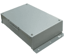
Fujitsu Airstage UTY-VMGX
Controls up to 45 Fujitsu air conditioner units via Modbus converter.
Modbus RTU template for the Fujitsu Airstage UTY-VMGX converter. Reads on/off status and operation mode for up to 45 indoor units, and writes power, operation mode, set temperature, and airflow settings.
- Protocol
- Modbus RTU
- Connection
- RS485, 9600 baud
- Registers
- 227, read and write
- Brand
- Fujitsu
- Key readings
- Unit Status ON/OFF (units 1-45) · Unit Operation Mode (units 1-45)
- Available commands
- Power ON/OFF · Operation Mode · Set Temperature · Airflow
- Compatible models
- UTY-VMGX
- Last updated
Registers (227)
47 read, 180 write
| Name | Unit | Access | Address (Hidden until you enter your email) | Function (hidden) | Type (hidden) |
|---|---|---|---|---|---|
| Unit 01 Status ON OFF | Read | ||||
| Unit 01 Operation mode | Read | ||||
| Unit 16 Status ON OFF | Read | ||||
| Unit 16 Operation mode | Read | ||||
| Unit 02 Status ON OFF | Read | ||||
| Unit 03 Status ON OFF | Read | ||||
| Unit 04 Status ON OFF | Read | ||||
| Unit 05 Status ON OFF | Read | ||||
| Unit 06 Status ON OFF | Read | ||||
| Unit 07 Status ON OFF | Read | ||||
| Unit 08 Status ON OFF | Read | ||||
| Unit 09 Status ON OFF | Read | ||||
| Unit 10 Status ON OFF | Read | ||||
| Unit 11 Status ON OFF | Read | ||||
| Unit 12 Status ON OFF | Read | ||||
| Unit 13 Status ON OFF | Read | ||||
| Unit 14 Status ON OFF | Read | ||||
| Unit 15 Status ON OFF | Read | ||||
| Unit 44 Status ON OFF | Read | ||||
| Unit 45 Status ON OFF | Read | ||||
| Unit 17 Status ON OFF | Read | ||||
| Unit 18 Status ON OFF | Read | ||||
| Unit 19 Status ON OFF | Read | ||||
| Unit 20 Status ON OFF | Read | ||||
| Unit 21 Status ON OFF | Read | ||||
| Unit 22 Status ON OFF | Read | ||||
| Unit 23 Status ON OFF | Read | ||||
| Unit 24 Status ON OFF | Read | ||||
| Unit 25 Status ON OFF | Read | ||||
| Unit 26 Status ON OFF | Read | ||||
| Unit 27 Status ON OFF | Read | ||||
| Unit 28 Status ON OFF | Read | ||||
| Unit 29 Status ON OFF | Read | ||||
| Unit 30 Status ON OFF | Read | ||||
| Unit 31 Status ON OFF | Read | ||||
| Unit 32 Status ON OFF | Read | ||||
| Unit 33 Status ON OFF | Read | ||||
| Unit 34 Status ON OFF | Read | ||||
| Unit 35 Status ON OFF | Read | ||||
| Unit 36 Status ON OFF | Read | ||||
| Unit 37 Status ON OFF | Read | ||||
| Unit 38 Status ON OFF | Read | ||||
| Unit 39 Status ON OFF | Read | ||||
| Unit 40 Status ON OFF | Read | ||||
| Unit 41 Status ON OFF | Read | ||||
| Unit 42 Status ON OFF | Read | ||||
| Unit 43 Status ON OFF | Read | ||||
| Unit 01 Airflow | Write | ||||
| Unit 01 Power ON_OFF | Write | ||||
| Unit 01 Operation Mode | Write | ||||
| Unit 01 Set Temperature | °C | Write | |||
| Unit 16 Airflow | Write | ||||
| Unit 16 Operation Mode | Write | ||||
| Unit 16 Power ON_OFF | Write | ||||
| Unit 16 Set Temperature | °C | Write | |||
| Unit 02 Power ON_OFF | Write | ||||
| Unit 03 Power ON_OFF | Write | ||||
| Unit 04 Power ON_OFF | Write | ||||
| Unit 05 Power ON_OFF | Write | ||||
| Unit 06 Power ON_OFF | Write | ||||
| Unit 07 Power ON_OFF | Write | ||||
| Unit 08 Power ON_OFF | Write | ||||
| Unit 09 Power ON_OFF | Write | ||||
| Unit 10 Power ON_OFF | Write | ||||
| Unit 11 Power ON_OFF | Write | ||||
| Unit 12 Power ON_OFF | Write | ||||
| Unit 13 Power ON_OFF | Write | ||||
| Unit 14 Power ON_OFF | Write | ||||
| Unit 15 Power ON_OFF | Write | ||||
| Unit 44 Power ON_OFF | Write | ||||
| Unit 45 Power ON_OFF | Write | ||||
| Unit 17 Power ON_OFF | Write | ||||
| Unit 18 Power ON_OFF | Write | ||||
| Unit 19 Power ON_OFF | Write | ||||
| Unit 20 Power ON_OFF | Write | ||||
| Unit 21 Power ON_OFF | Write | ||||
| Unit 22 Power ON_OFF | Write | ||||
| Unit 23 Power ON_OFF | Write | ||||
| Unit 24 Power ON_OFF | Write | ||||
| Unit 25 Power ON_OFF | Write | ||||
| Unit 26 Power ON_OFF | Write | ||||
| Unit 27 Power ON_OFF | Write | ||||
| Unit 28 Power ON_OFF | Write | ||||
| Unit 29 Power ON_OFF | Write | ||||
| Unit 30 Power ON_OFF | Write | ||||
| Unit 31 Power ON_OFF | Write | ||||
| Unit 32 Power ON_OFF | Write | ||||
| Unit 33 Power ON_OFF | Write | ||||
| Unit 34 Power ON_OFF | Write | ||||
| Unit 35 Power ON_OFF | Write | ||||
| Unit 36 Power ON_OFF | Write | ||||
| Unit 37 Power ON_OFF | Write | ||||
| Unit 38 Power ON_OFF | Write | ||||
| Unit 39 Power ON_OFF | Write | ||||
| Unit 40 Power ON_OFF | Write | ||||
| Unit 41 Power ON_OFF | Write | ||||
| Unit 42 Power ON_OFF | Write | ||||
| Unit 43 Power ON_OFF | Write | ||||
| Unit 02 Operation Mode | Write | ||||
| Unit 03 Operation Mode | Write | ||||
| Unit 04 Operation Mode | Write | ||||
| Unit 05 Operation Mode | Write | ||||
| Unit 06 Operation Mode | Write | ||||
| Unit 07 Operation Mode | Write | ||||
| Unit 08 Operation Mode | Write | ||||
| Unit 09 Operation Mode | Write | ||||
| Unit 10 Operation Mode | Write | ||||
| Unit 11 Operation Mode | Write | ||||
| Unit 12 Operation Mode | Write | ||||
| Unit 13 Operation Mode | Write | ||||
| Unit 14 Operation Mode | Write | ||||
| Unit 15 Operation Mode | Write | ||||
| Unit 45 Operation Mode | Write | ||||
| Unit 17 Operation Mode | Write | ||||
| Unit 18 Operation Mode | Write | ||||
| Unit 19 Operation Mode | Write | ||||
| Unit 20 Operation Mode | Write | ||||
| Unit 21 Operation Mode | Write | ||||
| Unit 22 Operation Mode | Write | ||||
| Unit 23 Operation Mode | Write | ||||
| Unit 24 Operation Mode | Write | ||||
| Unit 25 Operation Mode | Write | ||||
| Unit 26 Operation Mode | Write | ||||
| Unit 27 Operation Mode | Write | ||||
| Unit 28 Operation Mode | Write | ||||
| Unit 29 Operation Mode | Write | ||||
| Unit 30 Operation Mode | Write | ||||
| Unit 31 Operation Mode | Write | ||||
| Unit 32 Operation Mode | Write | ||||
| Unit 33 Operation Mode | Write | ||||
| Unit 34 Operation Mode | Write | ||||
| Unit 35 Operation Mode | Write | ||||
| Unit 36 Operation Mode | Write | ||||
| Unit 37 Operation Mode | Write | ||||
| Unit 38 Operation Mode | Write | ||||
| Unit 39 Operation Mode | Write | ||||
| Unit 40 Operation Mode | Write | ||||
| Unit 41 Operation Mode | Write | ||||
| Unit 42 Operation Mode | Write | ||||
| Unit 43 Operation Mode | Write | ||||
| Unit 44 Operation Mode | Write | ||||
| Unit 02 Airflow | Write | ||||
| Unit 03 Airflow | Write | ||||
| Unit 04 Airflow | Write | ||||
| Unit 05 Airflow | Write | ||||
| Unit 06 Airflow | Write | ||||
| Unit 07 Airflow | Write | ||||
| Unit 08 Airflow | Write | ||||
| Unit 09 Airflow | Write | ||||
| Unit 10 Airflow | Write | ||||
| Unit 11 Airflow | Write | ||||
| Unit 12 Airflow | Write | ||||
| Unit 13 Airflow | Write | ||||
| Unit 14 Airflow | Write | ||||
| Unit 15 Airflow | Write | ||||
| Unit 45 Airflow | Write | ||||
| Unit 17 Airflow | Write | ||||
| Unit 18 Airflow | Write | ||||
| Unit 19 Airflow | Write | ||||
| Unit 20 Airflow | Write | ||||
| Unit 21 Airflow | Write | ||||
| Unit 22 Airflow | Write | ||||
| Unit 23 Airflow | Write | ||||
| Unit 24 Airflow | Write | ||||
| Unit 25 Airflow | Write | ||||
| Unit 26 Airflow | Write | ||||
| Unit 27 Airflow | Write | ||||
| Unit 28 Airflow | Write | ||||
| Unit 29 Airflow | Write | ||||
| Unit 30 Airflow | Write | ||||
| Unit 31 Airflow | Write | ||||
| Unit 32 Airflow | Write | ||||
| Unit 33 Airflow | Write | ||||
| Unit 34 Airflow | Write | ||||
| Unit 35 Airflow | Write | ||||
| Unit 36 Airflow | Write | ||||
| Unit 37 Airflow | Write | ||||
| Unit 38 Airflow | Write | ||||
| Unit 39 Airflow | Write | ||||
| Unit 40 Airflow | Write | ||||
| Unit 41 Airflow | Write | ||||
| Unit 42 Airflow | Write | ||||
| Unit 43 Airflow | Write | ||||
| Unit 44 Airflow | Write | ||||
| Unit 02 Set Temperature | °C | Write | |||
| Unit 03 Set Temperature | °C | Write | |||
| Unit 04 Set Temperature | °C | Write | |||
| Unit 05 Set Temperature | °C | Write | |||
| Unit 06 Set Temperature | °C | Write | |||
| Unit 07 Set Temperature | °C | Write | |||
| Unit 08 Set Temperature | °C | Write | |||
| Unit 09 Set Temperature | °C | Write | |||
| Unit 10 Set Temperature | °C | Write | |||
| Unit 11 Set Temperature | °C | Write | |||
| Unit 12 Set Temperature | °C | Write | |||
| Unit 13 Set Temperature | °C | Write | |||
| Unit 14 Set Temperature | °C | Write | |||
| Unit 15 Set Temperature | °C | Write | |||
| Unit 45 Set Temperature | °C | Write | |||
| Unit 17 Set Temperature | °C | Write | |||
| Unit 18 Set Temperature | °C | Write | |||
| Unit 19 Set Temperature | °C | Write | |||
| Unit 20 Set Temperature | °C | Write | |||
| Unit 21 Set Temperature | °C | Write | |||
| Unit 22 Set Temperature | °C | Write | |||
| Unit 23 Set Temperature | °C | Write | |||
| Unit 24 Set Temperature | °C | Write | |||
| Unit 25 Set Temperature | °C | Write | |||
| Unit 26 Set Temperature | °C | Write | |||
| Unit 27 Set Temperature | °C | Write | |||
| Unit 28 Set Temperature | °C | Write | |||
| Unit 29 Set Temperature | °C | Write | |||
| Unit 30 Set Temperature | °C | Write | |||
| Unit 31 Set Temperature | °C | Write | |||
| Unit 32 Set Temperature | °C | Write | |||
| Unit 33 Set Temperature | °C | Write | |||
| Unit 34 Set Temperature | °C | Write | |||
| Unit 35 Set Temperature | °C | Write | |||
| Unit 36 Set Temperature | °C | Write | |||
| Unit 37 Set Temperature | °C | Write | |||
| Unit 38 Set Temperature | °C | Write | |||
| Unit 39 Set Temperature | °C | Write | |||
| Unit 40 Set Temperature | °C | Write | |||
| Unit 41 Set Temperature | °C | Write | |||
| Unit 42 Set Temperature | °C | Write | |||
| Unit 43 Set Temperature | °C | Write | |||
| Unit 44 Set Temperature | °C | Write |
Loading registers…
Send your device list
If a device is not in the library yet, we build the template for free as soon as we have the register data.
Use cases
- Monitor on/off status and operation mode of all connected Fujitsu indoor units on a single dashboard.
- Adjust setpoint temperatures remotely for individual air conditioning units without on-site visits.
- Create alerts when a unit switches off unexpectedly or changes to an unintended operation mode.
- Log airflow and temperature setpoint changes over time to verify compliance with energy management policies.
- Control power state for groups of indoor units based on occupancy schedules or time-of-day rules.
Installation
Connect the Fujitsu UTY-VMGX converter to the Fujitsu indoor units via the proprietary communication bus, following the wiring instructions in the UTY-VMGX manual.
Wire the RS-485 Modbus RTU connection from the UTY-VMGX to the ModbusCloud Gateway, observing correct A, B, and GND terminal assignments.
Set the Modbus slave address on the UTY-VMGX converter to match the address configured in the ModbusCloud template.
Configure the serial port on the ModbusCloud gateway to 9600 baud, odd parity, and 1 stop bit to match the UTY-VMGX defaults.
Import the Fujitsu Airstage UTY-VMGX template in the ModbusCloud platform and assign it to the correct gateway and slave address.
Verify that read registers return valid on/off status and operation mode data for each connected indoor unit before deploying write commands.
Things to watch for
Why am I not getting any data from the UTY-VMGX converter?
Check that the RS-485 wiring is correct, with A, B, and GND properly connected. Confirm that the gateway serial port is set to 9600 baud with odd parity. Also verify that the Modbus slave address on the converter matches the address configured in ModbusCloud.
How do I address a specific indoor unit in the register map?
Each indoor unit uses a block of 60 registers. Write registers for unit 1 start at address 1, and read registers for unit 1 start at address 53. For unit N, offset both starting addresses by (N minus 1) times 60.
Can I control fewer than 45 units with this template?
Yes. The template supports up to 45 units, but you only need to poll the registers corresponding to the units that are physically connected. Unused unit registers can be disabled in the ModbusCloud configuration to reduce unnecessary polling.
What parity setting does the UTY-VMGX require?
The UTY-VMGX uses odd parity at 9600 baud. If parity is set incorrectly on your Modbus gateway, communication will fail or return CRC errors.
More Fujitsu templates
Want to see how it works?
