








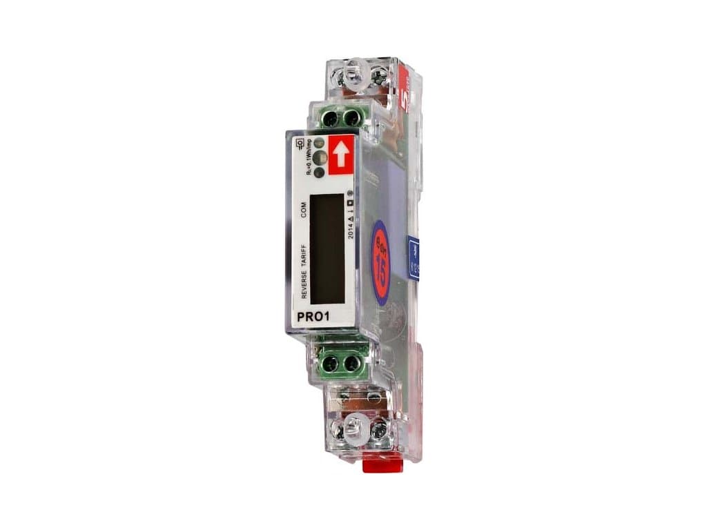
INEPRO PRO1-Mod
Monitors single-phase energy metering via Modbus RTU.
The INEPRO PRO1-Mod is a single-phase energy meter with Modbus RTU connectivity. This template reads voltage, current, active/reactive/apparent power, energy totals, frequency, and power factor. All registers use float32 format with addresses specified in HEX.
- Protocol
- Modbus RTU
- Connection
- RS485, 9600 baud
- Registers
- 9, read only
- Brand
- Inepro
- Key readings
- Voltage · Current · Grid Frequency · Total Active Power · Total Reactive Power · Total Apparent Power
- Compatible models
- INEPRO PRO1-Mod
- Last updated
Registers (9)
9 read, 0 write
| Name | Unit | Access | Address (Hidden until you enter your email) | Function (hidden) | Type (hidden) |
|---|---|---|---|---|---|
| Voltage | V | Read | |||
| Grid Frequency | Hz | Read | |||
| Current | A | Read | |||
| Total Active Power | W | Read | |||
| Total Reactive Power | var | Read | |||
| Total Apparent Power | VA | Read | |||
| Power Factor | Read | ||||
| Total Active Energy | Wh | Read | |||
| Total Reactive Energy | varh | Read |
Loading registers…
Send your device list
If a device is not in the library yet, we build the template for free as soon as we have the register data.
Use cases
- Monitor real-time voltage, current, and power consumption of a single-phase circuit on a live dashboard.
- Track cumulative energy usage per tenant or per load for accurate billing and cost allocation.
- Create an alert when power factor drops below a defined threshold to detect potential power quality issues.
- Log forward and reverse energy totals to verify solar self-consumption on a single-phase inverter circuit.
- Generate weekly or monthly energy consumption reports and share them with your customer via a dashboard link.
- Compare grid frequency trends over time to identify supply stability issues in remote locations.
Installation
Wire the INEPRO PRO1-Mod into the single-phase circuit according to the manufacturer's installation guide, ensuring correct line and neutral connections.
Connect the RS485 A and B terminals of the meter to the corresponding terminals on your ModbusCloud Gateway, and add a 120 ohm termination resistor if this is the last device on the bus.
Set the Modbus slave address on the meter using its front-panel buttons or DIP switches, and note the address for gateway configuration.
Confirm the meter is configured for 9600 baud and odd parity (the factory defaults), matching the template settings.
Import the INEPRO PRO1-Mod template in the ModbusCloud platform and assign it to the correct gateway and slave address.
Verify that live readings such as voltage and current appear on the ModbusCloud dashboard before closing the installation.
Things to watch for
I see zero or null values for all registers. What should I check?
Verify that the baud rate is set to 9600 and parity is set to odd (1 stop bit) on both the meter and the gateway. A mismatch in either setting will prevent successful communication.
The register addresses in the documentation are in HEX. Do I need to convert them?
The ModbusCloud template already maps the correct decimal register addresses. If you add custom registers manually, convert the HEX addresses from the documentation to decimal before entering them.
My readings look extremely large or appear as random numbers. What is wrong?
All registers on the PRO1-Mod are float32 values spanning two consecutive registers. Make sure your gateway is configured to read 32-bit floats with the correct byte order (big-endian). An incorrect byte or word swap will produce garbled values.
Can I connect multiple INEPRO PRO1-Mod meters on the same RS485 bus?
Yes. Assign a unique Modbus slave address to each meter and create a separate template instance in ModbusCloud for each address. Keep the total cable length under 1200 meters and use proper daisy-chain wiring.
More Inepro templates
Want to see how it works?
