
Mitsubishi Electric FR-A800
Frequency inverter that controls motor speed and torque in pumps, fans, conveyors and machines.
The Mitsubishi Electric FR-A800 is a frequency inverter that controls the speed and torque of motors in pumps, fans, conveyors and machines. This Modbus RTU template reads frequency, current, voltage, power, energy, temperatures and the fault history, and lets you write run commands, the frequency setpoint and every drive parameter from ModbusCloud.
- Protocol
- Modbus RTU
- Connection
- RS485, 9600 baud
- Registers
- 1067, read and write
- Brand
- Mitsubishi Electric
- Key readings
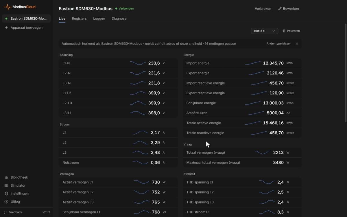
- Output frequency · Output current · Output voltage · Input power · Cumulative energy · Heat sink temperature · Motor thermal load · Fault history
- Available commands
- Run and direction command · Frequency setpoint · Operation mode · PID set point · Acceleration and deceleration time · Inverter reset
- Compatible models
- FR-A820 · FR-A840 · FR-A842 · FR-A846 · FR-A800-GF
- Last updated
Registers (1067)
1061 read, 956 write
| Name | Unit | Access | Address (Hidden until you enter your email) | Function (hidden) | Type (hidden) |
|---|---|---|---|---|---|
| Output Frequency | Hz | Read | 200 | FC03 | uint16 |
| Output Current | A | Read | 201 | FC03 | uint16 |
| Output Voltage | V | Read | 202 | FC03 | uint16 |
| Control Input Command / Inverter Status | Read and write | 8 | FC03 / FC06 | uint16 | |
| Operation Mode | Read and write | 9 | FC03 / FC06 | uint16 | |
| Set Frequency RAM | Hz | Read and write | |||
| Set Frequency EEPROM | Hz | Write | |||
| Set Frequency | Hz | Read | |||
| Operation Speed | rpm | Read | |||
| Motor Torque | % | Read | |||
| Converter Output Voltage | V | Read | |||
| Regenerative Brake Duty | % | Read | |||
| Electronic Thermal O/L Relay Load Factor | % | Read | |||
| Output Current Peak Value | A | Read | |||
| Converter Output Voltage Peak Value | V | Read | |||
| Input Power | kW | Read | |||
| Output Power | kW | Read | |||
| Load Meter | % | Read | |||
| Motor Excitation Current | A | Read | |||
| Position Pulse | Read | ||||
| Cumulative Energization Time | h | Read | |||
| Orientation Status | Read | ||||
| Actual Operation Time | h | Read | |||
| Motor Load Factor | % | Read | |||
| Cumulative Energy | kWh | Read | |||
| Position Command Lower Digits | Read | ||||
| Position Command Upper Digits | Read | ||||
| Current Position Lower Digits | Read | ||||
| Current Position Upper Digits | Read | ||||
| Droop Pulse Lower Digits | Read | ||||
| Droop Pulse Upper Digits | Read | ||||
| Torque Command | % | Read | |||
| Torque Current Command | % | Read | |||
| Motor Output | kW | Read | |||
| Feedback Pulse | Read | ||||
| Torque | % | Read | |||
| Heat Sink Temperature | °C | Read | |||
| Trace Status | Read | ||||
| SSCNET III Communication Status | Read | ||||
| PLC Function User Monitor 1 | Read | ||||
| PLC Function User Monitor 2 | Read | ||||
| PLC Function User Monitor 3 | Read | ||||
| Station Number RS-485 Terminals | Read | ||||
| Station Number PU | Read | ||||
| Station Number CC-Link | Read | ||||
| Motor Temperature | °C | Read | |||
| Energy Saving Effect | Read | ||||
| Cumulative Saved Energy | Read | ||||
| PID Set Point | % | Read | |||
| PID Measured Value | % | Read | |||
| PID Deviation | % | Read | |||
| Option Input Terminal Status 1 | Read | ||||
| Option Input Terminal Status 2 | Read | ||||
| Option Output Terminal Status | Read | ||||
| Motor Thermal Load Factor | % | Read | |||
| Inverter Thermal Load Factor | % | Read | |||
| PTC Thermistor Resistance | kΩ | Read | |||
| PID Measured Value 2 | % | Read | |||
| Emergency Drive Status | Read | ||||
| Cumulative Pulse | Read | ||||
| Cumulative Pulse Overflow Times | Read | ||||
| Cumulative Pulse Control Terminal Option | Read | ||||
| Cumulative Pulse Overflow Times Control Terminal Option | Read | ||||
| Multi-Revolution Counter | Read | ||||
| Remote Output Value 1 | % | Read | |||
| Remote Output Value 2 | % | Read | |||
| Remote Output Value 3 | % | Read | |||
| Remote Output Value 4 | % | Read | |||
| PID Manipulated Amount | % | Read | |||
| Second PID Set Point | % | Read | |||
| Second PID Measured Value | % | Read | |||
| Second PID Deviation | % | Read | |||
| Second PID Measured Value 2 | % | Read | |||
| Second PID Manipulated Amount | % | Read | |||
| Dancer Main Set Speed | Hz | Read | |||
| Control Circuit Temperature | °C | Read | |||
| Input Terminal Status | Read | ||||
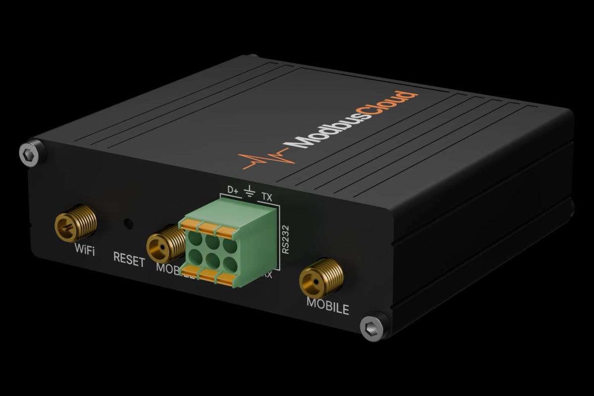
| Output Terminal Status | Read | ||||
| 32-Bit Cumulative Energy kWh | kWh | Read | |||
| 32-Bit Cumulative Energy | kWh | Read | |||
| Fault Record 1 | Read and write | ||||
| Fault Record 2 | Read | ||||
| Fault Record 3 | Read | ||||
| Fault Record 4 | Read | ||||
| Fault Record 5 | Read | ||||
| Fault Record 6 | Read | ||||
| Fault Record 7 | Read | ||||
| Fault Record 8 | Read | ||||
| Inverter Reset | Write | ||||
| Parameter Clear | Write | ||||
| All Parameter Clear | Write | ||||
| Parameter Clear Except Communication | Write | ||||
| All Parameter Clear Except Communication | Write | ||||
| Torque Boost | % | Read and write | |||
| Maximum Frequency | Hz | Read and write | |||
| Minimum Frequency | Hz | Read and write | |||
| Base Frequency | Hz | Read and write | |||
| Multi-Speed Setting (High Speed) | Hz | Read and write | |||
| Multi-Speed Setting (Middle Speed) | Hz | Read and write | |||
| Multi-Speed Setting (Low Speed) | Hz | Read and write | |||
| Acceleration Time | s | Read and write | |||
| Deceleration Time | s | Read and write | |||
| Electronic Thermal O/L Relay (Rated Motor Current) | A | Read and write | |||
| DC Injection Brake Operation Frequency | Hz | Read and write | |||
| DC Injection Brake Operation Time | s | Read and write | |||
| DC Injection Brake Operation Voltage | % | Read and write | |||
| Starting Frequency | Hz | Read and write | |||
| Load Pattern Selection | Read and write | ||||
| Jog Frequency | Hz | Read and write | |||
| Jog Acceleration/Deceleration Time | s | Read and write | |||
| MRS Input Selection | Read and write | ||||
| High Speed Maximum Frequency | Hz | Read and write | |||
| Base Frequency Voltage | V | Read and write | |||
| Acceleration/Deceleration Reference Frequency | Hz | Read and write | |||
| Acceleration/Deceleration Time Increments | Read and write | ||||
| Stall Prevention Operation Level (Torque Limit Level) | % | Read and write | |||
| Stall Prevention Level Compensation Factor at Double Speed | % | Read and write | |||
| Multi-Speed Setting (Speed 4) | Hz | Read and write | |||
| Multi-Speed Setting (Speed 5) | Hz | Read and write | |||
| Multi-Speed Setting (Speed 6) | Hz | Read and write | |||
| Multi-Speed Setting (Speed 7) | Hz | Read and write | |||
| Multi-Speed Input Compensation Selection | Read and write | ||||
| Acceleration/Deceleration Pattern Selection | Read and write | ||||
| Regenerative Function Selection | Read and write | ||||
| Frequency Jump 1A | Hz | Read and write | |||
| Frequency Jump 1B | Hz | Read and write | |||
| Frequency Jump 2A | Hz | Read and write | |||
| Frequency Jump 2B | Hz | Read and write | |||
| Frequency Jump 3A | Hz | Read and write | |||
| Frequency Jump 3B | Hz | Read and write | |||
| Speed Display | Read and write | ||||
| Up-To-Frequency Sensitivity | % | Read and write | |||
| Output Frequency Detection | Hz | Read and write | |||
| Output Frequency Detection for Reverse Rotation | Hz | Read and write | |||
| Second Acceleration/Deceleration Time | s | Read and write | |||
| Second Deceleration Time | s | Read and write | |||
| Second Torque Boost | % | Read and write | |||
| Second V/F (Base Frequency) | Hz | Read and write | |||
| Second Stall Prevention Operation Level | % | Read and write | |||
| Second Stall Prevention Operation Frequency | Hz | Read and write | |||
| Second Output Frequency Detection | Hz | Read and write | |||
| Second Electronic Thermal O/L Relay | A | Read and write | |||
| Operation Panel Main Monitor Selection | Read and write | ||||
| FM/CA Terminal Function Selection | Read and write | ||||
| Frequency Monitoring Reference | Hz | Read and write | |||
| Current Monitoring Reference | A | Read and write | |||
| Restart Coasting Time | s | Read and write | |||
| Restart Cushion Time | s | Read and write | |||
| Remote Function Selection | Read and write | ||||
| Energy Saving Control Selection | Read and write | ||||
| Reference Current | A | Read and write | |||
| Reference Value at Acceleration | % | Read and write | |||
| Reference Value at Deceleration | % | Read and write | |||
| Starting Frequency for Elevator Mode | Hz | Read and write | |||
| Retry Selection | Read and write | ||||
| Stall Prevention Operation Reduction Starting Frequency | Hz | Read and write | |||
| Number of Retries at Fault Occurrence | Read and write | ||||
| Retry Waiting Time | s | Read and write | |||
| Retry Count Display Erase | Read and write | ||||
| Special Regenerative Brake Duty | % | Read and write | |||
| Applied Motor | Read and write | ||||
| PWM Frequency Selection | Read and write | ||||
| Analog Input Selection | Read and write | ||||
| Input Filter Time Constant | Read and write | ||||
| Reset Selection / Disconnected PU Detection / PU Stop | Read and write | ||||
| Fault Code Output Selection | Read and write | ||||
| Parameter Write Selection | Read and write | ||||
| Reverse Rotation Prevention Selection | Read and write | ||||
| Operation Mode Selection | Read and write | ||||
| Motor Capacity | kW | Read and write | |||
| Number of Motor Poles | Read and write | ||||
| Motor Excitation Current (Pr.82) | A | Read and write | |||
| Rated Motor Voltage | V | Read and write | |||
| Rated Motor Frequency | Hz | Read and write | |||
| Excitation Current Break Point | Hz | Read and write | |||
| Excitation Current Low-Speed Scaling Factor | % | Read and write | |||
| Speed Control Gain (Advanced Magnetic Flux Vector) | % | Read and write | |||
| Motor Constant (R1) | Ω | Read and write | |||
| Motor Constant (R2) | Ω | Read and write | |||
| Motor Constant (L1)/D-Axis Inductance (Ld) | Read and write | ||||
| Motor Constant (L2)/Q-Axis Inductance (Lq) | Read and write | ||||
| Motor Constant (X) | % | Read and write | |||
| Online Auto Tuning Selection | Read and write | ||||
| Auto Tuning Setting/Status | Read and write | ||||
| V/F1 (First Frequency) | Hz | Read and write | |||
| V/F1 (First Frequency Voltage) | V | Read and write | |||
| V/F2 (Second Frequency) | Hz | Read and write | |||
| V/F2 (Second Frequency Voltage) | V | Read and write | |||
| V/F3 (Third Frequency) | Hz | Read and write | |||
| V/F3 (Third Frequency Voltage) | V | Read and write | |||
| V/F4 (Fourth Frequency) | Hz | Read and write | |||
| V/F4 (Fourth Frequency Voltage) | V | Read and write | |||
| V/F5 (Fifth Frequency) | Hz | Read and write | |||
| V/F5 (Fifth Frequency Voltage) | V | Read and write | |||
| Third Acceleration/Deceleration Time | s | Read and write | |||
| Third Deceleration Time | s | Read and write | |||
| Third Torque Boost | % | Read and write | |||
| Third V/F (Base Frequency) | Hz | Read and write | |||
| Third Stall Prevention Operation Level | % | Read and write | |||
| Third Stall Prevention Operation Frequency | Hz | Read and write | |||
| Third Output Frequency Detection | Hz | Read and write | |||
| PU Communication Station Number | Read and write | ||||
| PU Communication Speed | Read and write | ||||
| PU Communication Stop Bit Length / Data Length | Read and write | ||||
| PU Communication Parity Check | Read and write | ||||
| PU Communication Retry Count | Read and write | ||||
| PU Communication Check Time Interval | s | Read and write | |||
| PU Communication Waiting Time Setting | ms | Read and write | |||
| PU Communication CR/LF Selection | Read and write | ||||
| Terminal 2 Frequency Setting Gain Frequency | Hz | Read and write | |||
| Terminal 4 Frequency Setting Gain Frequency | Hz | Read and write | |||
| PID Control Automatic Switchover Frequency | Hz | Read and write | |||
| PID Action Selection | Read and write | ||||
| PID Proportional Band | % | Read and write | |||
| PID Integral Time | s | Read and write | |||
| PID Upper Limit | % | Read and write | |||
| PID Lower Limit | % | Read and write | |||
| PID Action Set Point | % | Read and write | |||
| PID Differential Time | s | Read and write | |||
| Electronic Bypass Sequence Selection | Read and write | ||||
| MC Switchover Interlock Time | s | Read and write | |||
| Start Waiting Time | s | Read and write | |||
| Bypass Selection at a Fault | Read and write | ||||
| Automatic Switchover Frequency Inverter to Bypass | Hz | Read and write | |||
| Backlash Acceleration Stopping Frequency | Hz | Read and write | |||
| Backlash Acceleration Stopping Time | s | Read and write | |||
| Backlash Deceleration Stopping Frequency | Hz | Read and write | |||
| Backlash Deceleration Stopping Time | s | Read and write | |||
| Speed Setting Switchover | Read and write | ||||
| PU Display Language Selection | Read and write | ||||
| Acceleration/Deceleration Time Switching Frequency | Hz | Read and write | |||
| Stall Prevention Level at 0 V Input | % | Read and write | |||
| Stall Prevention Level at 10 V Input | % | Read and write | |||
| Output Current Detection Level | % | Read and write | |||
| Output Current Detection Signal Delay Time | s | Read and write | |||
| Zero Current Detection Level | % | Read and write | |||
| Zero Current Detection Time | s | Read and write | |||
| Voltage Reduction Selection during Stall Prevention Operation | Read and write | ||||
| RT Signal Function Validity Condition Selection | Read and write | ||||
| Stall Prevention Operation Selection | Read and write | ||||
| OL Signal Output Timer | s | Read and write | |||
| AM Terminal Function Selection | Read and write | ||||
| Automatic Switchover Frequency Range Bypass to Inverter | Hz | Read and write | |||
| User Group Read Selection | Read and write | ||||
| Frequency Setting/Key Lock Operation Selection | Read and write | ||||
| Automatic Restart after Instantaneous Power Failure Selection | Read and write | ||||
| First Cushion Time for Restart | s | Read and write | |||
| First Cushion Voltage for Restart | % | Read and write | |||
| Stall Prevention Operation Level for Restart | % | Read and write | |||
| Output Current Detection Signal Retention Time | s | Read and write | |||
| Output Current Detection Operation Selection | Read and write | ||||
| Watt-Hour Meter Clear | Read and write | ||||
| Operation Hour Meter Clear | Read and write | ||||
| User Group Registered Display/Batch Clear | Read and write | ||||
| User Group Registration | Read and write | ||||
| User Group Clear | Read and write | ||||
| STF Terminal Function Selection | Read and write | ||||
| STR Terminal Function Selection | Read and write | ||||
| RL Terminal Function Selection | Read and write | ||||
| RM Terminal Function Selection | Read and write | ||||
| RH Terminal Function Selection | Read and write | ||||
| RT Terminal Function Selection | Read and write | ||||
| AU Terminal Function Selection | Read and write | ||||
| JOG Terminal Function Selection | Read and write | ||||
| CS Terminal Function Selection | Read and write | ||||
| MRS Terminal Function Selection | Read and write | ||||
| STOP Terminal Function Selection | Read and write | ||||
| RES Terminal Function Selection | Read and write | ||||
| RUN Terminal Function Selection | Read and write | ||||
| SU Terminal Function Selection | Read and write | ||||
| IPF Terminal Function Selection | Read and write | ||||
| OL Terminal Function Selection | Read and write | ||||
| FU Terminal Function Selection | Read and write | ||||
| ABC1 Terminal Function Selection | Read and write | ||||
| ABC2 Terminal Function Selection | Read and write | ||||
| Excitation Current Compensation Point 1 | % | Read and write | |||
| Inductance Compensation Rate 1 | % | Read and write | |||
| Excitation Current Compensation Point 2 | % | Read and write | |||
| Inductance Compensation Rate 2 | % | Read and write | |||
| Excitation Current Compensation Point 3 | % | Read and write | |||
| Inductance Compensation Rate 3 | % | Read and write | |||
| Excitation Current Compensation Point 4 | % | Read and write | |||
| Inductance Compensation Rate 4 | % | Read and write | |||
| Multi-Speed Setting (Speed 8) | Hz | Read and write | |||
| Multi-Speed Setting (Speed 9) | Hz | Read and write | |||
| Multi-Speed Setting (Speed 10) | Hz | Read and write | |||
| Multi-Speed Setting (Speed 11) | Hz | Read and write | |||
| Multi-Speed Setting (Speed 12) | Hz | Read and write | |||
| Multi-Speed Setting (Speed 13) | Hz | Read and write | |||
| Multi-Speed Setting (Speed 14) | Hz | Read and write | |||
| Multi-Speed Setting (Speed 15) | Hz | Read and write | |||
| Soft-PWM Operation Selection | Read and write | ||||
| Analog Input Display Unit Switchover | Read and write | ||||
| Terminal 1 Added Compensation Amount (Terminal 2) | % | Read and write | |||
| Terminal 1 Added Compensation Amount (Terminal 4) | % | Read and write | |||
| Cooling Fan Operation Selection | Read and write | ||||
| Rated Slip | % | Read and write | |||
| Slip Compensation Time Constant | s | Read and write | |||
| Constant Output Range Slip Compensation Selection | Read and write | ||||
| Self Power Management Selection | Read and write | ||||
| Earth (Ground) Fault Detection at Start | Read and write | ||||
| Stop Selection | s | Read and write | |||
| Output Phase Loss Protection Selection | Read and write | ||||
| Override Bias | % | Read and write | |||
| Override Gain | % | Read and write | |||
| Main Circuit Power OFF Waiting Time | s | Read and write | |||
| Life Alarm Status Display | Read | ||||
| Inrush Current Limit Circuit Life Display | % | Read | |||
| Control Circuit Capacitor Life Display | % | Read | |||
| Main Circuit Capacitor Life Display | % | Read | |||
| Main Circuit Capacitor Life Measuring | Read and write | ||||
| PWM Frequency Automatic Switchover | Read and write | ||||
| Power Failure Stop Selection | Read and write | ||||
| Subtracted Frequency at Deceleration Start | Hz | Read and write | |||
| Subtraction Starting Frequency | Hz | Read and write | |||
| Power-Failure Deceleration Time 1 | s | Read and write | |||
| Power-Failure Deceleration Time 2 | s | Read and write | |||
| Power Failure Deceleration Time Switchover Frequency | Hz | Read and write | |||
| Terminal 4 Input Selection | Read and write | ||||
| Monitor Decimal Digits Selection | Read and write | ||||
| Stop-On Contact/Load Torque High-Speed Control Selection | Read and write | ||||
| High-Speed Setting Maximum Current | % | Read and write | |||
| Middle-Speed Setting Minimum Current | % | Read and write | |||
| Current Averaging Range | Hz | Read and write | |||
| Current Averaging Filter Time Constant | Read and write | ||||
| Stop-On Contact Excitation Current Low-Speed Scaling Factor | % | Read and write | |||
| PWM Carrier Frequency at Stop-On Contact | Read and write | ||||
| Brake Opening Frequency | Hz | Read and write | |||
| Brake Opening Current | % | Read and write | |||
| Brake Opening Current Detection Time | s | Read and write | |||
| Brake Operation Time at Start | s | Read and write | |||
| Brake Operation Frequency | Hz | Read and write | |||
| Brake Operation Time at Stop | s | Read and write | |||
| Deceleration Detection Function Selection | Read and write | ||||
| Overspeed Detection Frequency | Hz | Read and write | |||
| Droop Gain | % | Read and write | |||
| Droop Filter Time Constant | s | Read and write | |||
| Droop Function Activation Selection | Read and write | ||||
| Inverter Output Terminal Filter | ms | Read and write | |||
| Monitor Negative Output Selection | Read and write | ||||
| Pulse Train I/O Selection | Read and write | ||||
| Automatic Acceleration/Deceleration | Read and write | ||||
| Acceleration/Deceleration Separate Selection | Read and write | ||||
| UV Avoidance Voltage Gain | % | Read and write | |||
| Frequency Change Increment Amount Setting | Read and write | ||||
| Password Lock Level | Read and write | ||||
| Password Lock/Unlock | Read and write | ||||
| Frequency Search Gain | Read and write | ||||
| Rotation Direction Detection Selection at Restarting | Read and write | ||||
| DO0 Output Selection | Read and write | ||||
| DO1 Output Selection | Read and write | ||||
| DO2 Output Selection | Read and write | ||||
| DO3 Output Selection | Read and write | ||||
| DO4 Output Selection | Read and write | ||||
| DO5 Output Selection | Read and write | ||||
| DO6 Output Selection | Read and write | ||||
| RA1 Output Selection | Read and write | ||||
| RA2 Output Selection | Read and write | ||||
| RA3 Output Selection | Read and write | ||||
| Inverter/Converter Switching | Read and write | ||||
| RS-485 Communication Station Number | Read and write | ||||
| RS-485 Communication Speed | Read and write | ||||
| RS-485 Communication Stop Bit Length / Data Length | Read and write | ||||
| RS-485 Communication Parity Check Selection | Read and write | ||||
| RS-485 Communication Retry Count | Read and write | ||||
| RS-485 Communication Check Time Interval | s | Read and write | |||
| RS-485 Communication Waiting Time Setting | ms | Read and write | |||
| Communication Operation Command Source | Read and write | ||||
| Communication Speed Command Source | Read and write | ||||
| Communication Startup Mode Selection | Read and write | ||||
| RS-485 Communication CR/LF Selection | Read and write | ||||
| Communication EEPROM Write Selection | Read and write | ||||
| Communication Error Count | Read | ||||
| Communication Reset Selection | Read and write | ||||
| Stop Position Command Selection | Read and write | ||||
| Orientation Speed | Hz | Read and write | |||
| Creep Speed | Hz | Read and write | |||
| Creep Switchover Position | Read and write | ||||
| Position Loop Switchover Position | Read and write | ||||
| DC Injection Brake Start Position | Read and write | ||||
| Internal Stop Position Command | Read and write | ||||
| Orientation In-Position Zone | Read and write | ||||
| Servo Torque Selection | Read and write | ||||
| Encoder Rotation Direction | Read and write | ||||
| 16-Bit Data Selection | Read and write | ||||
| Position Shift | Read and write | ||||
| Orientation Position Loop Gain | Read and write | ||||
| Completion Signal Output Delay Time | s | Read and write | |||
| Encoder Stop Check Time | s | Read and write | |||
| Orientation Limit | s | Read and write | |||
| Recheck Time | s | Read and write | |||
| Speed Feedback Range | Hz | Read and write | |||
| Feedback Gain | Read and write | ||||
| Number of Encoder Pulses | Read and write | ||||
| Encoder Position Tuning Setting/Status | Read and write | ||||
| Overspeed Detection Level | Hz | Read and write | |||
| Encoder Signal Loss Detection Enable/Disable Selection | Read and write | ||||
| Acceleration S-Pattern 1 | % | Read and write | |||
| Deceleration S-Pattern 1 | % | Read and write | |||
| Acceleration S-Pattern 2 | % | Read and write | |||
| Deceleration S-Pattern 2 | % | Read and write | |||
| Input Pulse Division Scaling Factor | Read and write | ||||
| Frequency for Zero Input Pulse | Hz | Read and write | |||
| Frequency for Maximum Input Pulse | Hz | Read and write | |||
| Orientation Selection | Read and write | ||||
| Number of Machine Side Gear Teeth | Read and write | ||||
| Number of Motor Side Gear Teeth | Read and write | ||||
| Orientation Speed Gain (P Term) | Read and write | ||||
| Orientation Speed Integral Time | s | Read and write | |||
| Orientation Speed Gain (D Term) | Read and write | ||||
| Orientation Deceleration Ratio | Read and write | ||||
| Encoder Pulse Division Ratio | Read and write | ||||
| PLC Function Operation Selection | Read and write | ||||
| Inverter Operation Lock Mode Setting | Read and write | ||||
| Pre-Scale Function Selection | Read and write | ||||
| Pre-Scale Setting Value | Read and write | ||||
| Position Command Source Selection | Read and write | ||||
| Command Pulse Scaling Factor Numerator | Read and write | ||||
| Command Pulse Multiplication Denominator | Read and write | ||||
| Position Control Gain | Read and write | ||||
| Position Feed Forward Gain | % | Read and write | |||
| Position Command Acceleration/Deceleration Time Constant | s | Read and write | |||
| Position Feed Forward Command Filter | s | Read and write | |||
| In-Position Width | Read and write | ||||
| Excessive Level Error | Read and write | ||||
| Command Pulse Selection | Read and write | ||||
| Clear Signal Selection | Read and write | ||||
| Pulse Monitor Selection | Read and write | ||||
| Pulse Train Torque Command Bias | % | Read and write | |||
| Pulse Train Torque Command Gain | % | Read and write | |||
| Network Number (CC-Link IE) | Read and write | ||||
| Station Number (CC-Link IE) | Read and write | ||||
| Model Position Control Gain | Read and write | ||||
| Second Applied Motor | Read and write | ||||
| Second Motor Control Method Selection | Read and write | ||||
| Second Motor Capacity | kW | Read and write | |||
| Number of Second Motor Poles | Read and write | ||||
| Second Motor Excitation Current | A | Read and write | |||
| Rated Second Motor Voltage | V | Read and write | |||
| Rated Second Motor Frequency | Hz | Read and write | |||
| Second Motor Constant (R1) | Ω | Read and write | |||
| Second Motor Constant (R2) | Ω | Read and write | |||
| Second Motor Constant (L1)/D-Axis Inductance (Ld) | Read and write | ||||
| Second Motor Constant (L2)/Q-Axis Inductance (Lq) | Read and write | ||||
| Second Motor Constant (X) | % | Read and write | |||
| Second Motor Auto Tuning Setting/Status | Read and write | ||||
| Digital Position Control Sudden Stop Deceleration Time | s | Read and write | |||
| First Target Position Lower 4 Digits | Read and write | ||||
| First Target Position Upper 4 Digits | Read and write | ||||
| Second Target Position Lower 4 Digits | Read and write | ||||
| Second Target Position Upper 4 Digits | Read and write | ||||
| Third Target Position Lower 4 Digits | Read and write | ||||
| Third Target Position Upper 4 Digits | Read and write | ||||
| Fourth Target Position Lower 4 Digits | Read and write | ||||
| Fourth Target Position Upper 4 Digits | Read and write | ||||
| Fifth Target Position Lower 4 Digits | Read and write | ||||
| Fifth Target Position Upper 4 Digits | Read and write | ||||
| Sixth Target Position Lower 4 Digits | Read and write | ||||
| Sixth Target Position Upper 4 Digits | Read and write | ||||
| Seventh Target Position Lower 4 Digits | Read and write | ||||
| Seventh Target Position Upper 4 Digits | Read and write | ||||
| Eighth Target Position Lower 4 Digits | Read and write | ||||
| Eighth Target Position Upper 4 Digits | Read and write | ||||
| Ninth Target Position Lower 4 Digits | Read and write | ||||
| Ninth Target Position Upper 4 Digits | Read and write | ||||
| Tenth Target Position Lower 4 Digits | Read and write | ||||
| Tenth Target Position Upper 4 Digits | Read and write | ||||
| Eleventh Target Position Lower 4 Digits | Read and write | ||||
| Eleventh Target Position Upper 4 Digits | Read and write | ||||
| Twelfth Target Position Lower 4 Digits | Read and write | ||||
| Twelfth Target Position Upper 4 Digits | Read and write | ||||
| Thirteenth Target Position Lower 4 Digits | Read and write | ||||
| Thirteenth Target Position Upper 4 Digits | Read and write | ||||
| Fourteenth Target Position Lower 4 Digits | Read and write | ||||
| Fourteenth Target Position Upper 4 Digits | Read and write | ||||
| Fifteenth Target Position Lower 4 Digits | Read and write | ||||
| Fifteenth Target Position Upper 4 Digits | Read and write | ||||
| Remote Output Selection | Read and write | ||||
| Remote Output Data 1 | Read and write | ||||
| Remote Output Data 2 | Read and write | ||||
| PLC Function Flash Memory Clear | Read and write | ||||
| Communication Error Execution Waiting Time | s | Read and write | |||
| Communication Error Occurrence Count Display | Read and write | ||||
| Stop Mode Selection at Communication Error | Read and write | ||||
| Maintenance Timer 1 | Read and write | ||||
| Maintenance Timer 1 Warning Output Set Time | Read and write | ||||
| Speed Setting Reference | Hz | Read and write | |||
| Display Estimated Main Circuit Capacitor Residual Life | % | Read | |||
| Display/Reset ABC1 Relay Contact Life | % | Read and write | |||
| Display/Reset ABC2 Relay Contact Life | % | Read and write | |||
| Emergency Drive Dedicated Retry Waiting Time | s | Read and write | |||
| Emergency Drive Dedicated Retry Count | Read and write | ||||
| S-Pattern Time at a Start of Acceleration | s | Read and write | |||
| S-Pattern Time at a Completion of Acceleration | s | Read and write | |||
| S-Pattern Time at a Start of Deceleration | s | Read and write | |||
| S-Pattern Time at a Completion of Deceleration | s | Read and write | |||
| Output Short-Circuit Detection | Read and write | ||||
| Output Stop Frequency | Hz | Read and write | |||
| Emergency Drive Mode Selection | Read and write | ||||
| Emergency Drive Running Speed | Hz | Read and write | |||
| MODBUS RTU Communication Check Time Interval | s | Read and write | |||
| Frequency Command Sign Selection | Read and write | ||||
| USB Communication Station Number | Read and write | ||||
| USB Communication Check Time Interval | s | Read and write | |||
| Protocol Selection | Read and write | ||||
| NET Mode Operation Command Source Selection | Read and write | ||||
| PU Mode Operation Command Source Selection | Read and write | ||||
| Frequency Jump Range | Hz | Read and write | |||
| PID Deviation Limit | % | Read and write | |||
| PID Signal Operation Selection | Read and write | ||||
| Current Average Time | s | Read and write | |||
| Data Output Mask Time | s | Read and write | |||
| Current Average Value Monitor Output Reference Current | A | Read and write | |||
| Second Frequency Search Gain | Read and write | ||||
| PTC Thermistor Protection Level | kΩ | Read and write | |||
| Energization Time Carrying-Over Times | Read | ||||
| Operating Time Carrying-Over Times | Read | ||||
| Second Motor Excitation Current Break Point | Hz | Read and write | |||
| Second Motor Excitation Current Low-Speed Scaling Factor | % | Read and write | |||
| Second Motor Speed Control Gain | % | Read and write | |||
| Multiple Rating Setting | Read and write | ||||
| Holding Time at a Start | s | Read and write | |||
| 4 mA Input Check Selection | Read and write | ||||
| Second Motor Online Auto Tuning | Read and write | ||||
| Output Interruption Detection Time | s | Read and write | |||
| Output Interruption Detection Level | Hz | Read and write | |||
| Output Interruption Cancel Level | % | Read and write | |||
| Traverse Function Selection | Read and write | ||||
| Maximum Amplitude Amount | % | Read and write | |||
| Amplitude Compensation Amount during Deceleration | % | Read and write | |||
| Amplitude Compensation Amount during Acceleration | % | Read and write | |||
| Amplitude Acceleration Time | s | Read and write | |||
| Amplitude Deceleration Time | s | Read and write | |||
| Undervoltage Level | V | Read and write | |||
| X10 Terminal Input Selection | Read and write | ||||
| First Free Thermal Reduction Frequency 1 | Hz | Read and write | |||
| First Free Thermal Reduction Ratio 1 | % | Read and write | |||
| First Free Thermal Reduction Frequency 2 | Hz | Read and write | |||
| First Free Thermal Reduction Ratio 2 | % | Read and write | |||
| First Free Thermal Reduction Frequency 3 | Hz | Read and write | |||
| Power Failure Stop External Signal Input Selection | Read and write | ||||
| Motor Permissible Load Level | % | Read and write | |||
| Second Motor Permissible Load Level | % | Read and write | |||
| PID Set Point/Deviation Input Selection | Read and write | ||||
| PID Measured Value Input Selection | Read and write | ||||
| Acceleration Time at a Restart | s | Read and write | |||
| Reverse Rotation Excitation Current Low-Speed Scaling Factor | % | Read and write | |||
| Cumulative Pulse Clear Signal Selection | Read and write | ||||
| Cumulative Pulse Division Scaling Factor | Read and write | ||||
| Control Terminal Option Cumulative Pulse Division Scaling Factor | Read and write | ||||
| Cumulative Pulse Storage | Read and write | ||||
| Brake Opening Current Selection | Read and write | ||||
| Brake Operation Frequency Selection | Read and write | ||||
| Second Brake Sequence Operation Selection | Read and write | ||||
| Second Brake Opening Frequency | Hz | Read and write | |||
| Second Brake Opening Current | % | Read and write | |||
| Second Brake Opening Current Detection Time | s | Read and write | |||
| Second Brake Operation Time at Start | s | Read and write | |||
| Second Brake Operation Frequency | Hz | Read and write | |||
| Second Brake Operation Time at Stop | s | Read and write | |||
| Second Deceleration Detection Function Selection | Read and write | ||||
| Second Brake Opening Current Selection | Read and write | ||||
| Second Brake Operation Frequency Selection | Read and write | ||||
| Speed Smoothing Control | % | Read and write | |||
| Speed Smoothing Cutoff Frequency | Hz | Read and write | |||
| Analog Remote Output Selection | Read and write | ||||
| Analog Remote Output 1 | % | Read and write | |||
| Analog Remote Output 2 | % | Read and write | |||
| Analog Remote Output 3 | % | Read and write | |||
| Analog Remote Output 4 | % | Read and write | |||
| Increased Magnetic Excitation Deceleration Operation Selection | Read and write | ||||
| Magnetic Excitation Increase Rate | % | Read and write | |||
| Increased Magnetic Excitation Current Level | % | Read and write | |||
| Control Circuit Temperature Signal Output Level | °C | Read and write | |||
| Regeneration Avoidance Frequency Gain | % | Read and write | |||
| Power Failure Stop Frequency Gain | % | Read and write | |||
| SF-PR Slip Amount Adjustment Operation Selection | Read and write | ||||
| SF-PR Slip Amount Adjustment Gain | % | Read and write | |||
| User Parameter Auto Storage Function Selection | Read and write | ||||
| Second Droop Gain | % | Read and write | |||
| Second Droop Filter Time Constant | s | Read and write | |||
| Second Droop Function Activation Selection | Read and write | ||||
| Second Droop Break Point Gain | % | Read and write | |||
| Second Droop Break Point Torque | % | Read and write | |||
| Tuning Data Unit Switchover | Read and write | ||||
| Maintenance Timer 2 | Read and write | ||||
| Maintenance Timer 2 Warning Output Set Time | Read and write | ||||
| Maintenance Timer 3 | Read and write | ||||
| Maintenance Timer 3 Warning Output Set Time | Read and write | ||||
| Deceleration Check Time | s | Read and write | |||
| Second Free Thermal Reduction Frequency 1 | Hz | Read and write | |||
| Second Free Thermal Reduction Ratio 1 | % | Read and write | |||
| Second Free Thermal Reduction Frequency 2 | Hz | Read and write | |||
| Second Free Thermal Reduction Ratio 2 | % | Read and write | |||
| Second Free Thermal Reduction Frequency 3 | Hz | Read and write | |||
| Input Terminal Filter | ms | Read and write | |||
| Maximum Motor Frequency | Hz | Read and write | |||
| Induced Voltage Constant (Phi F) | mV | Read and write | |||
| Motor Inertia (Integer) | Read and write | ||||
| Motor Ld Decay Ratio | % | Read and write | |||
| Motor Lq Decay Ratio | % | Read and write | |||
| Starting Resistance Tuning Compensation | % | Read and write | |||
| Starting Magnetic Pole Position Detection Pulse Width | Read and write | ||||
| Motor Inertia (Exponent) | Read and write | ||||
| Motor Protection Current Level | % | Read and write | |||
| Second Motor Induced Voltage Constant (Phi F) | mV | Read and write | |||
| Second Motor Ld Decay Ratio | % | Read and write | |||
| Second Motor Lq Decay Ratio | % | Read and write | |||
| Second Starting Resistance Tuning Compensation | % | Read and write | |||
| Second Motor Magnetic Pole Detection Pulse Width | Read and write | ||||
| Second Motor Maximum Frequency | Hz | Read and write | |||
| Second Motor Inertia (Integer) | Read and write | ||||
| Second Motor Inertia (Exponent) | Read and write | ||||
| Second Motor Protection Current Level | % | Read and write | |||
| Second Motor Low-Speed Range Torque Characteristic Selection | Read and write | ||||
| Second PID Action Selection | Read and write | ||||
| Second PID Control Automatic Switchover Frequency | Hz | Read and write | |||
| Second PID Action Set Point | % | Read and write | |||
| Second PID Proportional Band | % | Read and write | |||
| Second PID Integral Time | s | Read and write | |||
| Second PID Differential Time | s | Read and write | |||
| PID Unit Selection | Read and write | ||||
| Pre-Charge Fault Selection | Read and write | ||||
| Pre-Charge Ending Level | % | Read and write | |||
| Pre-Charge Ending Time | s | Read and write | |||
| Pre-Charge Upper Detection Level | % | Read and write | |||
| Pre-Charge Time Limit | s | Read and write | |||
| Second Pre-Charge Fault Selection | Read and write | ||||
| Second Pre-Charge Ending Level | % | Read and write | |||
| Second Pre-Charge Ending Time | s | Read and write | |||
| Second Pre-Charge Upper Detection Level | % | Read and write | |||
| Second Pre-Charge Time Limit | s | Read and write | |||
| Operation Panel Monitor Selection 1 | Read and write | ||||
| Operation Panel Monitor Selection 2 | Read and write | ||||
| Operation Panel Monitor Selection 3 | Read and write | ||||
| 4 mA Input Fault Operation Frequency | Hz | Read and write | |||
| 4 mA Input Check Filter | s | Read and write | |||
| Operation Frequency during Communication Error | Hz | Read and write | |||
| Low Speed Range Torque Characteristic Selection | Read and write | ||||
| Acceleration Time in Low-Speed Range | s | Read and write | |||
| Deceleration Time in Low-Speed Range | s | Read and write | |||
| Pulse Increment Setting for Output Power | kWh | Read and write | |||
| Control Method Selection | Read and write | ||||
| Output Limit Level | % | Read and write | |||
| Pre-Excitation Selection | Read and write | ||||
| Constant Output Range Torque Characteristic Selection | Read and write | ||||
| Torque Command Source Selection | Read and write | ||||
| Torque Command Value (RAM) | % | Read and write | |||
| Torque Command Value (RAM, EEPROM) | % | Read and write | |||
| Speed Limit Selection | Read and write | ||||
| Forward Rotation Speed Limit/Speed Limit | Hz | Read and write | |||
| Reverse Rotation Speed Limit/Reverse-Side Speed Limit | Hz | Read and write | |||
| Torque Limit Input Method Selection | Read and write | ||||
| Set Resolution Switchover | Read and write | ||||
| Torque Limit Level (Regeneration) | % | Read and write | |||
| Torque Limit Level (3rd Quadrant) | % | Read and write | |||
| Torque Limit Level (4th Quadrant) | % | Read and write | |||
| Torque Limit Level 2 | % | Read and write | |||
| Torque Limit Level during Acceleration | % | Read and write | |||
| Torque Limit Level during Deceleration | % | Read and write | |||
| Easy Gain Tuning Response Level Setting | Read and write | ||||
| Easy Gain Tuning Selection | Read and write | ||||
| Speed Control P Gain 1 | % | Read and write | |||
| Speed Control Integral Time 1 | s | Read and write | |||
| Speed Setting Filter 1 | s | Read and write | |||
| Speed Detection Filter 1 | s | Read and write | |||
| Torque Control P Gain 1 (Current Loop Proportional Gain) | % | Read and write | |||
| Torque Control Integral Time 1 (Current Loop Integral Time) | ms | Read and write | |||
| Torque Setting Filter 1 | s | Read and write | |||
| Torque Detection Filter 1 | s | Read and write | |||
| Model Speed Control Gain | % | Read and write | |||
| Number of Machine End Encoder Pulses | Read and write | ||||
| Speed Control P Gain 2 | % | Read and write | |||
| Speed Control Integral Time 2 | s | Read and write | |||
| Speed Setting Filter 2 | s | Read and write | |||
| Speed Detection Filter 2 | s | Read and write | |||
| Torque Control P Gain 2 (Current Loop Proportional Gain) | % | Read and write | |||
| Torque Control Integral Time 2 (Current Loop Integral Time) | ms | Read and write | |||
| Torque Setting Filter 2 | s | Read and write | |||
| Torque Detection Filter 2 | s | Read and write | |||
| Torque Bias Selection | Read and write | ||||
| Torque Bias 1 | % | Read and write | |||
| Torque Bias 2 | % | Read and write | |||
| Torque Bias 3 | % | Read and write | |||
| Torque Bias Filter | s | Read and write | |||
| Torque Bias Operation Time | s | Read and write | |||
| Torque Bias Balance Compensation | V | Read and write | |||
| Fall-Time Torque Bias Terminal 1 Bias | % | Read and write | |||
| Fall-Time Torque Bias Terminal 1 Gain | % | Read and write | |||
| Analog Input Offset Adjustment | % | Read and write | |||
| Brake Operation Selection | Read and write | ||||
| Control Terminal Option Number of Encoder Pulses | Read and write | ||||
| Control Terminal Option Encoder Rotation Direction | Read and write | ||||
| Speed Deviation Time | s | Read and write | |||
| Excitation Ratio | % | Read and write | |||
| Control Terminal Option Signal Loss Detection Selection | Read and write | ||||
| Terminal 4 Function Assignment | Read and write | ||||
| Torque Current/Rated PM Motor Current | A | Read and write | |||
| Second Motor Torque Current/Rated PM Motor Current | A | Read and write | |||
| Encoder Option Selection | Read and write | ||||
| Control Terminal Option Encoder Pulse Division Ratio | Read and write | ||||
| Torque Detection | % | Read and write | |||
| Low Speed Detection | Hz | Read and write | |||
| Torque Monitoring Reference | % | Read and write | |||
| AM Output Filter | s | Read and write | |||
| Terminal 1 Function Assignment | Read and write | ||||
| Current Output Filter | s | Read and write | |||
| Speed Detection Hysteresis | Hz | Read and write | |||
| Control Terminal Option Encoder Position Tuning Setting/Status | Read and write | ||||
| Input Phase Loss Protection Selection | Read and write | ||||
| Speed Limit | Hz | Read and write | |||
| OLT Level Setting | % | Read and write | |||
| Fault Definition | Read and write | ||||
| Thermal Protector Input | Read and write | ||||
| Speed Feed Forward/Model Adaptive Speed Control Selection | Read and write | ||||
| Speed Feed Forward Filter | s | Read and write | |||
| Speed Feed Forward Torque Limit | % | Read and write | |||
| Load Inertia Ratio | Read and write | ||||
| Speed Feed Forward Gain | % | Read and write | |||
| Regeneration Avoidance Operation Selection | Read and write | ||||
| Regeneration Avoidance Operation Level | V | Read and write | |||
| Regeneration Avoidance at Deceleration Detection Sensitivity | Read and write | ||||
| Regeneration Avoidance Compensation Frequency Limit Value | Hz | Read and write | |||
| Regeneration Avoidance Voltage Gain | % | Read and write | |||
| Control Terminal Option Encoder Magnetic Pole Position Offset | Read and write | ||||
| Free Parameter 1 | Read and write | ||||
| Free Parameter 2 | Read and write | ||||
| Internal Storage Device Status Indication | Read | ||||
| Cumulative Power Monitor Digit Shifted Times | Read and write | ||||
| Load Factor | % | Read and write | |||
| Energy Saving Monitor Reference (Motor Capacity) | kW | Read and write | |||
| Control Selection during Commercial Power-Supply Operation | Read and write | ||||
| Power Saving Rate Reference Value | Read and write | ||||
| Power Unit Cost | Read and write | ||||
| Power Saving Monitor Average Time | h | Read and write | |||
| Power Saving Cumulative Monitor Clear | Read and write | ||||
| Operation Time Rate (Estimated Value) | % | Read and write | |||
| Input Voltage Mode Selection | Read and write | ||||
| Parameter Copy Alarm Release | Read and write | ||||
| PU Buzzer Control | Read and write | ||||
| PU Contrast Adjustment | Read and write | ||||
| Operation Panel Setting Dial Push Monitor Selection | Read and write | ||||
| Droop Break Point Gain | % | Read and write | |||
| Droop Break Point Torque | % | Read and write | |||
| Fault Initiation | Read and write | ||||
| PM Parameter Initialization | Read and write | ||||
| Automatic Parameter Setting | Read and write | ||||
| Direct Setting Selection | Read and write | ||||
| Lq Tuning Target Current Adjustment Coefficient | % | Read and write | |||
| Notch Filter Frequency | Hz | Read and write | |||
| Notch Filter Depth | Read and write | ||||
| Notch Filter Width | Read and write | ||||
| Clock (Year) | Read and write | ||||
| Clock (Month, Day) | Read and write | ||||
| Clock (Hour, Minute) | Read and write | ||||
| Running Speed after Emergency Drive Retry Reset | Hz | Read and write | |||
| Integral Stop Selection at Limited Frequency | Read and write | ||||
| PTC Thermistor Protection Detection Time | s | Read and write | |||
| Monitor with Sign Selection | Read and write | ||||
| Trace Operation Selection | Read and write | ||||
| Trace Mode Selection | Read and write | ||||
| Sampling Cycle | Read and write | ||||
| Number of Analog Channels | Read and write | ||||
| Sampling Auto Start | Read and write | ||||
| Trigger Mode Selection | Read and write | ||||
| Number of Sampling before Trigger | % | Read and write | |||
| Analog Source Selection (1ch) | Read and write | ||||
| Analog Source Selection (2ch) | Read and write | ||||
| Analog Source Selection (3ch) | Read and write | ||||
| Analog Source Selection (4ch) | Read and write | ||||
| Analog Source Selection (5ch) | Read and write | ||||
| Analog Source Selection (6ch) | Read and write | ||||
| Analog Source Selection (7ch) | Read and write | ||||
| Analog Source Selection (8ch) | Read and write | ||||
| Analog Trigger Channel | Read and write | ||||
| Analog Trigger Operation Selection | Read and write | ||||
| Analog Trigger Level | Read and write | ||||
| Digital Source Selection (1ch) | Read and write | ||||
| Digital Source Selection (2ch) | Read and write | ||||
| Digital Source Selection (3ch) | Read and write | ||||
| Digital Source Selection (4ch) | Read and write | ||||
| Digital Source Selection (5ch) | Read and write | ||||
| Digital Source Selection (6ch) | Read and write | ||||
| Digital Source Selection (7ch) | Read and write | ||||
| Digital Source Selection (8ch) | Read and write | ||||
| Digital Trigger Channel | Read and write | ||||
| Digital Trigger Operation Selection | Read and write | ||||
| Display-Off Waiting Time | min | Read and write | |||
| USB Host Reset | Read and write | ||||
| DC Brake Judgment Time for Anti-Sway Control Operation | s | Read and write | |||
| Anti-Sway Control Operation Selection | Read and write | ||||
| Anti-Sway Control Frequency | Hz | Read and write | |||
| Anti-Sway Control Depth | Read and write | ||||
| Anti-Sway Control Width | Read and write | ||||
| Rope Length | Read and write | ||||
| Trolley Weight | Read and write | ||||
| Load Weight | Read and write | ||||
| Deceleration Time at Emergency Stop | s | Read and write | |||
| Encoder Magnetic Pole Position Offset | Read and write | ||||
| Torque Monitor Filter | s | Read and write | |||
| Running Speed Monitor Filter | s | Read and write | |||
| Excitation Current Monitor Filter | s | Read and write | |||
| Speed Limit Method Selection | Read and write | ||||
| Torque Command Reverse Selection | Read and write | ||||
| Speed Control Integral Term Clear Time | ms | Read and write | |||
| Constant Output Range Speed Control P Gain Compensation | % | Read and write | |||
| Speed Control P Gain 1 (Per-Unit System) | Read and write | ||||
| Speed Control P Gain 2 (Per-Unit System) | Read and write | ||||
| Model Speed Control Gain (Per-Unit System) | Read and write | ||||
| Per-Unit Speed Control Reference Frequency | Hz | Read and write | |||
| PID Upper Limit Manipulated Value | % | Read and write | |||
| PID Lower Limit Manipulated Value | % | Read and write | |||
| Second PID Display Bias Coefficient | Read and write | ||||
| Second PID Display Bias Analog Value | % | Read and write | |||
| Second PID Display Gain Coefficient | Read and write | ||||
| Second PID Display Gain Analog Value | % | Read and write | |||
| Second PID Set Point/Deviation Input Selection | Read and write | ||||
| Second PID Measured Value Input Selection | Read and write | ||||
| Second PID Unit Selection | Read and write | ||||
| Second PID Upper Limit | % | Read and write | |||
| Second PID Lower Limit | % | Read and write | |||
| Second PID Deviation Limit | % | Read and write | |||
| Second PID Signal Operation Selection | Read and write | ||||
| Second Output Interruption Detection Time | s | Read and write | |||
| Second Output Interruption Detection Level | Hz | Read and write | |||
| Second Output Interruption Cancel Level | % | Read and write | |||
| PLC Function User Parameter 1 | Read and write | ||||
| PLC Function User Parameter 2 | Read and write | ||||
| PLC Function User Parameter 3 | Read and write | ||||
| PLC Function User Parameter 4 | Read and write | ||||
| PLC Function User Parameter 5 | Read and write | ||||
| PLC Function User Parameter 6 | Read and write | ||||
| PLC Function User Parameter 7 | Read and write | ||||
| PLC Function User Parameter 8 | Read and write | ||||
| PLC Function User Parameter 9 | Read and write | ||||
| PLC Function User Parameter 10 | Read and write | ||||
| PLC Function User Parameter 11 | Read and write | ||||
| PLC Function User Parameter 12 | Read and write | ||||
| PLC Function User Parameter 13 | Read and write | ||||
| PLC Function User Parameter 14 | Read and write | ||||
| PLC Function User Parameter 15 | Read and write | ||||
| PLC Function User Parameter 16 | Read and write | ||||
| PLC Function User Parameter 17 | Read and write | ||||
| PLC Function User Parameter 18 | Read and write | ||||
| PLC Function User Parameter 19 | Read and write | ||||
| PLC Function User Parameter 20 | Read and write | ||||
| PLC Function User Parameter 21 | Read and write | ||||
| PLC Function User Parameter 22 | Read and write | ||||
| PLC Function User Parameter 23 | Read and write | ||||
| PLC Function User Parameter 24 | Read and write | ||||
| PLC Function User Parameter 25 | Read and write | ||||
| PLC Function User Parameter 26 | Read and write | ||||
| PLC Function User Parameter 27 | Read and write | ||||
| PLC Function User Parameter 28 | Read and write | ||||
| PLC Function User Parameter 29 | Read and write | ||||
| PLC Function User Parameter 30 | Read and write | ||||
| PLC Function User Parameter 31 | Read and write | ||||
| PLC Function User Parameter 32 | Read and write | ||||
| PLC Function User Parameter 33 | Read and write | ||||
| PLC Function User Parameter 34 | Read and write | ||||
| PLC Function User Parameter 35 | Read and write | ||||
| PLC Function User Parameter 36 | Read and write | ||||
| PLC Function User Parameter 37 | Read and write | ||||
| PLC Function User Parameter 38 | Read and write | ||||
| PLC Function User Parameter 39 | Read and write | ||||
| PLC Function User Parameter 40 | Read and write | ||||
| PLC Function User Parameter 41 | Read and write | ||||
| PLC Function User Parameter 42 | Read and write | ||||
| PLC Function User Parameter 43 | Read and write | ||||
| PLC Function User Parameter 44 | Read and write | ||||
| PLC Function User Parameter 45 | Read and write | ||||
| PLC Function User Parameter 46 | Read and write | ||||
| PLC Function User Parameter 47 | Read and write | ||||
| PLC Function User Parameter 48 | Read and write | ||||
| PLC Function User Parameter 49 | Read and write | ||||
| PLC Function User Parameter 50 | Read and write | ||||
| Target Position/Speed Selection | Read and write | ||||
| Start Command Edge Detection Selection | Read and write | ||||
| First Positioning Acceleration Time | s | Read and write | |||
| First Positioning Deceleration Time | s | Read and write | |||
| First Positioning Dwell Time | ms | Read and write | |||
| First Positioning Sub-Function | Read and write | ||||
| Second Positioning Acceleration Time | s | Read and write | |||
| Second Positioning Deceleration Time | s | Read and write | |||
| Second Positioning Dwell Time | ms | Read and write | |||
| Second Positioning Sub-Function | Read and write | ||||
| Third Positioning Acceleration Time | s | Read and write | |||
| Third Positioning Deceleration Time | s | Read and write | |||
| Third Positioning Dwell Time | ms | Read and write | |||
| Third Positioning Sub-Function | Read and write | ||||
| Fourth Positioning Acceleration Time | s | Read and write | |||
| Fourth Positioning Deceleration Time | s | Read and write | |||
| Fourth Positioning Dwell Time | ms | Read and write | |||
| Fourth Positioning Sub-Function | Read and write | ||||
| Fifth Positioning Acceleration Time | s | Read and write | |||
| Fifth Positioning Deceleration Time | s | Read and write | |||
| Fifth Positioning Dwell Time | ms | Read and write | |||
| Fifth Positioning Sub-Function | Read and write | ||||
| Sixth Positioning Acceleration Time | s | Read and write | |||
| Sixth Positioning Deceleration Time | s | Read and write | |||
| Sixth Positioning Dwell Time | ms | Read and write | |||
| Sixth Positioning Sub-Function | Read and write | ||||
| Seventh Positioning Acceleration Time | s | Read and write | |||
| Seventh Positioning Deceleration Time | s | Read and write | |||
| Seventh Positioning Dwell Time | ms | Read and write | |||
| Seventh Positioning Sub-Function | Read and write | ||||
| Eighth Positioning Acceleration Time | s | Read and write | |||
| Eighth Positioning Deceleration Time | s | Read and write | |||
| Eighth Positioning Dwell Time | ms | Read and write | |||
| Eighth Positioning Sub-Function | Read and write | ||||
| Ninth Positioning Acceleration Time | s | Read and write | |||
| Ninth Positioning Deceleration Time | s | Read and write | |||
| Ninth Positioning Dwell Time | ms | Read and write | |||
| Ninth Positioning Sub-Function | Read and write | ||||
| Tenth Positioning Acceleration Time | s | Read and write | |||
| Tenth Positioning Deceleration Time | s | Read and write | |||
| Tenth Positioning Dwell Time | ms | Read and write | |||
| Tenth Positioning Sub-Function | Read and write | ||||
| Eleventh Positioning Acceleration Time | s | Read and write | |||
| Eleventh Positioning Deceleration Time | s | Read and write | |||
| Eleventh Positioning Dwell Time | ms | Read and write | |||
| Eleventh Positioning Sub-Function | Read and write | ||||
| Twelfth Positioning Acceleration Time | s | Read and write | |||
| Twelfth Positioning Deceleration Time | s | Read and write | |||
| Twelfth Positioning Dwell Time | ms | Read and write | |||
| Twelfth Positioning Sub-Function | Read and write | ||||
| Thirteenth Positioning Acceleration Time | s | Read and write | |||
| Thirteenth Positioning Deceleration Time | s | Read and write | |||
| Thirteenth Positioning Dwell Time | ms | Read and write | |||
| Thirteenth Positioning Sub-Function | Read and write | ||||
| Fourteenth Positioning Acceleration Time | s | Read and write | |||
| Fourteenth Positioning Deceleration Time | s | Read and write | |||
| Fourteenth Positioning Dwell Time | ms | Read and write | |||
| Fourteenth Positioning Sub-Function | Read and write | ||||
| Fifteenth Positioning Acceleration Time | s | Read and write | |||
| Fifteenth Positioning Deceleration Time | s | Read and write | |||
| Fifteenth Positioning Dwell Time | ms | Read and write | |||
| Fifteenth Positioning Sub-Function | Read and write | ||||
| Home Position Return Method Selection | Read and write | ||||
| Home Position Return Speed | Hz | Read and write | |||
| Home Position Return Creep Speed | Hz | Read and write | |||
| Home Position Shift Amount Lower 4 Digits | Read and write | ||||
| Home Position Shift Amount Upper 4 Digits | Read and write | ||||
| Travel Distance after Proximity Dog on Lower 4 Digits | Read and write | ||||
| Travel Distance after Proximity Dog on Upper 4 Digits | Read and write | ||||
| Home Position Return Stopper Torque | % | Read and write | |||
| Home Position Return Stopper Waiting Time | s | Read and write | |||
| Position Control Terminal Input Selection | Read and write | ||||
| Roll Feeding Mode Selection | Read and write | ||||
| Position Detection Lower 4 Digits | Read and write | ||||
| Position Detection Upper 4 Digits | Read and write | ||||
| Position Detection Selection | Read and write | ||||
| Position Detection Hysteresis Width | Read and write | ||||
| Second Position Control Gain | Read and write | ||||
| Second Pre-Excitation Selection | Read and write | ||||
| Communication Option Parameter 1300 | Read and write | ||||
| Communication Option Parameter 1301 | Read and write | ||||
| Communication Option Parameter 1302 | Read and write | ||||
| Communication Option Parameter 1303 | Read and write | ||||
| Communication Option Parameter 1304 | Read and write | ||||
| Communication Option Parameter 1305 | Read and write | ||||
| Communication Option Parameter 1306 | Read and write | ||||
| Communication Option Parameter 1307 | Read and write | ||||
| Communication Option Parameter 1308 | Read and write | ||||
| Communication Option Parameter 1309 | Read and write | ||||
| Communication Option Parameter 1310 | Read and write | ||||
| Communication Option Parameter 1311 | Read and write | ||||
| Communication Option Parameter 1312 | Read and write | ||||
| Communication Option Parameter 1313 | Read and write | ||||
| Communication Option Parameter 1314 | Read and write | ||||
| Communication Option Parameter 1315 | Read and write | ||||
| Communication Option Parameter 1316 | Read and write | ||||
| Communication Option Parameter 1317 | Read and write | ||||
| Communication Option Parameter 1318 | Read and write | ||||
| Communication Option Parameter 1319 | Read and write | ||||
| Communication Option Parameter 1320 | Read and write | ||||
| Communication Option Parameter 1321 | Read and write | ||||
| Communication Option Parameter 1322 | Read and write | ||||
| Communication Option Parameter 1323 | Read and write | ||||
| Communication Option Parameter 1324 | Read and write | ||||
| Communication Option Parameter 1325 | Read and write | ||||
| Communication Option Parameter 1326 | Read and write | ||||
| Communication Option Parameter 1327 | Read and write | ||||
| Communication Option Parameter 1328 | Read and write | ||||
| Communication Option Parameter 1329 | Read and write | ||||
| Communication Option Parameter 1330 | Read and write | ||||
| Communication Option Parameter 1331 | Read and write | ||||
| Communication Option Parameter 1332 | Read and write | ||||
| Communication Option Parameter 1333 | Read and write | ||||
| Communication Option Parameter 1334 | Read and write | ||||
| Communication Option Parameter 1335 | Read and write | ||||
| Communication Option Parameter 1336 | Read and write | ||||
| Communication Option Parameter 1337 | Read and write | ||||
| Communication Option Parameter 1338 | Read and write | ||||
| Communication Option Parameter 1339 | Read and write | ||||
| Communication Option Parameter 1340 | Read and write | ||||
| Communication Option Parameter 1341 | Read and write | ||||
| Communication Option Parameter 1342 | Read and write | ||||
| Communication Option Parameter 1343 | Read and write | ||||
| P/PI Control Switchover Frequency | Hz | Read and write | |||
| Emergency Stop Operation Selection | Read and write | ||||
| Communication Option Parameter 1350 | Read and write | ||||
| Communication Option Parameter 1351 | Read and write | ||||
| Communication Option Parameter 1352 | Read and write | ||||
| Communication Option Parameter 1353 | Read and write | ||||
| Communication Option Parameter 1354 | Read and write | ||||
| Communication Option Parameter 1355 | Read and write | ||||
| Communication Option Parameter 1356 | Read and write | ||||
| Communication Option Parameter 1357 | Read and write | ||||
| Communication Option Parameter 1358 | Read and write | ||||
| Communication Option Parameter 1359 | Read and write | ||||
| C2 Terminal 2 Frequency Setting Bias Frequency | Hz | Read and write | |||
| C3 Terminal 2 Frequency Setting Bias | % | Read and write | |||
| C3 Terminal 2 Bias Terminal Analog Value | Read | ||||
| Terminal 2 Frequency Setting Gain Frequency (Pr.903) | Hz | Read and write | |||
| C4 Terminal 2 Frequency Setting Gain | % | Read and write | |||
| C4 Terminal 2 Gain Terminal Analog Value | Read | ||||
| C5 Terminal 4 Frequency Setting Bias Frequency | Hz | Read and write | |||
| C6 Terminal 4 Frequency Setting Bias | % | Read and write | |||
| C6 Terminal 4 Bias Terminal Analog Value | Read | ||||
| Terminal 4 Frequency Setting Gain Frequency (Pr.905) | Hz | Read and write | |||
| C7 Terminal 4 Frequency Setting Gain | % | Read and write | |||
| C7 Terminal 4 Gain Terminal Analog Value | Read | ||||
| C12 Terminal 1 Bias Frequency (Speed) | Hz | Read and write | |||
| C13 Terminal 1 Bias (Speed) | % | Read and write | |||
| C13 Terminal 1 Bias Speed Terminal Analog Value | Read | ||||
| C14 Terminal 1 Gain Frequency (Speed) | Hz | Read and write | |||
| C15 Terminal 1 Gain (Speed) | % | Read and write | |||
| C15 Terminal 1 Gain Speed Terminal Analog Value | Read | ||||
| C16 Terminal 1 Bias Command (Torque/Magnetic Flux) | % | Read and write | |||
| C17 Terminal 1 Bias (Torque/Magnetic Flux) | % | Read and write | |||
| C17 Terminal 1 Bias Torque Terminal Analog Value | Read | ||||
| C18 Terminal 1 Gain Command (Torque/Magnetic Flux) | % | Read and write | |||
| C19 Terminal 1 Gain (Torque/Magnetic Flux) | % | Read and write | |||
| C19 Terminal 1 Gain Torque Terminal Analog Value | Read | ||||
| C29 Motor Temperature Detection Calibration | Read and write | ||||
| C29 Motor Temperature Terminal Analog Value | Read | ||||
| C30 Terminal 6 Bias Frequency (Speed) | Read and write | ||||
| C31 Terminal 6 Bias (Speed) | Read and write | ||||
| C31 Terminal 6 Bias Speed Terminal Analog Value | Read | ||||
| C32 Terminal 6 Gain Frequency (Speed) | Read and write | ||||
| C33 Terminal 6 Gain (Speed) | Read and write | ||||
| C33 Terminal 6 Gain Speed Terminal Analog Value | Read | ||||
| C34 Terminal 6 Bias Command (Torque) | Read and write | ||||
| C35 Terminal 6 Bias (Torque) | Read and write | ||||
| C35 Terminal 6 Bias Torque Terminal Analog Value | Read | ||||
| C36 Terminal 6 Gain Command (Torque) | Read and write | ||||
| C37 Terminal 6 Gain (Torque) | Read and write | ||||
| C37 Terminal 6 Gain Torque Terminal Analog Value | Read | ||||
| C8 Current Output Bias Signal | % | Read and write | |||
| C9 Current Output Bias Current | % | Read and write | |||
| C10 Current Output Gain Signal | % | Read and write | |||
| C11 Current Output Gain Current | % | Read and write | |||
| C38 Terminal 4 Bias Command (Torque/Magnetic Flux) | % | Read and write | |||
| C39 Terminal 4 Bias (Torque/Magnetic Flux) | % | Read and write | |||
| C39 Terminal 4 Bias Torque Terminal Analog Value | Read | ||||
| C40 Terminal 4 Gain Command (Torque/Magnetic Flux) | % | Read and write | |||
| C41 Terminal 4 Gain (Torque/Magnetic Flux) | % | Read and write | |||
| C41 Terminal 4 Gain Torque Terminal Analog Value | Read | ||||
| C42 PID Display Bias Coefficient | Read and write | ||||
| C43 PID Display Bias Analog Value | % | Read and write | |||
| C43 PID Display Bias Terminal Analog Value | Read | ||||
| C44 PID Display Gain Coefficient | Read and write | ||||
| C45 PID Display Gain Analog Value | % | Read and write | |||
| C45 PID Display Gain Terminal Analog Value | Read | ||||
| Model | Read | ||||
| Capacity | Read |
Loading registers…
Send your device list
If a device is not in the library yet, we build the template for free as soon as we have the register data.
Use cases
- Show output frequency, current and power of every drive on a dashboard and compare pumps or fans across sites.
- Get an email alert when a new fault appears in Fault Record 1 or the heat sink temperature passes your threshold.
- Keep cumulative energy and operating hours in the history to report consumption and plan maintenance.
- Change the frequency setpoint or acceleration time remotely instead of driving to the control panel.
- Use an automation with a time schedule to write a lower frequency setpoint at night.
Installation
Connect the RS-485 terminals of the inverter to RS485 A and B of the ModbusCloud Gateway. For a two-wire bus, bridge the send and receive terminals as shown in the Mitsubishi manual.
Set the terminating resistor switch to 100 ohm on the inverter at the end of the bus.
On the inverter set Pr.549 to 1 (Modbus RTU), Pr.331 to a station number from 1 to 247, and check Pr.332 to Pr.334 (9600 baud, even parity, 1 stop bit by default).
In ModbusCloud, add a Modbus device with the same station number and serial settings and import this template.
Check that Output Frequency, Output Current and Model show sensible values.
To control the drive over Modbus, set Pr.79 and Pr.340 so the inverter runs in NET operation mode.
Things to watch for
The inverter does not answer. What should I check?
Pr.549 must be 1, otherwise the inverter speaks the Mitsubishi computer link protocol. Station number 0 is broadcast and never replies, so set Pr.331 to a value from 1 to 247. Match Pr.332 to Pr.334 with the Gateway (factory setting 9600 baud, even parity, 1 stop bit), then check A and B and the terminating resistor switch.
Why does the inverter ignore my run command or frequency setpoint?
Commands over RS-485 only take effect in NET operation mode. Set Pr.79 and Pr.340 so the inverter starts in NET mode, or write the Operation Mode register. Pr.338 and Pr.339 decide whether the start command and the speed come from communication or from the terminals.
Current, power and energy look ten times too high on a large drive.
Inverters of 75K and larger report current, power and energy in steps of 0.1 instead of 0.01. The template uses the steps of 55K and smaller models. On a larger drive, change the scale of those registers to 0.1.
The inverter trips with E.SER after switching to NET mode.
Pr.539 is the Modbus communication check time. With a value other than 9999 the inverter trips when no message arrives in time, and 0 trips at once in NET mode. ModbusCloud reads every 5 minutes by default, so leave Pr.539 at 9999 or set it longer than the read interval.
Is it safe to write parameters from ModbusCloud?
Every parameter is writable, including the reset and parameter clear registers. Write only values inside the range in the Mitsubishi manual, check Pr.77 if writes are refused, and use Pr.342 to choose whether a write goes to EEPROM or only to RAM. Never write the clear registers on a running installation.
More Mitsubishi Electric templates

Want to see how it works?