








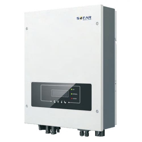
SOFAR Solar Inverter
Reads PV and grid values from SOFAR Solar inverters via Modbus RTU.
This template reads PV and grid values from SOFAR Solar inverters via Modbus RTU. It provides PV1 voltage, current, and power, three-phase grid measurements, grid frequency, output active power, and daily and total energy production.
- Protocol
- Modbus RTU
- Connection
- RS485, 9600 baud
- Registers
- 13, read only
- Brand
- SOFAR Solar
- Key readings
- PV1 voltage, current, power · A/B/C-phase voltage · A/B/C-phase current · Grid frequency · Output active power · Today and total production
- Last updated
Registers (13)
13 read, 0 write
| Name | Unit | Access | Address (Hidden until you enter your email) | Function (hidden) | Type (hidden) |
|---|---|---|---|---|---|
| PV1 voltage | V | Read | |||
| PV1 current | A | Read | |||
| PV1 power | kW | Read | |||
| Grid frequency | Hz | Read | |||
| Total production | kWh | Read | |||
| Output active power | kW | Read | |||
| Today production | kWh | Read | |||
| A-phase voltage | V | Read | |||
| B-phase voltage | V | Read | |||
| C-phase voltage | V | Read | |||
| A-phase current | A | Read | |||
| B-phase current | A | Read | |||
| C-phase current | A | Read |
Loading registers…
Send your device list
If a device is not in the library yet, we build the template for free as soon as we have the register data.
Use cases
- Monitor PV1 voltage, current, and power on a live cloud dashboard for your customer.
- Track daily and total energy production to verify system yield over time.
- Create an alert when grid frequency deviates from the expected range for more than five minutes.
- Compare three-phase voltage and current across A, B, and C phases to detect imbalance.
- Export historical production data as reports for maintenance visits or energy audits.
- Add multiple SOFAR Solar inverters on one RS485 bus and monitor them from a single dashboard.
Installation
Connect the ModbusCloud Gateway A and B terminals to the RS485 port on the SOFAR Solar inverter, observing correct polarity.
Set the inverter Modbus slave address to a unique value using the inverter display or configuration tool.
Confirm the inverter serial communication settings are 9600 baud, 8 data bits, 1 stop bit, no parity.
Import the SOFAR Solar Inverter template in the ModbusCloud platform and assign it to the correct gateway port.
Enter the configured Modbus slave address in the template settings and verify that live data appears on the dashboard.
Things to watch for
No data appears after connecting the gateway to the inverter. What should I check?
Verify that the RS485 A and B wires are not swapped. Confirm the slave address in ModbusCloud matches the address configured on the inverter. Make sure the baud rate is set to 9600 on both devices.
PV1 power or total production values look incorrect or extremely large. Why?
These registers use uint32 format across two consecutive registers. Ensure the template is imported without manual register edits. If you modified registers, check that the data type is set to uint32 and the register order matches the SOFAR Solar documentation.
Can I monitor multiple SOFAR Solar inverters on the same RS485 bus?
Yes. Assign each inverter a unique Modbus slave address and create a separate template instance in ModbusCloud for each address. All inverters share the same two-wire RS485 connection to the gateway.
The output active power value seems too low. Is there a scaling issue?
Output active power and PV1 power are expressed in kW in this template. Confirm you are not comparing kW values with W values from another source. The template applies the correct scaling automatically.
More SOFAR Solar templates
Want to see how it works?
