Yaskawa V1000
Compact frequency converter: frequency, current, power, fault history, run command and all parameters.
The Yaskawa V1000 is a compact frequency converter for pumps, fans, conveyors and machines up to 18.5 kW. This Modbus RTU template reads frequency, current, voltage, power, drive status, faults and maintenance monitors, and lets you start, stop and set the speed of the drive and change every parameter from ModbusCloud.
- Protocol
- Modbus RTU
- Connection
- RS485, 9600 baud
- Registers
- 675, read and write
- Brand
- Yaskawa
- Key readings
- Output frequency · Output current · Output voltage · DC bus voltage · Drive status · Fault history · Cumulative operation time
- Available commands
- Run command · Frequency reference · Acceleration and deceleration times · All parameters
- Compatible models
- V1000 compact vector control drive, all models (CIMR-VC and CIMR-VU, BA, 2A and 4A)
- Last updated
Registers (675)
673 read, 523 write
| Name | Unit | Access | Address (Hidden until you enter your email) | Function (hidden) | Type (hidden) |
|---|---|---|---|---|---|
| Frequency Reference (U1-01) | Hz | Read | |||
| Output Frequency (U1-02) | Hz | Read | |||
| Output Current (U1-03) | Read | ||||
| Control Mode (U1-04) | Read | ||||
| Motor Speed (U1-05) | Hz | Read | |||
| Output Voltage Reference (U1-06) | V | Read | |||
| DC Bus Voltage (U1-07) | V | Read | |||
| Output Power (U1-08) | Read | ||||
| Torque Reference (U1-09) | Read | ||||
| Input Terminal Status (U1-10) | Read | ||||
| Output Terminal Status (U1-11) | Read | ||||
| Drive Status (U1-12) | Read | ||||
| Terminal A1 Input Level (U1-13) | % | Read | |||
| Terminal A2 Input Level (U1-14) | % | Read | |||
| Output Frequency after Soft Starter (U1-16) | Hz | Read | |||
| oPE Fault Parameter (U1-18) | Read | ||||
| MEMOBUS/Modbus Error Code (U1-19) | Read | ||||
| Input Pulse Monitor (U1-24) | Hz | Read | |||
| Software No. (Flash) (U1-25) | Read | ||||
| Software No. (ROM) (U1-26) | Read | ||||
| Operator Message ID (U1-27) | Read | ||||
| Drive Message ID (U1-28) | Read | ||||
| Drive Status 1 | Read | ||||
| Fault Contents 1 | Read | ||||
| Data Link Status | Read | ||||
| Frequency Reference | Read | ||||
| Output Frequency | Read | ||||
| Output Voltage Reference | V | Read | |||
| Output Current | Read | ||||
| Output Power | Read | ||||
| Torque Reference | Read | ||||
| Fault Contents 2 | Read | ||||
| Alarm Contents 1 | Read | ||||
| Input Terminal Status | Read | ||||
| Drive Status 2 | Read | ||||
| Output Terminal Status | Read | ||||
| Frequency Reference Bias | % | Read | |||
| DC Bus Voltage | V | Read | |||
| Torque Monitor | % | Read | |||
| Product Code 1 | Read | ||||
| Product Code 2 | Read | ||||
| PID Feedback | % | Read | |||
| PID Input | % | Read | |||
| PID Output | % | Read | |||
| Communications Error Log | Read | ||||
| Output Frequency (r/min) | rpm | Read | |||
| Output Frequency (%) | % | Read | |||
| Alarm Code | Read | ||||
| Cumulative Operation Time (U4-01) High | Read | ||||
| Cumulative Operation Time (U4-01) Low | h | Read | |||
| Cooling Fan Operation Time (U4-03) High | Read | ||||
| Cooling Fan Operation Time (U4-03) Low | h | Read | |||
| Drive Rated Current | Read | ||||
| Motor Speed (r/min) | rpm | Read | |||
| Motor Speed (%) | % | Read | |||
| Option Code | Read | ||||
| Frequency Reference After Soft-starter (r/min) | rpm | Read | |||
| Frequency Reference After Soft-starter (%) | % | Read | |||
| Frequency Reference (r/min) | rpm | Read | |||
| Frequency Reference (%) | % | Read | |||
| oPE Error Number | Read | ||||
| Fault Contents 3 | Read | ||||
| Fault Contents 4 | Read | ||||
| Fault Contents 5 | Read | ||||
| Fault Contents 6 | Read | ||||
| Fault Contents 7 | Read | ||||
| Alarm Contents 2 | Read | ||||
| Alarm Contents 3 | Read | ||||
| Alarm Contents 4 | Read | ||||
| Alarm Contents 5 | Read | ||||
| CPF Contents 1 | Read | ||||
| CPF Contents 2 | Read | ||||
| Option Card Fault Contents | Read | ||||
| Output Current (Data Table) | Read | ||||
| Current Fault (U2-01) | Read | ||||
| Previous Fault (U2-02) | Read | ||||
| Frequency Reference at Previous Fault (U2-03) | Hz | Read | |||
| Output Frequency at Previous Fault (U2-04) | Hz | Read | |||
| Output Current at Previous Fault (U2-05) | Read | ||||
| Motor Speed at Previous Fault (U2-06) | Hz | Read | |||
| Output Voltage at Previous Fault (U2-07) | V | Read | |||
| DC Bus Voltage at Previous Fault (U2-08) | V | Read | |||
| Output Power at Previous Fault (U2-09) | kW | Read | |||
| Torque Reference at Previous Fault (U2-10) | % | Read | |||
| Input Terminal Status at Previous Fault (U2-11) | Read | ||||
| Output Terminal Status at Previous Fault (U2-12) | Read | ||||
| Drive Operation Status at Previous Fault (U2-13) | Read | ||||
| Cumulative Operation Time at Previous Fault (U2-14) | Read | ||||
| Soft Starter Speed Reference at Previous Fault (U2-15) | % | Read | |||
| Motor q-Axis Current at Previous Fault (U2-16) | Read | ||||
| Motor d-Axis Current at Previous Fault (U2-17) | Read | ||||
| Most Recent Fault (U3-01) | Read | ||||
| 2nd Most Recent Fault (U3-02) | Read | ||||
| 3rd Most Recent Fault (U3-03) | Read | ||||
| 4th Most Recent Fault (U3-04) | Read | ||||
| 5th Most Recent Fault (U3-05) | Read | ||||
| 6th Most Recent Fault (U3-06) | Read | ||||
| 7th Most Recent Fault (U3-07) | Read | ||||
| 8th Most Recent Fault (U3-08) | Read | ||||
| 9th Most Recent Fault (U3-09) | Read | ||||
| 10th Most Recent Fault (U3-10) | Read | ||||
| Cumulative Operation Time at Most Recent Fault (U3-11) | h | Read | |||
| Cumulative Operation Time at 2nd Most Recent Fault (U3-12) | h | Read | |||
| Cumulative Operation Time at 3rd Most Recent Fault (U3-13) | h | Read | |||
| Cumulative Operation Time at 4th Most Recent Fault (U3-14) | h | Read | |||
| Cumulative Operation Time at 5th Most Recent Fault (U3-15) | h | Read | |||
| Cumulative Operation Time at 6th Most Recent Fault (U3-16) | h | Read | |||
| Cumulative Operation Time at 7th Most Recent Fault (U3-17) | h | Read | |||
| Cumulative Operation Time at 8th Most Recent Fault (U3-18) | h | Read | |||
| Cumulative Operation Time at 9th Most Recent Fault (U3-19) | h | Read | |||
| Cumulative Operation Time at 10th Most Recent Fault (U3-20) | h | Read | |||
| Accumulated Operation Time (U4-01) | h | Read | |||
| Number of Run Commands (U4-02) | Read | ||||
| Cooling Fan Operation Time (U4-03) | h | Read | |||
| Cooling Fan Maintenance (U4-04) | % | Read | |||
| Capacitor Maintenance (U4-05) | % | Read | |||
| Soft Charge Bypass Relay Maintenance (U4-06) | % | Read | |||
| IGBT Maintenance (U4-07) | % | Read | |||
| Heatsink Temperature (U4-08) | °C | Read | |||
| LED Check (U4-09) | Read | ||||
| kWh, Lower 4 Digits (U4-10) | Read | ||||
| kWh, Upper 5 Digits (U4-11) | MWh | Read | |||
| Peak Hold Current (U4-13) | Read | ||||
| Peak Hold Output Frequency (U4-14) | Hz | Read | |||
| Motor Overload Estimate (oL1) (U4-16) | % | Read | |||
| Frequency Reference Source Selection (U4-18) | Read | ||||
| Frequency Reference from MEMOBUS/Modbus Comm. (U4-19) | Read | ||||
| MEMOBUS/Modbus Communications Reference (U4-22) | Read | ||||
| Option Card Reference (U4-23) | Read | ||||
| PID Feedback (U5-01) | % | Read | |||
| PID Input (U5-02) | % | Read | |||
| PID Output (U5-03) | % | Read | |||
| PID Setpoint (U5-04) | % | Read | |||
| PID Differential Feedback (U5-05) | % | Read | |||
| PID Adjusted Feedback (U5-06) | % | Read | |||
| Motor Secondary Current (Iq) (U6-01) | % | Read | |||
| Motor Excitation Current (ld) (U6-02) | % | Read | |||
| ASR Input (U6-03) | % | Read | |||
| ASR Output (U6-04) | % | Read | |||
| Output voltage reference (Vq) (U6-05) | Read | ||||
| Output Voltage Reference (Vd) (U6-06) | Read | ||||
| q-axis ACR Output (U6-07) | % | Read | |||
| d-Axis ACR Output (U6-08) | % | Read | |||
| Frequency Reference Bias (Up/Down 2) (U6-20) | % | Read | |||
| Offset Frequency (U6-21) | % | Read | |||
| DriveWorksEZ, Monitor 1 (U8-01) | % | Read | |||
| DriveWorksEZ, Monitor 2 (U8-02) | % | Read | |||
| DriveWorksEZ, Monitor 3 (U8-03) | % | Read | |||
| DriveWorksEZ, Monitor 4 (U8-04) | % | Read | |||
| DriveWorksEZ, Monitor 5 (U8-05) | % | Read | |||
| DriveWorksEZ, Monitor 6 (U8-06) | % | Read | |||
| DriveWorksEZ, Monitor 7 (U8-07) | % | Read | |||
| Operation Signals | Read and write | ||||
| Frequency Reference Command | Read and write | ||||
| Output Voltage Gain | % | Read and write | |||
| PID Target | % | Read and write | |||
| Analog Output Terminal AM Setting | Read and write | ||||
| Multi-Function Digital Output Settings | Read and write | ||||
| Pulse Output Terminal MP Setting | Hz | Read and write | |||
| Control Selection Setting | Read and write | ||||
| Enter Command (EEPROM) | Write | ||||
| Enter Command (RAM) | Write | ||||
| Language Selection (A1-00) | Read and write | ||||
| Access Level Selection (A1-01) | Read and write | ||||
| Control Method Selection (A1-02) | Read and write | ||||
| Initialize Parameters (A1-03) | Read and write | ||||
| Password (A1-04) | Read and write | ||||
| Password Setting (A1-05) | Read and write | ||||
| Application Preset (A1-06) | Read and write | ||||
| DriveWorksEZ Function Selection (A1-07) | Read and write | ||||
| User Parameters 1 (A2-01) | Read and write | ||||
| User Parameters 2 (A2-02) | Read and write | ||||
| User Parameters 3 (A2-03) | Read and write | ||||
| User Parameters 4 (A2-04) | Read and write | ||||
| User Parameters 5 (A2-05) | Read and write | ||||
| User Parameters 6 (A2-06) | Read and write | ||||
| User Parameters 7 (A2-07) | Read and write | ||||
| User Parameters 8 (A2-08) | Read and write | ||||
| User Parameters 9 (A2-09) | Read and write | ||||
| User Parameters 10 (A2-10) | Read and write | ||||
| User Parameters 11 (A2-11) | Read and write | ||||
| User Parameters 12 (A2-12) | Read and write | ||||
| User Parameters 13 (A2-13) | Read and write | ||||
| User Parameters 14 (A2-14) | Read and write | ||||
| User Parameters 15 (A2-15) | Read and write | ||||
| User Parameters 16 (A2-16) | Read and write | ||||
| User Parameters 17 (A2-17) | Read and write | ||||
| User Parameters 18 (A2-18) | Read and write | ||||
| User Parameters 19 (A2-19) | Read and write | ||||
| User Parameters 20 (A2-20) | Read and write | ||||
| User Parameters 21 (A2-21) | Read and write | ||||
| User Parameters 22 (A2-22) | Read and write | ||||
| User Parameters 23 (A2-23) | Read and write | ||||
| User Parameters 24 (A2-24) | Read and write | ||||
| User Parameters 25 (A2-25) | Read and write | ||||
| User Parameters 26 (A2-26) | Read and write | ||||
| User Parameters 27 (A2-27) | Read and write | ||||
| User Parameters 28 (A2-28) | Read and write | ||||
| User Parameters 29 (A2-29) | Read and write | ||||
| User Parameters 30 (A2-30) | Read and write | ||||
| User Parameters 31 (A2-31) | Read and write | ||||
| User Parameters 32 (A2-32) | Read and write | ||||
| User Parameter Automatic Selection (A2-33) | Read and write | ||||
| Frequency Reference Selection 1 (b1-01) | Read and write | ||||
| Run Command Selection (b1-02) | Read and write | ||||
| Stopping Method Selection (b1-03) | Read and write | ||||
| Reverse Operation Selection (b1-04) | Read and write | ||||
| LOCAL/REMOTE Run Selection (b1-07) | Read and write | ||||
| Run Command Selection while in Programming Mode (b1-08) | Read and write | ||||
| Phase Order Selection (b1-14) | Read and write | ||||
| Frequency Reference Selection 2 (b1-15) | Read and write | ||||
| Run Command Selection 2 (b1-16) | Read and write | ||||
| Run Command at Power Up (b1-17) | Read and write | ||||
| DC Injection Braking Start Frequency (b2-01) | Read and write | ||||
| DC Injection Braking Current (b2-02) | % | Read and write | |||
| DC Injection Braking Time/ DC Excitation Time at Start (b2-03) | Read and write | ||||
| DC Injection Braking Time at Stop (b2-04) | Read and write | ||||
| Magnetic Flux Compensation Value (b2-08) | % | Read and write | |||
| Short Circuit Brake Time at Start (b2-12) | Read and write | ||||
| Short Circuit Brake Time at Stop (b2-13) | Read and write | ||||
| Speed Search Selection at Start (b3-01) | Read and write | ||||
| Speed Search Deactivation Current (b3-02) | Read and write | ||||
| Speed Search Deceleration Time (b3-03) | Read and write | ||||
| Speed Search Delay Time (b3-05) | Read and write | ||||
| Output Current 1 during Speed Search (b3-06) | Read and write | ||||
| Current Control Gain during Speed Search (b3-08) | Read and write | ||||
| Speed Search Detection Compensation Gain (b3-10) | Read and write | ||||
| Bi-Directional Speed Search Selection (b3-14) | Read and write | ||||
| Speed Search Restart Current Level (b3-17) | % | Read and write | |||
| Speed Search Restart Detection Time (b3-18) | Read and write | ||||
| Number of Speed Search Restarts (b3-19) | Read and write | ||||
| Speed Search Method Selection (b3-24) | Read and write | ||||
| Speed Search Retry Interval Time (b3-25) | Read and write | ||||
| Speed Search Induced Voltage Level (b3-29) | % | Read and write | |||
| Timer Function On-Delay Time (b4-01) | Read and write | ||||
| Timer Function Off-Delay Time (b4-02) | Read and write | ||||
| PID Function Setting (b5-01) | Read and write | ||||
| Proportional Gain Setting (P) (b5-02) | Read and write | ||||
| Integral Time Setting (I) (b5-03) | Read and write | ||||
| Integral Limit Setting (b5-04) | Read and write | ||||
| Derivative Time (D) (b5-05) | Read and write | ||||
| PID Output Limit (b5-06) | Read and write | ||||
| PID Offset Adjustment (b5-07) | Read and write | ||||
| PID Primary Delay Time Constant (b5-08) | Read and write | ||||
| PID Output Level Selection (b5-09) | Read and write | ||||
| PID Output Gain Setting (b5-10) | Read and write | ||||
| PID Output Reverse Selection (b5-11) | Read and write | ||||
| PID Feedback Reference Missing Detection Selection (b5-12) | Read and write | ||||
| PID Feedback Loss Detection Level (b5-13) | % | Read and write | |||
| PID Feedback Loss Detection Time (b5-14) | Read and write | ||||
| PID Sleep Function Start Level (b5-15) | Read and write | ||||
| PID Sleep Delay Time (b5-16) | Read and write | ||||
| PID Accel/Decel Time (b5-17) | s | Read and write | |||
| PID Setpoint Selection (b5-18) | Read and write | ||||
| PID Setpoint Value (b5-19) | Read and write | ||||
| PID Setpoint Scaling (b5-20) | Read and write | ||||
| PID Output Lower Limit (b5-34) | Read and write | ||||
| PID Input Limit (b5-35) | Read and write | ||||
| PID Feedback High Detection Level (b5-36) | % | Read and write | |||
| PID Feedback High Level Detection Time (b5-37) | Read and write | ||||
| PID Setpoint / User Display (b5-38) | Read and write | ||||
| PID Setpoint Display Digits (b5-39) | Read and write | ||||
| Frequency Reference Monitor Content during PID (b5-40) | Read and write | ||||
| Reverse Operation Selection 2 by PID Output (b5-47) | Read and write | ||||
| Dwell Reference at Start (b6-01) | Read and write | ||||
| Dwell Time at Start (b6-02) | Read and write | ||||
| Dwell Frequency at Stop (b6-03) | Read and write | ||||
| Dwell Time at Stop (b6-04) | Read and write | ||||
| Energy Saving Control Selection (b8-01) | Read and write | ||||
| Energy Saving Gain (b8-02) | Read and write | ||||
| Energy Saving Control Filter Time Constant (b8-03) | Read and write | ||||
| Energy Saving Coefficient Value (b8-04) | Read and write | ||||
| Power Detection Filter Time (b8-05) | ms | Read and write | |||
| Search Operation Voltage Limit (b8-06) | % | Read and write | |||
| Acceleration Time 1 (C1-01) | Read and write | ||||
| Deceleration Time 1 (C1-02) | Read and write | ||||
| Acceleration Time 2 (C1-03) | Read and write | ||||
| Deceleration Time 2 (C1-04) | Read and write | ||||
| Acceleration Time 3 (Motor 2 Accel Time 1) (C1-05) | Read and write | ||||
| Deceleration Time 3 (Motor 2 Decel Time 1) (C1-06) | Read and write | ||||
| Acceleration Time 4 (Motor 2 Accel Time 2) (C1-07) | Read and write | ||||
| Deceleration Time 4 (Motor 2 Decel Time 2) (C1-08) | Read and write | ||||
| Fast-Stop Time (C1-09) | Read and write | ||||
| Accel/Decel Time Setting Units (C1-10) | Read and write | ||||
| Accel/Decel Time Switching Frequency (C1-11) | Read and write | ||||
| Accel/Decel Rate Frequency (C1-14) | Read and write | ||||
| S-Curve Characteristic at Accel Start (C2-01) | Read and write | ||||
| S-Curve Characteristic at Accel End (C2-02) | Read and write | ||||
| S-Curve Characteristic at Decel Start (C2-03) | Read and write | ||||
| S-Curve Characteristic at Decel End (C2-04) | Read and write | ||||
| Slip Compensation Gain (C3-01) | Read and write | ||||
| Slip Compensation Primary Delay Time (C3-02) | ms | Read and write | |||
| Slip Compensation Limit (C3-03) | % | Read and write | |||
| Slip Compensation Selection during Regeneration (C3-04) | Read and write | ||||
| Output Voltage Limit Operation Selection (C3-05) | Read and write | ||||
| Output Voltage Limit Level (C3-18) | Read and write | ||||
| Torque Compensation Gain (C4-01) | Read and write | ||||
| Torque Compensation Primary Delay Time (C4-02) | ms | Read and write | |||
| Torque Compensation at Forward Start (C4-03) | Read and write | ||||
| Torque Compensation at Reverse Start (C4-04) | Read and write | ||||
| Torque Compensation Time Constant (C4-05) | ms | Read and write | |||
| Torque Compensation Primary Delay Time 2 (C4-06) | ms | Read and write | |||
| ASR Proportional Gain 1 (C5-01) | Read and write | ||||
| ASR Integral Time 1 (C5-02) | Read and write | ||||
| ASR Proportional Gain 2 (C5-03) | Read and write | ||||
| ASR Integral Time 2 (C5-04) | Read and write | ||||
| ASR Limit (C5-05) | Read and write | ||||
| Drive Duty Selection (C6-01) | Read and write | ||||
| Carrier Frequency Selection (C6-02) | Read and write | ||||
| Carrier Frequency Upper Limit (C6-03) | Read and write | ||||
| Carrier Frequency Lower Limit (C6-04) | Read and write | ||||
| Carrier Frequency Proportional Gain (C6-05) | Read and write | ||||
| Frequency Reference 1 (d1-01) | Read and write | ||||
| Frequency Reference 2 (d1-02) | Read and write | ||||
| Frequency Reference 3 (d1-03) | Read and write | ||||
| Frequency Reference 4 (d1-04) | Read and write | ||||
| Frequency Reference 5 (d1-05) | Read and write | ||||
| Frequency Reference 6 (d1-06) | Read and write | ||||
| Frequency Reference 7 (d1-07) | Read and write | ||||
| Frequency Reference 8 (d1-08) | Read and write | ||||
| Frequency Reference 9 (d1-09) | Read and write | ||||
| Frequency Reference 10 (d1-10) | Read and write | ||||
| Frequency Reference 11 (d1-11) | Read and write | ||||
| Frequency Reference 12 (d1-12) | Read and write | ||||
| Frequency Reference 13 (d1-13) | Read and write | ||||
| Frequency Reference 14 (d1-14) | Read and write | ||||
| Frequency Reference 15 (d1-15) | Read and write | ||||
| Frequency Reference 16 (d1-16) | Read and write | ||||
| Jog Frequency Reference (d1-17) | Read and write | ||||
| Frequency Reference Upper Limit (d2-01) | Read and write | ||||
| Frequency Reference Lower Limit (d2-02) | Read and write | ||||
| Master Speed Reference Lower Limit (d2-03) | Read and write | ||||
| Jump Frequency 1 (d3-01) | Read and write | ||||
| Jump Frequency 2 (d3-02) | Read and write | ||||
| Jump Frequency 3 (d3-03) | Read and write | ||||
| Jump Frequency Width (d3-04) | Read and write | ||||
| Frequency Reference Hold Function Selection (d4-01) | Read and write | ||||
| Frequency Reference Bias Step (Up/Down 2) (d4-03) | Read and write | ||||
| Frequency Reference Bias Accel/Decel (Up/Down 2) (d4-04) | Read and write | ||||
| Frequency Reference Bias Operation Mode (Up/Down 2) (d4-05) | Read and write | ||||
| Frequency Reference Bias (Up/Down 2) (d4-06) | Read and write | ||||
| Analog Frequency Reference Fluctuation Limit (Up/Down 2) (d4-07) | Read and write | ||||
| Frequency Reference Bias Upper Limit (Up/Down 2) (d4-08) | Read and write | ||||
| Frequency Reference Bias Lower Limit (Up/Down 2) (d4-09) | Read and write | ||||
| Up/Down Frequency Reference Limit Selection (d4-10) | Read and write | ||||
| Offset Frequency 1 (d7-01) | Read and write | ||||
| Offset Frequency 2 (d7-02) | Read and write | ||||
| Offset Frequency 3 (d7-03) | Read and write | ||||
| Input Voltage Setting (E1-01) | V | Read and write | |||
| V/f Pattern Selection (E1-03) | Read and write | ||||
| Maximum Output Frequency (E1-04) | Read and write | ||||
| Maximum Output Voltage (E1-05) | Read and write | ||||
| Base Frequency (E1-06) | Read and write | ||||
| Middle Output Frequency (E1-07) | Read and write | ||||
| Middle Output Frequency Voltage (E1-08) | Read and write | ||||
| Minimum Output Frequency (E1-09) | Read and write | ||||
| Minimum Output Frequency Voltage (E1-10) | Read and write | ||||
| Middle Output Frequency 2 (E1-11) | Read and write | ||||
| Middle Output Frequency Voltage 2 (E1-12) | Read and write | ||||
| Base Voltage (E1-13) | Read and write | ||||
| Motor Rated Current (E2-01) | Read and write | ||||
| Motor Rated Slip (E2-02) | Read and write | ||||
| Motor No-Load Current (E2-03) | Read and write | ||||
| Number of Motor Poles (E2-04) | Read and write | ||||
| Motor Line-to-Line Resistance (E2-05) | Read and write | ||||
| Motor Leakage Inductance (E2-06) | Read and write | ||||
| Motor Iron-Core Saturation Coefficient 1 (E2-07) | Read and write | ||||
| Motor Iron-Core Saturation Coefficient 2 (E2-08) | Read and write | ||||
| Motor Mechanical Loss (E2-09) | Read and write | ||||
| Motor Iron Loss for Torque Compensation (E2-10) | Read and write | ||||
| Motor Rated Output (E2-11) | Read and write | ||||
| Motor Iron-Core Saturation Coefficient 3 (E2-12) | Read and write | ||||
| Motor 2 Control Method (E3-01) | Read and write | ||||
| Motor 2 Max Output Frequency (E3-04) | Read and write | ||||
| Motor 2 Max Voltage (E3-05) | Read and write | ||||
| Motor 2 Base Frequency (E3-06) | Read and write | ||||
| Motor 2 Mid Output Freq. (E3-07) | Read and write | ||||
| Motor 2 Mid Output Freq. Voltage (E3-08) | Read and write | ||||
| Motor 2 Min. Output Freq. (E3-09) | Read and write | ||||
| Motor 2 Min. Output Freq. Voltage (E3-10) | Read and write | ||||
| Motor 2 Mid Output Frequency 2 (E3-11) | Read and write | ||||
| Motor 2 Mid Output Frequency Voltage 2 (E3-12) | Read and write | ||||
| Motor 2 Base Voltage (E3-13) | Read and write | ||||
| Motor 2 Rated Current (E4-01) | Read and write | ||||
| Motor 2 Rated Slip (E4-02) | Read and write | ||||
| Motor 2 Rated No- Load Current (E4-03) | Read and write | ||||
| Motor 2 Motor Poles (E4-04) | Read and write | ||||
| Motor 2 Line-to- Line Resistance (E4-05) | Read and write | ||||
| Motor 2 Leakage Inductance (E4-06) | Read and write | ||||
| Motor 2 Motor Iron- Core Saturation Coefficient 1 (E4-07) | Read and write | ||||
| Motor 2 Motor Iron- Core Saturation Coefficient 2 (E4-08) | Read and write | ||||
| Motor 2 Mechanical Loss (E4-09) | Read and write | ||||
| Motor 2 Iron Loss (E4-10) | Read and write | ||||
| Motor 2 Rated Capacity (E4-11) | Read and write | ||||
| Motor 2 Iron-Core Saturation Coefficient 3 (E4-12) | Read and write | ||||
| Motor Code Selection (for PM motor) (E5-01) | Read and write | ||||
| Motor Rated Capacity (for PM motor) (E5-02) | Read and write | ||||
| Motor Rated Current (E5-03) | Read and write | ||||
| Motor Poles (E5-04) | Read and write | ||||
| Motor Stator Resistance (E5-05) | Read and write | ||||
| Motor d Axis Inductance (E5-06) | Read and write | ||||
| Motor q Axis Inductance (E5-07) | Read and write | ||||
| Motor Induction Voltage Constant 1 (E5-09) | Read and write | ||||
| Motor Induction Voltage Constant 2 (E5-24) | Read and write | ||||
| Current Detection Delay Time (E5-39) | Read and write | ||||
| Operation Selection at PG Open Circuit (PGo) (F1-02) | Read and write | ||||
| Operation Selection at Overspeed (oS) (F1-03) | Read and write | ||||
| Operation Selection at Deviation (F1-04) | Read and write | ||||
| Overspeed Detection Level (F1-08) | % | Read and write | |||
| Overspeed Detection Delay Time (F1-09) | Read and write | ||||
| Excessive Speed Deviation Detection Level (F1-10) | % | Read and write | |||
| Excessive Speed Deviation Detection Delay Time (F1-11) | Read and write | ||||
| PG Open-Circuit Detection Time (F1-14) | Read and write | ||||
| Communications Error operation Selection (F6-01) | Read and write | ||||
| External fault from comm. option selection (F6-02) | Read and write | ||||
| External fault from comm. option operation selection (F6-03) | Read and write | ||||
| Bus Error Detection Time (F6-04) | Read and write | ||||
| NetRef/ComRef Function Selection (F6-07) | Read and write | ||||
| Reset Communication Parameters (F6-08) | Read and write | ||||
| CC-Link Node Address (F6-10) | Read and write | ||||
| CC-Link communications speed (F6-11) | Read and write | ||||
| BUS Error Auto Reset (F6-14) | Read and write | ||||
| MECHATROLINK Station Address (F6-20) | Read and write | ||||
| MECHATROLINK Frame Size (F6-21) | Read and write | ||||
| MECHATROLINK Link Speed (F6-22) | Read and write | ||||
| MECHATROLINK Monitor Selection (E) (F6-23) | Read and write | ||||
| MECHATROLINK Monitor Selection (F) (F6-24) | Read and write | ||||
| Operation at MECHATROLINK Watchdog Error (E5) (F6-25) | Read and write | ||||
| MECHATROLINK bUS Errors Detected (F6-26) | Read and write | ||||
| PROFIBUS node address (F6-30) | Read and write | ||||
| PROFIBUS Clear Mode Selection (F6-31) | Read and write | ||||
| PROFIBUS Data Format Selections (F6-32) | Read and write | ||||
| CANopen Node ID selection (F6-35) | Read and write | ||||
| CANopen Communications speed (F6-36) | Read and write | ||||
| CompoNet Node ID (F6-40) | Read and write | ||||
| CompoNet Speed (F6-41) | Read and write | ||||
| DeviceNet MAC Address (F6-50) | Read and write | ||||
| Device Net Communications Speed (F6-51) | Read and write | ||||
| DeviceNet PCA setting (F6-52) | Read and write | ||||
| DeviceNet PPA setting (F6-53) | Read and write | ||||
| DeviceNet Idle Mode Fault Detection (F6-54) | Read and write | ||||
| DeviceNet Baud Rate Monitor (F6-55) | Read and write | ||||
| DeviceNet Speed Scaling Factor (F6-56) | Read and write | ||||
| DeviceNet Current Scaling Factor (F6-57) | Read and write | ||||
| DeviceNet Torque Scaling Factor (F6-58) | Read and write | ||||
| DeviceNet Power Scaling Factor (F6-59) | Read and write | ||||
| DeviceNet Voltage Scaling Factor (F6-60) | Read and write | ||||
| DeviceNet Time Scaling Factor (F6-61) | Read and write | ||||
| DeviceNet Heartbeat Interval (F6-62) | Read and write | ||||
| Digital Input Terminal S1 Function Selection (H1-01) | Read and write | ||||
| Digital Input Terminal S2 Function Selection (H1-02) | Read and write | ||||
| Digital Input Terminal S3 Function Selection (H1-03) | Read and write | ||||
| Digital Input Terminal S4 Function Selection (H1-04) | Read and write | ||||
| Digital Input Terminal S5 Function Selection (H1-05) | Read and write | ||||
| Digital Input Terminal S6 Function Selection (H1-06) | Read and write | ||||
| Digital Input Terminal S7 Function Selection (H1-07) | Read and write | ||||
| Terminal MA, MB and MC Function Selection (relay) (H2-01) | Read and write | ||||
| Terminal P1 Function Selection (opencollector) (H2-02) | Read and write | ||||
| Terminal P2 Function Selection (opencollector) (H2-03) | Read and write | ||||
| Watt Hour Output Unit Selection (H2-06) | Read and write | ||||
| Terminal A1 Signal Level Selection (H3-01) | Read and write | ||||
| Terminal A1 Function Selection (H3-02) | Read and write | ||||
| Terminal A1 Gain Setting (H3-03) | Read and write | ||||
| Terminal A1 Bias Setting (H3-04) | Read and write | ||||
| Terminal A2 Signal Level Selection (H3-09) | Read and write | ||||
| Terminal A2 Function Selection (H3-10) | Read and write | ||||
| Terminal A2 Gain Setting (H3-11) | Read and write | ||||
| Terminal A2 Bias Setting (H3-12) | Read and write | ||||
| Analog Input Filter Time Constant (H3-13) | Read and write | ||||
| Analog Input Terminal Enable Selection (H3-14) | Read and write | ||||
| Terminal A1 Offset (H3-16) | Read and write | ||||
| Terminal A2 offset (H3-17) | Read and write | ||||
| Multi-Function Analog Output Terminal AM (H4-01) | Read and write | ||||
| Multi-Function Analog Output Terminal AM Gain (H4-02) | Read and write | ||||
| Multi-Function Analog Output Terminal AM Bias (H4-03) | Read and write | ||||
| Drive Node Address (H5-01) | Read and write | ||||
| Communication Speed Selection (H5-02) | Read and write | ||||
| Communication Parity Selection (H5-03) | Read and write | ||||
| Stopping Method After Communication Error (H5-04) | Read and write | ||||
| Communication Fault Detection Selection (H5-05) | Read and write | ||||
| Drive Transmit Wait Time (H5-06) | ms | Read and write | |||
| RTS Control Selection (H5-07) | Read and write | ||||
| CE Detection Time (H5-09) | Read and write | ||||
| Unit Selection for MEMOBUS/Modbus Register 0025H (H5-10) | Read and write | ||||
| Communications ENTER Function Selection (H5-11) | Read and write | ||||
| Run Command Method Selection (H5-12) | Read and write | ||||
| Pulse Train Input Terminal RP Function Selection (H6-01) | Read and write | ||||
| Pulse Train Input Scaling (H6-02) | Hz | Read and write | |||
| Pulse Train Input Gain (H6-03) | Read and write | ||||
| Pulse Train Input Bias (H6-04) | Read and write | ||||
| Pulse Train Input Filter Time (H6-05) | Read and write | ||||
| Pulse Train Monitor Terminal MP Selection (H6-06) | Read and write | ||||
| Pulse Train Monitor Scaling (H6-07) | Hz | Read and write | |||
| Motor Overload Protection Selection (L1-01) | Read and write | ||||
| Motor Overload Protection Time (L1-02) | Read and write | ||||
| Motor Overheat Alarm Operation Selection (PTC input) (L1-03) | Read and write | ||||
| Motor Overheat Fault Operation Selection (PTC input) (L1-04) | Read and write | ||||
| Motor Temperature Input Filter Time (PTC input) (L1-05) | Read and write | ||||
| Continuous Electrothermal Operation Selection (L1-13) | Read and write | ||||
| Leakage Current Filter Time (L1-22) | Read and write | ||||
| Leakage Current Filter Time (L1-23) | Read and write | ||||
| Momentary Power Loss Operation Selection (L2-01) | Read and write | ||||
| Momentary Power Loss Ride- Thru Time (L2-02) | Read and write | ||||
| Momentary Power Loss Minimum Baseblock Time (L2-03) | Read and write | ||||
| Momentary Power Loss Voltage Recovery Ramp Time (L2-04) | Read and write | ||||
| Undervoltage Detection Level (Uv) (L2-05) | Read and write | ||||
| KEB Deceleration Time (L2-06) | Read and write | ||||
| KEB Acceleration Time (L2-07) | Read and write | ||||
| KEB Start Output Frequency Reduction (L2-08) | % | Read and write | |||
| Desired DC Bus Voltage during KEB (L2-11) | Read and write | ||||
| Stall Prevention Selection during Acceleration (L3-01) | Read and write | ||||
| Stall Prevention Level during Acceleration (L3-02) | Read and write | ||||
| Stall Prevention Limit during Acceleration (L3-03) | % | Read and write | |||
| Stall Prevention Selection during Deceleration (L3-04) | Read and write | ||||
| Stall Prevention Selection during Run (L3-05) | Read and write | ||||
| Stall Prevention Level during Run (L3-06) | Read and write | ||||
| ov Suppression Function Selection (L3-11) | Read and write | ||||
| OV Suppression and Stall Prevention DC Bus Voltage (L3-17) | V | Read and write | |||
| Main Power Circuit Voltage Adjustment Gain (L3-20) | Read and write | ||||
| Accel/Decel Rate Calculation Gain (L3-21) | Read and write | ||||
| Decel Time at Stall Prevention during Accel (L3-22) | Read and write | ||||
| Auto Reduction for Stall Prevention during Run (L3-23) | Read and write | ||||
| Motor Acceleration Time for Inertia Calculations (L3-24) | Read and write | ||||
| Load Inertia Ratio (L3-25) | Read and write | ||||
| Speed Agreement Detection Level (L4-01) | Read and write | ||||
| Speed Agreement Detection Width (L4-02) | Read and write | ||||
| Speed Agreement Detection Level (+/-) (L4-03) | Read and write | ||||
| Speed Agreement Detection Width (+/-) (L4-04) | Read and write | ||||
| Frequency Reference Loss Detection Selection (L4-05) | Read and write | ||||
| Frequency Reference at Reference Loss (L4-06) | Read and write | ||||
| Frequency Detection Conditions (L4-07) | Read and write | ||||
| Speed Agreement Detection Conditions (L4-08) | Read and write | ||||
| Number of Auto Restart Attempts (L5-01) | Read and write | ||||
| Auto Restart Operation Selection (L5-02) | Read and write | ||||
| Fault Reset Interval Time (L5-04) | Read and write | ||||
| Fault Reset Operation Selection (L5-05) | Read and write | ||||
| Torque Detection Selection 1 (L6-01) | Read and write | ||||
| Torque Detection Level 1 (L6-02) | % | Read and write | |||
| Torque Detection Time 1 (L6-03) | Read and write | ||||
| Torque Detection Selection 2 (L6-04) | Read and write | ||||
| Torque Detection Level 2 (L6-05) | % | Read and write | |||
| Torque Detection Time 2 (L6-06) | Read and write | ||||
| Mechanical Weakening (oL5) Detection Operation (L6-08) | Read and write | ||||
| Mechanical Weakening Detection Speed Level (L6-09) | Read and write | ||||
| Mechanical Weakening Detection Time (L6-10) | Read and write | ||||
| Mechanical Weakening Detection Start Time (L6-11) | Read and write | ||||
| Forward Torque Limit (L7-01) | % | Read and write | |||
| Reverse Torque Limit (L7-02) | % | Read and write | |||
| Forward Regenerative Torque Limit (L7-03) | % | Read and write | |||
| Reverse Regenerative Torque Limit (L7-04) | % | Read and write | |||
| Torque Limit Integral Time Constant (L7-06) | ms | Read and write | |||
| Torque Limit Control Method during Accel/Decel (L7-07) | Read and write | ||||
| Internal Braking Resistor Protection (ERF type) (L8-01) | Read and write | ||||
| Overheat Alarm Level (L8-02) | Read and write | ||||
| Overheat Pre-Alarm Operation Selection (L8-03) | Read and write | ||||
| Input Phase Loss Protection Selection (L8-05) | Read and write | ||||
| Output Phase Loss Protection Selection (L8-07) | Read and write | ||||
| Output Ground Fault Detection Selection (L8-09) | Read and write | ||||
| Heatsink Cooling Fan Operation Selection (L8-10) | Read and write | ||||
| Heatsink Cooling Fan Operation Delay Time (L8-11) | s | Read and write | |||
| Ambient Temperature Setting (L8-12) | °C | Read and write | |||
| oL2 Characteristics Selection at Low Speeds (L8-15) | Read and write | ||||
| Soft Current Limit Selection (L8-18) | Read and write | ||||
| Frequency Reduction Rate during oH Pre-Alarm (L8-19) | Read and write | ||||
| Current Unbalance Detection (LF2) (L8-29) | Read and write | ||||
| Installation Method Selection (L8-35) | Read and write | ||||
| Carrier Frequency Reduction (L8-38) | Read and write | ||||
| Carrier Frequency Reduction Time (L8-40) | Read and write | ||||
| High Current Alarm Selection (L8-41) | Read and write | ||||
| STo Fault Detection Level (L8-51) | Read and write | ||||
| STo Deviation Detection (L8-54) | Read and write | ||||
| Hunting Prevention Selection (n1-01) | Read and write | ||||
| Hunting Prevention Gain Setting (n1-02) | Read and write | ||||
| Hunting Prevention Time Constant (n1-03) | Read and write | ||||
| Hunting Prevention Gain while in Reverse (n1-05) | Read and write | ||||
| Speed Feedback Detection Control (AFR) Gain (n2-01) | Read and write | ||||
| Speed Feedback Detection Control (AFR) Time Constant (n2-02) | ms | Read and write | |||
| Speed Feedback Detection Control (AFR) Time Constant 2 (n2-03) | ms | Read and write | |||
| High-Slip Braking Deceleration Frequency Width (n3-01) | % | Read and write | |||
| High-Slip Braking Current Limit (n3-02) | % | Read and write | |||
| High-Slip Braking Dwell Time at Stop (n3-03) | Read and write | ||||
| High-Slip Braking Overload Time (n3-04) | s | Read and write | |||
| Overexcitation Deceleration Gain (n3-13) | Read and write | ||||
| High-Slip Suppression Current Level (n3-21) | % | Read and write | |||
| Overexcitation Operation Selection (n3-23) | Read and write | ||||
| Line-to-Line Motor Resistance Online Tuning (n6-01) | Read and write | ||||
| Speed Feedback Detection Control Gain (n8-45) | Read and write | ||||
| Pull-In Current Compensation Time Constant (n8-47) | Read and write | ||||
| Pull-In Current (n8-48) | % | Read and write | |||
| d-Axis Current for High- Efficiency Control (n8-49) | % | Read and write | |||
| Acceleration Pull-In Current (n8-51) | % | Read and write | |||
| Voltage Error Compensation Time Constant (n8-54) | Read and write | ||||
| Load Inertia (n8-55) | Read and write | ||||
| Output Voltage Limit (n8-62) | Read and write | ||||
| Output Voltage Limit Gain 1 (n8-63) | Read and write | ||||
| Speed Feedback Gain during ov Suppression (n8-65) | Read and write | ||||
| Output Voltage Limit Gain 2 (n8-68) | Read and write | ||||
| Output Voltage Limit Selection (n8-87) | Read and write | ||||
| Output Voltage Limit Switching Current Level (n8-88) | % | Read and write | |||
| Output Voltage Limit Switching Current Hysteresis Width (n8-89) | % | Read and write | |||
| Output Voltage Limit Switching Speed (n8-90) | % | Read and write | |||
| Id Limit for Output Voltage Limit Control (n8-91) | % | Read and write | |||
| Drive Mode Unit Monitor Selection (o1-01) | Read and write | ||||
| User Monitor Selection After Power Up (o1-02) | Read and write | ||||
| Digital Operator Display Selection (o1-03) | Read and write | ||||
| LCD Contrast Control (o1-05) | Read and write | ||||
| Frequency Reference Setting and User-Set Display (o1-10) | Read and write | ||||
| Frequency Reference Setting / Decimal Display (o1-11) | Read and write | ||||
| LO/RE Key Function Selection (o2-01) | Read and write | ||||
| STOP Key Function Selection (o2-02) | Read and write | ||||
| User Parameter Default Value (o2-03) | Read and write | ||||
| Drive Model Selection (o2-04) | Read and write | ||||
| Frequency Reference Setting Method Selection (o2-05) | Read and write | ||||
| Operation when Digital Operator Disconnected (o2-06) | Read and write | ||||
| Motor Direction at Power Up with Operator (o2-07) | Read and write | ||||
| Copy Function Selection (o3-01) | Read and write | ||||
| Copy Allowed Selection (o3-02) | Read and write | ||||
| Accumulated Operation Time Setting (o4-01) | Read and write | ||||
| Accumulated Operation Time Selection (o4-02) | Read and write | ||||
| Cooling Fan Operation Time Setting (o4-03) | Read and write | ||||
| Capacitor Maintenance Setting (o4-05) | % | Read and write | |||
| DC Bus Pre-Charge Relay Maintenance Setting (o4-07) | % | Read and write | |||
| IGBT Maintenance Setting (o4-09) | % | Read and write | |||
| U2, U3 Initialization (o4-11) | Read and write | ||||
| kWh Monitor Initialization (o4-12) | Read and write | ||||
| Number of Run Commands Initialize Selection (o4-13) | Read and write | ||||
| DriveWorksEZ Connection Parameter 1 (upper) (r1-01) | Read and write | ||||
| DriveWorksEZ Connection Parameter 1 (lower) (r1-02) | Read and write | ||||
| DriveWorksEZ Connection Parameter 2 (upper) (r1-03) | Read and write | ||||
| DriveWorksEZ Connection Parameter 2 (lower) (r1-04) | Read and write | ||||
| DriveWorksEZ Connection Parameter 3 (upper) (r1-05) | Read and write | ||||
| DriveWorksEZ Connection Parameter 3 (lower) (r1-06) | Read and write | ||||
| DriveWorksEZ Connection Parameter 4 (upper) (r1-07) | Read and write | ||||
| DriveWorksEZ Connection Parameter 4 (lower) (r1-08) | Read and write | ||||
| DriveWorksEZ Connection Parameter 5 (upper) (r1-09) | Read and write | ||||
| DriveWorksEZ Connection Parameter 5 (lower) (r1-10) | Read and write | ||||
| DriveWorksEZ Connection Parameter 6 (upper) (r1-11) | Read and write | ||||
| DriveWorksEZ Connection Parameter 6 (lower) (r1-12) | Read and write | ||||
| DriveWorksEZ Connection Parameter 7 (upper) (r1-13) | Read and write | ||||
| DriveWorksEZ Connection Parameter 7 (lower) (r1-14) | Read and write | ||||
| DriveWorksEZ Connection Parameter 8 (upper) (r1-15) | Read and write | ||||
| DriveWorksEZ Connection Parameter 8 (lower) (r1-16) | Read and write | ||||
| DriveWorksEZ Connection Parameter 9 (upper) (r1-17) | Read and write | ||||
| DriveWorksEZ Connection Parameter 9 (lower) (r1-18) | Read and write | ||||
| DriveWorksEZ Connection Parameter 10 (upper) (r1-19) | Read and write | ||||
| DriveWorksEZ Connection Parameter 10 (lower) (r1-20) | Read and write | ||||
| DriveWorksEZ Connection Parameter 11 (upper) (r1-21) | Read and write | ||||
| DriveWorksEZ Connection Parameter 11 (lower) (r1-22) | Read and write | ||||
| DriveWorksEZ Connection Parameter 12 (upper) (r1-23) | Read and write | ||||
| DriveWorksEZ Connection Parameter 12 (lower) (r1-24) | Read and write | ||||
| DriveWorksEZ Connection Parameter 13 (upper) (r1-25) | Read and write | ||||
| DriveWorksEZ Connection Parameter 13 (lower) (r1-26) | Read and write | ||||
| DriveWorksEZ Connection Parameter 14 (upper) (r1-27) | Read and write | ||||
| DriveWorksEZ Connection Parameter 14 (lower) (r1-28) | Read and write | ||||
| DriveWorksEZ Connection Parameter 15 (upper) (r1-29) | Read and write | ||||
| DriveWorksEZ Connection Parameter 15 (lower) (r1-30) | Read and write | ||||
| DriveWorksEZ Connection Parameter 16 (upper) (r1-31) | Read and write | ||||
| DriveWorksEZ Connection Parameter 16 (lower) (r1-32) | Read and write | ||||
| DriveWorksEZ Connection Parameter 17 (upper) (r1-33) | Read and write | ||||
| DriveWorksEZ Connection Parameter 17 (lower) (r1-34) | Read and write | ||||
| DriveWorksEZ Connection Parameter 18 (upper) (r1-35) | Read and write | ||||
| DriveWorksEZ Connection Parameter 18 (lower) (r1-36) | Read and write | ||||
| DriveWorksEZ Connection Parameter 19 (upper) (r1-37) | Read and write | ||||
| DriveWorksEZ Connection Parameter 19 (lower) (r1-38) | Read and write | ||||
| DriveWorksEZ Connection Parameter 20 (upper) (r1-39) | Read and write | ||||
| DriveWorksEZ Connection Parameter 20 (lower) (r1-40) | Read and write | ||||
| Motor Selection 1/2 (T1-00) | Read and write | ||||
| Auto-Tuning Mode Selection (T1-01) | Read and write | ||||
| Motor Rated Power (T1-02) | Read and write | ||||
| Motor Rated Voltage (T1-03) | Read and write | ||||
| Motor Rated Current (T1-04) | Read and write | ||||
| Motor Base Frequency (T1-05) | Read and write | ||||
| Number of Motor Poles (T1-06) | Read and write | ||||
| Motor Base Speed (T1-07) | Read and write | ||||
| Motor Iron Loss (T1-11) | Read and write |
Loading registers…
Send your device list
If a device is not in the library yet, we build the template for free as soon as we have the register data.
Use cases
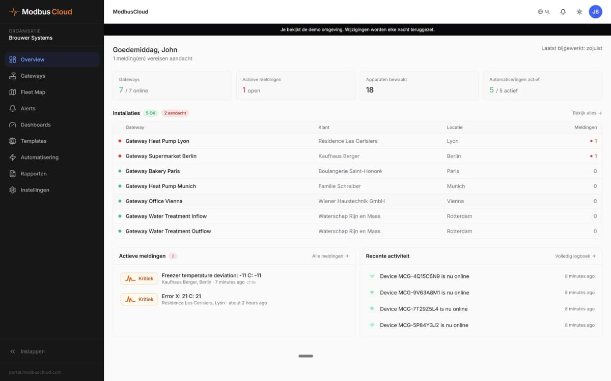
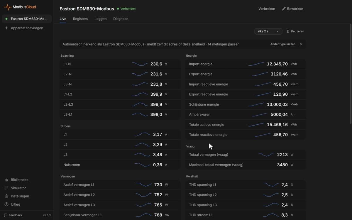
- Show output frequency, current and DC bus voltage of a pump or fan drive on a dashboard.
- Get an email when the fault bit in the drive status turns on, with the fault name from the fault history.
- Track cumulative operation time and capacitor and fan maintenance to plan service before a part fails.
- Start, stop and set the speed of a fan from an automation once writing is switched on.
- Change acceleration times, frequency limits or PID settings remotely without a keypad on site.
Installation
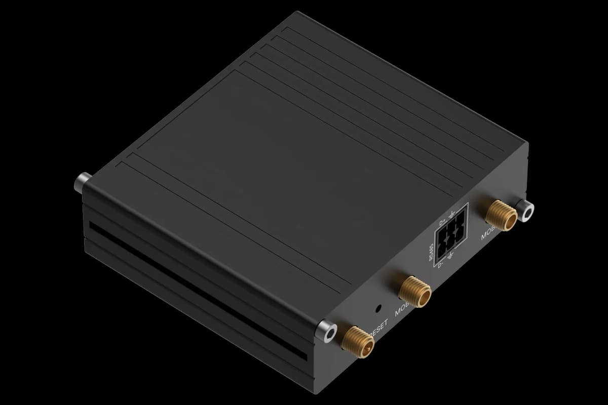
Connect R+ and S+ to RS485 A and R- and S- to RS485 B of the ModbusCloud Gateway (2-wire), and switch on the termination resistor on the last drive of the line.
Set H5-01 to a free node address, H5-02 to the bus speed and H5-03 to the parity, then cycle power to the drive.
To control the drive over the bus as well, set b1-01 and b1-02 to 2 (MEMOBUS communications).
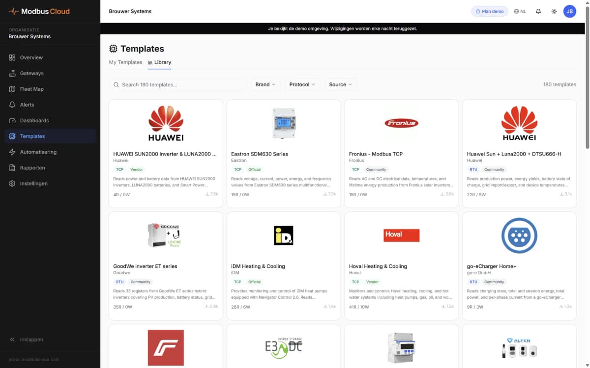
In ModbusCloud, add a Modbus device (RTU) with the same address and settings, import this template and check that output frequency and current arrive.
Things to watch for
The drive does not answer after changing the address.
The settings of H5-01 to H5-03 only take effect after the drive is powered off and on again. The factory node address is 1F hex, which is 31, and node address 0 gives no answer at all.
Parameter values look 10 or 100 times too large.
Parameters are read as whole numbers and the template uses scale 1. The comment of each register gives the setting resolution, for example 0.1 s; compare one value with the keypad and set the matching scale on the registers you use.
A written parameter is not kept after a power cycle.
With H5-11 = 0 the drive only takes over new values after an Enter command. Write 0 to the Enter Command (EEPROM) register to store them; the Enter Command (RAM) register keeps them only until power off. With the default H5-11 = 1 changes are active immediately.
Can I start and stop the drive from ModbusCloud?
Yes, once writing registers is switched on for your gateway and b1-02 is set to 2. Bit 0 of the Operation Signals register is the run command. A wrong value can start or stop a motor, so agree on remote control on site first.
More Yaskawa templates

Want to see how it works?