








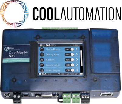
CoolMasterNet
Controls VRF/VRV HVAC units via CoolMasterNet gateway over Modbus TCP.
Template for controlling VRF/VRV HVAC indoor units via the CoolAutomation CoolMasterNet or CoolLinkHub gateway over Modbus TCP. Supports on/off switching, operation mode, fan speed, and temperature setpoint for up to three indoor units (VA1, VA2, VA3).
- Protocol
- Modbus TCP
- Connection
- Ethernet, Modbus TCP
- Registers
- 11, read and write
- Brand
- CoolAutomation
- Available commands
- On/Off (VA1 to VA3) · Operation Mode (VA1 to VA3) · Fan Speed (VA1 to VA3) · Set Temp (VA1, VA3)
- Compatible models
- CoolMasterNet · CoolLinkHub
- Last updated
Registers (11)
0 read, 11 write
| Name | Unit | Access | Address (Hidden until you enter your email) | Function (hidden) | Type (hidden) |
|---|---|---|---|---|---|
| VA1 On Off | Write | ||||
| VA2 On Off | Write | ||||
| VA3 On Off | Write | ||||
| VA1 Operation Mode | Write | ||||
| VA2 Operation Mode | Write | ||||
| VA1 Set Temp | °C | Write | |||
| VA1 Fan Speed | Write | ||||
| VA2 Fan Speed | Write | ||||
| VA3 Operation Mode | Write | ||||
| VA3 Fan Speed | Write | ||||
| VA3 Set Temp | °C | Write |
Loading registers…
Send your device list
If a device is not in the library yet, we build the template for free as soon as we have the register data.
Use cases
- Control on/off state of up to three VRF indoor units remotely from the ModbusCloud dashboard.
- Switch operation modes between cooling, heating, and fan only for each indoor unit on a scheduled basis.
- Adjust temperature setpoints for VA1 and VA3 units to maintain comfort levels across different zones.
- Monitor last-sent fan speed and mode commands per unit to verify automation rules are executing correctly.
- Create automation rules that turn off all HVAC units outside of business hours to reduce energy consumption.
Installation
Connect the CoolMasterNet or CoolLinkHub to the same local network as the ModbusCloud Gateway using an Ethernet cable.
Ensure the CoolMasterNet or CoolLinkHub has Modbus TCP enabled and note its IP address and TCP port (default is 502).
If using a CoolLinkHub, verify that a CoolPlug module is installed on each indoor unit you want to control.
Import the CoolAutomation CoolMasterNet template from the ModbusCloud template library into your project.
Set the target IP address, TCP port, and Modbus unit ID in the ModbusCloud gateway configuration to match the CoolMasterNet or CoolLinkHub settings.
Send a test on/off command to VA1 and confirm the indoor unit responds before configuring the remaining units.
Things to watch for
Why can I not read current room temperature or unit status from this template?
All registers in this template are write-only. The CoolMasterNet exposes command registers that accept control values but do not return read-back data on the same addresses. Check the CoolMasterNet Modbus register documentation for separate read registers if available.
Why is the VA2 temperature setpoint missing from the template?
The register map provided for this template does not include a setpoint register for VA2. This is a limitation of the current register map, not a ModbusCloud restriction. Contact CoolAutomation support if you need the VA2 setpoint address.
The VA2 unit does not respond to on/off commands. What should I check?
Make sure you are using template version 1.0.2 or later. Earlier versions used an incorrect register address for VA2 on/off. The corrected address is register 35.
What baud rate or serial settings do I need for this template?
This template uses Modbus TCP, so serial settings like baud rate do not apply. Ensure the CoolMasterNet or CoolLinkHub and the ModbusCloud gateway are on the same IP subnet and that TCP port 502 (or your configured port) is not blocked by a firewall.





Want to see how it works?
