








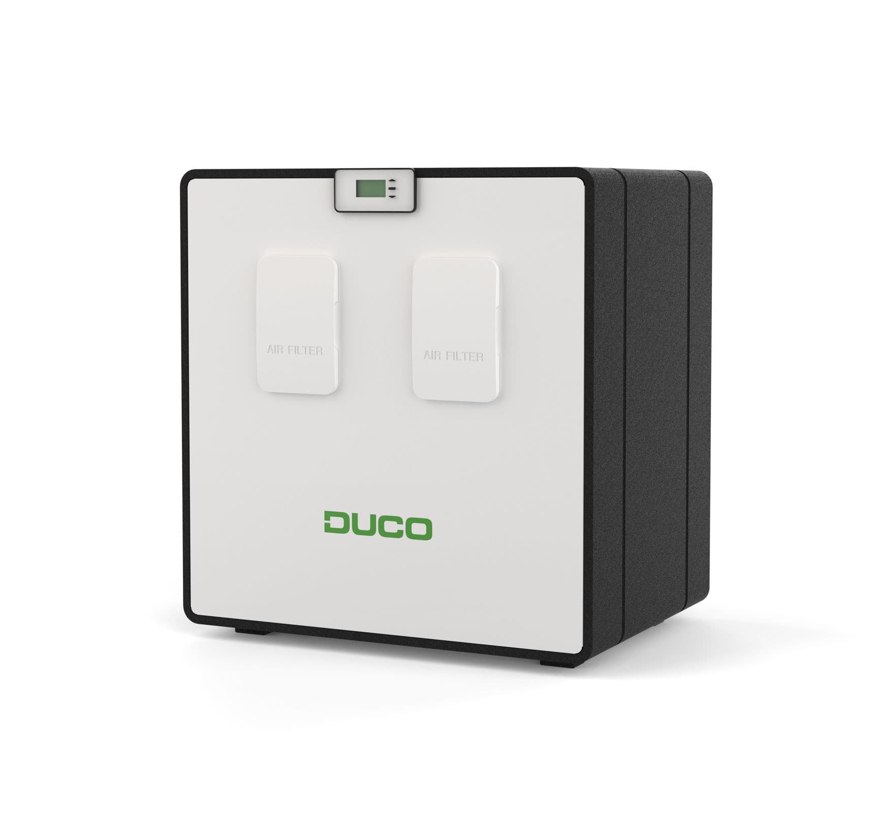
DucoBox Energy
Monitors and controls DucoBox Energy ventilation systems via Modbus TCP
Template for the DucoBox Energy family of ventilation systems using Modbus TCP (API v2.5). Reads ventilation status, air quality (CO2, RH), temperatures, and flow rates. Allows control of ventilation positions, target temperatures, and mode timing.
- Protocol
- Modbus TCP
- Connection
- Ethernet, Modbus TCP
- Registers
- 40, read and write
- Brand
- Duco
- Key readings
- Ventilation status and position (box and valves) · Indoor air quality CO2 (% and PPM) · Indoor air relative humidity · Supply, extract, and outdoor temperatures · Flow rate vs. target level · Remaining time current ventilation mode
- Available commands
- Ventilation position (box and valves) · Target supply temperature zone 4 · Indoor air quality RH setpoint · Remaining time ventilation mode
- Compatible models
- DucoBox Energy Comfort · DucoBox Energy Comfort Plus · DucoBox Energy Premium · DucoBox Energy Sky
- Last updated
Registers (40)
40 read, 9 write
| Name | Unit | Access | Address (Hidden until you enter your email) | Function (hidden) | Type (hidden) |
|---|---|---|---|---|---|
| Ventilation Status box (node 1) | Read | ||||
| Remaining time current ventilation mode box (node 1) | s | Read and write | |||
| Flow rate vs. Target level box (node 1) | % | Read and write | |||
| Ventilation position Valve (node 2) | Read and write | ||||
| Ventilation position box (node 1) | Read and write | ||||
| Ventilation position Valve (node 3) | Read and write | ||||
| Ventilation position Valve (node 5) | Read and write | ||||
| Remaining time current ventilation mode Valve (node 2) | s | Read | |||
| Remaining time current ventilation mode Valve (node 4) | s | Read | |||
| Remaining time current ventilation mode Valve (node 3) | s | Read | |||
| Indoor Air quality CO2 Roomsensor (node 5) | % | Read | |||
| Indoor Air quality CO2 Roomsensor PPM (node 7) | PPM | Read | |||
| Indoor Air quality RH Box (node 1) | % | Read and write | |||
| Indoor Air RH Box (node 1) | % | Read | |||
| Flow rate vs. Target level Valve (node 2) | % | Read | |||
| Indoor Air quality CO2 Roomsensor (node 6) | % | Read | |||
| Indoor Air quality CO2 Roomsensor (node 7) | % | Read | |||
| Indoor Air quality CO2 Roomsensor PPM (node 8) | PPM | Read | |||
| Indoor Air quality CO2 Roomsensor (node 8) | % | Read | |||
| Indoor Air quality CO2 Roomsensor PPM (node 6) | PPM | Read | |||
| Indoor Air quality CO2 Roomsensor PPM (node 5) | PPM | Read | |||
| Flow rate vs. Target level Valve (node 3) | % | Read | |||
| Flow rate vs. Target level Valve (node 4) | % | Read | |||
| Temprature ODA (Outdoor supply) | °C | Read | |||
| Target supply temperature zone 1 | °C | Read | |||
| Target supply temperature zone 2 | °C | Read | |||
| Target supply temperature zone 3 | °C | Read | |||
| Temprature SUP (Building supply) | °C | Read | |||
| Temprature ETA (Building Etract) | °C | Read | |||
| Temprature EHA (Outdoor Etract) | °C | Read | |||
| Amount of sending commands left for the day | count | Read | |||
| Target supply temperature zone 4 | °C | Read and write | |||
| Outdoor temprature Sensor | °C | Read | |||
| Flow rate vs. Target level Valve (node 5) | % | Read | |||
| Indoor Air quality CO2 Roomsensor (node 9) | % | Read | |||
| Indoor Air quality CO2 Roomsensor (node 10) | % | Read | |||
| Indoor Air quality CO2 Roomsensor PPM (node 10) | PPM | Read | |||
| Indoor Air quality CO2 Roomsensor PPM (node 9) | PPM | Read | |||
| Remaining time current ventilation mode Valve (node 5) | s | Read | |||
| Ventilation position Valve (node 4) | Read and write |
Loading registers…
Send your device list
If a device is not in the library yet, we build the template for free as soon as we have the register data.
Use cases
- Monitor indoor CO2 and relative humidity levels on a live dashboard to verify ventilation performance for your customer.
- Create an alert when supply air temperature deviates from the target setpoint for more than 15 minutes.
- Remotely adjust ventilation positions and mode timing without an on-site visit.
- Track daily flow rates versus target levels to identify underperforming zones or blocked valves.
- Log outdoor and extract temperatures over time to optimize energy recovery efficiency.
- Set up a notification when the daily write command limit drops below a safe threshold.
Installation
Ensure the DucoBox Energy unit is equipped with a connectivity board that enables Modbus TCP communication.
Connect the DucoBox to the same local network as your ModbusCloud Gateway using an Ethernet cable.
Verify that the DucoBox is running firmware compatible with API v2.5 and note the unit's IP address and Modbus TCP port.
In the ModbusCloud platform, import the DucoBox Energy template and assign it to the correct gateway.
Configure the IP address and port of the DucoBox in the gateway's Modbus TCP connection settings.
Confirm that readings such as ventilation status, CO2 values, and temperatures appear correctly on the ModbusCloud dashboard.
Things to watch for
Why do some registers return unexpected values when read and written simultaneously?
Registers at addresses like 100, 102, 103, 104, and 105 are holding registers used for both reading and writing. Always read after a write operation to confirm the value was accepted. Avoid simultaneous read and write polling on these addresses.
My write commands are being rejected during the day. What is going on?
The DucoBox Energy firmware enforces a daily limit on write commands. Check register address 31 to see how many writes remain. Reduce the frequency of write operations in your automations to stay within the allowed budget.
I cannot establish a Modbus TCP connection to the DucoBox. What should I check?
Confirm that the connectivity board is installed and powered. Verify the DucoBox IP address and that it is reachable from the gateway's network. Check that no firewall rules are blocking the Modbus TCP port (default is typically 502).
Which DucoBox models are supported by this template?
This template supports the DucoBox Energy Comfort, Comfort Plus, Premium, and Sky models, provided they are equipped with a connectivity board and run firmware supporting API v2.5.
More Duco templates
Want to see how it works?
