








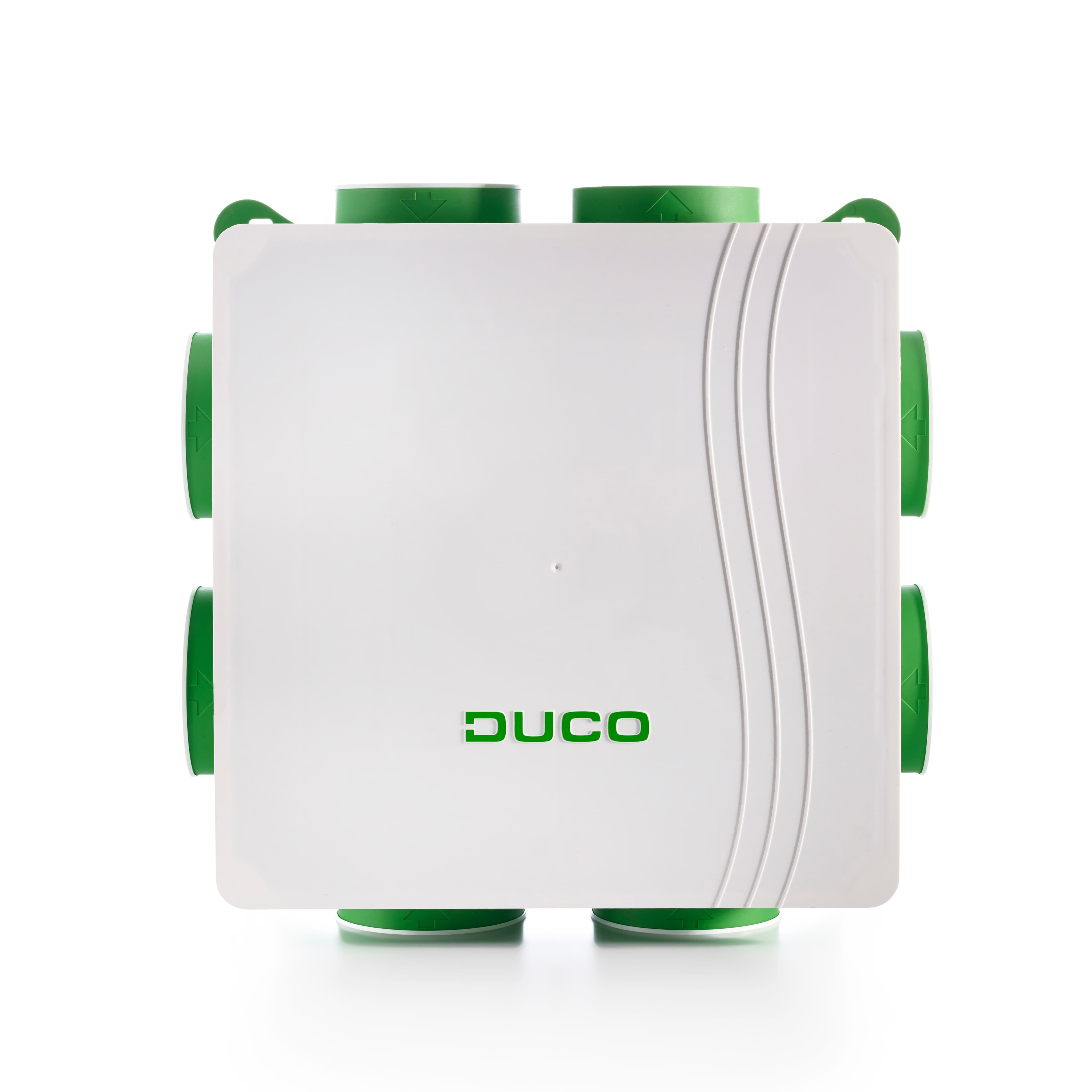
DucoBox Silent Connect
Monitors and controls ventilation parameters on DucoBox Silent Connect units.
Template for the DucoBox Silent Connect ventilation unit via Modbus TCP (API v2.5). Reads indoor air quality sensors (RH, CO2), ventilation status, flow rate and remaining time. Also allows writing the ventilation position setpoint.
- Protocol
- Modbus TCP
- Connection
- Ethernet, Modbus TCP
- Registers
- 6, read and write
- Brand
- Duco
- Key readings
- Indoor Air Quality RH · Indoor Air Quality CO2 · Remaining Time Current Ventilation Mode · Flow Rate vs Target Level · Ventilation Status · Ventilation Position
- Available commands
- Ventilation Position
- Compatible models
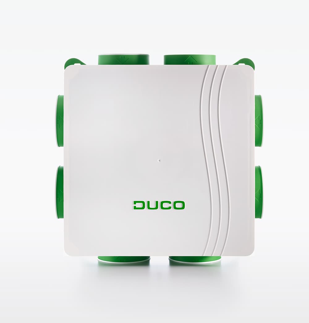
- DucoBox Silent Connect
- Last updated
Registers (6)
6 read, 1 write
| Name | Unit | Access | Address (Hidden until you enter your email) | Function (hidden) | Type (hidden) |
|---|---|---|---|---|---|
| Indoor Air quality RH box (node 1) | % | Read | |||
| Indoor Air quality CO2 box (node 1) | ppm | Read | |||
| Remaining time current ventilation mode box (node 1) | s | Read | |||
| Flow rate VS. Target level box (node 1) | % | Read | |||
| Ventilation status box (node 1) | Read | ||||
| Ventilation position box (node 1) | Read and write |
Loading registers…
Send your device list
If a device is not in the library yet, we build the template for free as soon as we have the register data.
Use cases
- Monitor indoor CO2 and relative humidity levels on a live dashboard to verify ventilation performance.
- Adjust the ventilation position setpoint remotely when occupancy or usage patterns change.
- Create an alert when CO2 concentration exceeds a threshold for more than 15 minutes.
- Log flow rate and ventilation status over time to identify under-ventilation in residential projects.
- Verify remaining time in the current ventilation mode after a manual override by the occupant.
- Compare actual flow rate against the target level to detect ductwork issues or filter blockage.
Installation
Ensure the DucoBox Silent Connect is equipped with a connectivity board that supports Modbus TCP.
Connect the ModbusCloud Gateway to the same local network as the DucoBox connectivity board.
Configure the IP address of the DucoBox connectivity board in the ModbusCloud gateway settings and set the correct Modbus TCP port.
Import the DucoBox Silent Connect template (API v2.5) in the ModbusCloud platform and assign it to the gateway.
Verify that readings such as CO2, RH, ventilation status and flow rate appear on the dashboard after the first polling cycle.
Test the ventilation position write register by sending a setpoint change from the dashboard and confirming the unit responds.
Things to watch for
The gateway cannot connect to the DucoBox over Modbus TCP. What should I check?
Verify that the connectivity board is installed and powered. Confirm the IP address and TCP port are correct in the gateway configuration. Make sure both devices are on the same network or VLAN.
Do I need a specific firmware version on the DucoBox Silent Connect?
This template is based on API v2.5. Ensure your DucoBox connectivity board firmware supports API v2.5 or later. Refer to the Duco Modbus documentation for firmware compatibility details.
The CO2 and RH readings show zero or unexpected values. Why?
Check whether the corresponding sensors are physically connected to the DucoBox. If no CO2 sensor is installed, the register will return a default or zero value. Also verify that the sensors are configured in the DucoBox setup menu.
Can I control multiple DucoBox units from one gateway?
Yes. Add a separate device entry in ModbusCloud for each DucoBox, each with its own IP address. Apply the same template to each device. The gateway will poll them independently.
More Duco templates
Want to see how it works?
