
Eliwell EWCM 9100 EO
Compressor rack controller for suction pressure, condenser fans and rack alarms.
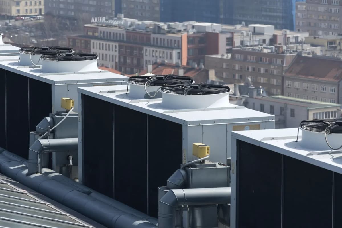
The Eliwell EWCM 9100 EO is a controller that runs the compressors and condenser fans of a refrigeration compressor rack in supermarkets and cold stores. This Modbus RTU template reads suction and discharge pressure, setpoints, power, compressor and fan states and alarms, and lets you switch the rack, reset alarms and change setpoints from ModbusCloud.
- Protocol
- Modbus RTU
- Connection
- RS485, 9600 baud
- Registers
- 890, read and write
- Brand
- Eliwell
- Key readings
- Suction pressure · Discharge pressure · Suction setpoint · Power per circuit · Compressor status · Fan status · Running hours · Alarms
- Available commands
- Rack on/off · Alarm mute and reset · Suction setpoint · Discharge setpoint · Compressor selection · Energy saving
- Compatible models
- EWCM 9100 EO · EWCM 8900 EO · EWCM 9900 EO · EWCM 9100 EO HFO
- Last updated
Registers (890)
839 read, 553 write
| Name | Unit | Access | Address (Hidden until you enter your email) | Function (hidden) | Type (hidden) |
|---|---|---|---|---|---|
| Suction Probe Circuit 1 (°C) | °C | Read | 4752 | FC03 | int16 |
| Suction Probe Circuit 1 (°F) | °F | Read | 4753 | FC03 | int16 |
| Suction Probe Circuit 1 (bar) | bar | Read | 4754 | FC03 | int16 |
| Suction Probe Circuit 1 (psi) | psi | Read | 4755 | FC03 | int16 |
| Suction Setpoint Circuit 1 (°C) | °C | Read | 4778 | FC03 | int16 |
| Suction Setpoint Circuit 1 (°F) | °F | Read | |||
| Suction Setpoint Circuit 1 (bar) | bar | Read | |||
| Suction Setpoint Circuit 1 (psi) | psi | Read | |||
| Suction Setpoint Offset Circuit 1 | Read | ||||
| Suction Probe Circuit 2 (°C) | °C | Read | |||
| Suction Probe Circuit 2 (°F) | °F | Read | |||
| Suction Probe Circuit 2 (bar) | bar | Read | |||
| Suction Probe Circuit 2 (psi) | psi | Read | |||
| Suction Setpoint Circuit 2 (°C) | °C | Read | |||
| Suction Setpoint Circuit 2 (°F) | °F | Read | |||
| Suction Setpoint Circuit 2 (bar) | bar | Read | |||
| Suction Setpoint Circuit 2 (psi) | psi | Read | |||
| Suction Setpoint Offset Circuit 2 | Read | ||||
| Discharge Probe (°C) | °C | Read | |||
| Discharge Probe (°F) | °F | Read | |||
| Discharge Probe (bar) | bar | Read | |||
| Discharge Probe (psi) | psi | Read | |||
| Discharge Setpoint (°C) | °C | Read | |||
| Discharge Setpoint (°F) | °F | Read | |||
| Discharge Setpoint (bar) | bar | Read | |||
| Discharge Setpoint (psi) | psi | Read | |||
| Internal Ambient Probe (°C) | °C | Read | |||
| Internal Ambient Probe (°F) | °F | Read | |||
| External Ambient Probe (°C) | °C | Read | |||
| External Ambient Probe (°F) | °F | Read | |||
| Sub-cooling Temperature Probe (°C) | °C | Read | |||
| Sub-cooling Temperature Probe (°F) | °F | Read | |||
| Heat Recovery Water Probe (°C) | °C | Read | |||
| Heat Recovery Water Probe (°F) | °F | Read | |||
| Configurable Regulator Probe (°C) | °C | Read | |||
| Configurable Regulator Probe (°F) | °F | Read | |||
| Configurable Regulator Probe and Configurable Alarm (°C) | °C | Read | |||
| Configurable Regulator Probe and Configurable Alarm (°F) | °F | Read | |||
| Configurable Alarm Probe (°C) | °C | Read | |||
| Configurable Alarm Probe (°F) | °F | Read | |||
| Power Delivered by Circuit 1 | % | Read | |||
| Power Delivered by Circuit 2 | % | Read | |||
| Selection Compressor 1 | Read | ||||
| Compressor 1 | Read | ||||
| Compressor 1 Step 1 Relay | Read | ||||
| Compressor 1 Step 2 Relay | Read | ||||
| Compressor 1 Step 3 Relay | Read | ||||
| Compressor 1 Step 4 Relay | Read | ||||
| Compressor 1 Step 5 Relay | Read | ||||
| Power Generated by Compressor 1 | % | Read | |||
| Operation Hours Compressor 1 | Read | ||||
| Selection Compressor 2 | Read | ||||
| Compressor 2 | Read | ||||
| Compressor 2 Step 1 Relay | Read | ||||
| Compressor 2 Step 2 Relay | Read | ||||
| Compressor 2 Step 3 Relay | Read | ||||
| Compressor 2 Step 4 Relay | Read | ||||
| Compressor 2 Step 5 Relay | Read | ||||
| Power Generated by Compressor 2 | % | Read | |||
| Operation Hours Compressor 2 | Read | ||||
| Selection Compressor 3 | Read | ||||
| Compressor 3 | Read | ||||
| Compressor 3 Step 1 Relay | Read | ||||
| Compressor 3 Step 2 Relay | Read | ||||
| Compressor 3 Step 3 Relay | Read | ||||
| Compressor 3 Step 4 Relay | Read | ||||
| Compressor 3 Step 5 Relay | Read | ||||
| Power Generated by Compressor 3 | % | Read | |||
| Operation Hours Compressor 3 | Read | ||||
| Selection Compressor 4 | Read | ||||
| Compressor 4 | Read | ||||
| Compressor 4 Step 1 Relay | Read | ||||
| Compressor 4 Step 2 Relay | Read | ||||
| Compressor 4 Step 3 Relay | Read | ||||
| Compressor 4 Step 4 Relay | Read | ||||
| Compressor 4 Step 5 Relay | Read | ||||
| Power Generated by Compressor 4 | % | Read | |||
| Operation Hours Compressor 4 | Read | ||||
| Selection Compressor 5 | Read | ||||
| Compressor 5 | Read | ||||
| Compressor 5 Step 1 Relay | Read | ||||
| Compressor 5 Step 2 Relay | Read | ||||
| Compressor 5 Step 3 Relay | Read | ||||
| Compressor 5 Step 4 Relay | Read | ||||
| Compressor 5 Step 5 Relay | Read | ||||
| Power Generated by Compressor 5 | % | Read | |||
| Operation Hours Compressor 5 | Read | ||||
| Selection Compressor 6 | Read | ||||
| Compressor 6 | Read | ||||
| Compressor 6 Step 1 Relay | Read | ||||
| Compressor 6 Step 2 Relay | Read | ||||
| Compressor 6 Step 3 Relay | Read | ||||
| Compressor 6 Step 4 Relay | Read | ||||
| Compressor 6 Step 5 Relay | Read | ||||
| Power Generated by Compressor 6 | % | Read | |||
| Operation Hours Compressor 6 | Read | ||||
| Selection Compressor 7 | Read | ||||
| Compressor 7 | Read | ||||
| Compressor 7 Step 1 Relay | Read | ||||
| Compressor 7 Step 2 Relay | Read | ||||
| Compressor 7 Step 3 Relay | Read | ||||
| Compressor 7 Step 4 Relay | Read | ||||
| Compressor 7 Step 5 Relay | Read | ||||
| Power Generated by Compressor 7 | % | Read | |||
| Operation Hours Compressor 7 | Read | ||||
| Selection Compressor 8 | Read | ||||
| Compressor 8 | Read | ||||
| Compressor 8 Step 1 Relay | Read | ||||
| Compressor 8 Step 2 Relay | Read | ||||
| Compressor 8 Step 3 Relay | Read | ||||
| Compressor 8 Step 4 Relay | Read | ||||
| Compressor 8 Step 5 Relay | Read | ||||
| Power Generated by Compressor 8 | % | Read | |||
| Operation Hours Compressor 8 | Read | ||||
| Selection Compressor 9 | Read | ||||
| Compressor 9 | Read | ||||
| Compressor 9 Step 1 Relay | Read | ||||
| Compressor 9 Step 2 Relay | Read | ||||
| Compressor 9 Step 3 Relay | Read | ||||
| Compressor 9 Step 4 Relay | Read | ||||
| Compressor 9 Step 5 Relay | Read | ||||
| Power Generated by Compressor 9 | % | Read | |||
| Operation Hours Compressor 9 | Read | ||||
| Selection Compressor 10 | Read | ||||
| Compressor 10 | Read | ||||
| Compressor 10 Step 1 Relay | Read | ||||
| Compressor 10 Step 2 Relay | Read | ||||
| Compressor 10 Step 3 Relay | Read | ||||
| Compressor 10 Step 4 Relay | Read | ||||
| Compressor 10 Step 5 Relay | Read | ||||
| Power Generated by Compressor 10 | % | Read | |||
| Operation Hours Compressor 10 | Read | ||||
| Selection Compressor 11 | Read | ||||
| Compressor 11 | Read | ||||
| Compressor 11 Step 1 Relay | Read | ||||
| Compressor 11 Step 2 Relay | Read | ||||
| Compressor 11 Step 3 Relay | Read | ||||
| Compressor 11 Step 4 Relay | Read | ||||
| Compressor 11 Step 5 Relay | Read | ||||
| Power Generated by Compressor 11 | % | Read | |||
| Operation Hours Compressor 11 | Read | ||||
| Selection Compressor 12 | Read | ||||
| Compressor 12 | Read | ||||
| Compressor 12 Step 1 Relay | Read | ||||
| Compressor 12 Step 2 Relay | Read | ||||
| Compressor 12 Step 3 Relay | Read | ||||
| Compressor 12 Step 4 Relay | Read | ||||
| Compressor 12 Step 5 Relay | Read | ||||
| Power Generated by Compressor 12 | % | Read | |||
| Operation Hours Compressor 12 | Read | ||||
| Selection Compressor Inverter Circuit 1 | Read | ||||
| State of Compressor on Inverter, Suction 1 | Read | ||||
| Power of Compressor on Inverter, Suction 1 | % | Read | |||
| Compressor Inverter Running Hours Circuit 1 | Read | ||||
| Selection Compressor Inverter Circuit 2 | Read | ||||
| State of Compressor on Inverter, Suction 2 | Read | ||||
| Power of Compressor on Inverter, Suction 2 | % | Read | |||
| Compressor Inverter Running Hours Circuit 2 | Read | ||||
| Fan State 1 | Read | ||||
| Fan Running Time 1 | Read | ||||
| Fan State 2 | Read | ||||
| Fan Running Time 2 | Read | ||||
| Fan State 3 | Read | ||||
| Fan Running Time 3 | Read | ||||
| Fan State 4 | Read | ||||
| Fan Running Time 4 | Read | ||||
| Fan State 5 | Read | ||||
| Fan Running Time 5 | Read | ||||
| Fan State 6 | Read | ||||
| Fan Running Time 6 | Read | ||||
| Fan State 7 | Read | ||||
| Fan Running Time 7 | Read | ||||
| Fan State 8 | Read | ||||
| Fan Running Time 8 | Read | ||||
| Fan on Inverter | Read | ||||
| Power Generated by Fans on Inverter | % | Read | |||
| Fan Inverter Running Hours | Read | ||||
| Configurable Regulator Relay Step 1 | Read | ||||
| Power Delivered by Configurable Regulator Step 1 | % | Read | |||
| Configurable Regulator Relay Step 2 | Read | ||||
| Valve Opening Percentage | % | Read | |||
| Valve Overheating Temperature | °C | Read | |||
| Valve Discharge Pressure | psi | Read | |||
| Valve Status Bits | Read | ||||
| Economy Function, Suction 1 | Read | ||||
| Economy Function, Suction 2 | Read | ||||
| Economy, Discharge | Read | ||||
| AUX Output 1 | Read | ||||
| AUX Output 2 | Read | ||||
| AUX Output 3 | Read | ||||
| AUX Output 4 | Read | ||||
| Glycol Defrost on | Read | ||||
| Energy Saving Function | Read | ||||
| Alarm Mute | Read | ||||
| Heat Recovery | Read | ||||
| Liquid Return Control Function, Suction 1 | Read | ||||
| Liquid Return Control Function, Suction 2 | Read | ||||
| Hot Gas Defrost Circuit 1 on | Read | ||||
| Hot Gas Defrost Circuit 2 on | Read | ||||
| Stand-by | Read | ||||
| Alarm | Read | ||||
| General Alarm | Read | ||||
| High Pressure Switch, Suction 1 | Read | ||||
| Low Pressure Switch, Suction 1 | Read | ||||
| High Pressure Switch, Suction 2 | Read | ||||
| Low Pressure Switch, Suction 2 | Read | ||||
| High Pressure, Suction 1 | Read | ||||
| Low Pressure, Suction 1 | Read | ||||
| High Pressure, Suction 2 | Read | ||||
| Low Pressure, Suction 2 | Read | ||||
| Refrigerant Level Low | Read | ||||
| Refrigerant Leakage | Read | ||||
| Low Pressure Switch, Discharge | Read | ||||
| High Pressure Switch, Discharge | Read | ||||
| High Pressure, Discharge | Read | ||||
| Low Pressure, Discharge | Read | ||||
| Oil Level Low, Suction 1 | Read | ||||
| Oil Level Low, Suction 2 | Read | ||||
| Block Compressor 1 | Read | ||||
| Compressor 1 Differential Pressure Switch | Read | ||||
| High Pressure Compressor 1 | Read | ||||
| Low Pressure Compressor 1 | Read | ||||
| Thermal Switch Compressor 1 | Read | ||||
| Compressor 1 Operating Hours Exceeded Warning | Read | ||||
| Block Compressor 2 | Read | ||||
| Compressor 2 Differential Pressure Switch | Read | ||||
| High Pressure Compressor 2 | Read | ||||
| Low Pressure Compressor 2 | Read | ||||
| Thermal Switch Compressor 2 | Read | ||||
| Compressor 2 Operating Hours Exceeded Warning | Read | ||||
| Block Compressor 3 | Read | ||||
| Compressor 3 Differential Pressure Switch | Read | ||||
| High Pressure Compressor 3 | Read | ||||
| Low Pressure Compressor 3 | Read | ||||
| Thermal Switch Compressor 3 | Read | ||||
| Compressor 3 Operating Hours Exceeded Warning | Read | ||||
| Block Compressor 4 | Read | ||||
| Compressor 4 Differential Pressure Switch | Read | ||||
| High Pressure Compressor 4 | Read | ||||
| Low Pressure Compressor 4 | Read | ||||
| Thermal Switch Compressor 4 | Read | ||||
| Compressor 4 Operating Hours Exceeded Warning | Read | ||||
| Block Compressor 5 | Read | ||||
| Compressor 5 Differential Pressure Switch | Read | ||||
| High Pressure Compressor 5 | Read | ||||
| Low Pressure Compressor 5 | Read | ||||
| Thermal Switch Compressor 5 | Read | ||||
| Compressor 5 Operating Hours Exceeded Warning | Read | ||||
| Block Compressor 6 | Read | ||||
| Compressor 6 Differential Pressure Switch | Read | ||||
| High Pressure Compressor 6 | Read | ||||
| Low Pressure Compressor 6 | Read | ||||
| Thermal Switch Compressor 6 | Read | ||||
| Compressor 6 Operating Hours Exceeded Warning | Read | ||||
| Block Compressor 7 | Read | ||||
| Compressor 7 Differential Pressure Switch | Read | ||||
| High Pressure Compressor 7 | Read | ||||
| Low Pressure Compressor 7 | Read | ||||
| Thermal Switch Compressor 7 | Read | ||||
| Compressor 7 Operating Hours Exceeded Warning | Read | ||||
| Block Compressor 8 | Read | ||||
| Compressor 8 Differential Pressure Switch | Read | ||||
| High Pressure Compressor 8 | Read | ||||
| Low Pressure Compressor 8 | Read | ||||
| Thermal Switch Compressor 8 | Read | ||||
| Compressor 8 Operating Hours Exceeded Warning | Read | ||||
| Block Compressor 9 | Read | ||||
| Compressor 9 Differential Pressure Switch | Read | ||||
| High Pressure Compressor 9 | Read | ||||
| Low Pressure Compressor 9 | Read | ||||
| Thermal Switch Compressor 9 | Read | ||||
| Compressor 9 Operating Hours Exceeded Warning | Read | ||||
| Block Compressor 10 | Read | ||||
| Compressor 10 Differential Pressure Switch | Read | ||||
| High Pressure Compressor 10 | Read | ||||
| Low Pressure Compressor 10 | Read | ||||
| Thermal Switch Compressor 10 | Read | ||||
| Compressor 10 Operating Hours Exceeded Warning | Read | ||||
| Block Compressor 11 | Read | ||||
| Compressor 11 Differential Pressure Switch | Read | ||||
| High Pressure Compressor 11 | Read | ||||
| Low Pressure Compressor 11 | Read | ||||
| Thermal Switch Compressor 11 | Read | ||||
| Compressor 11 Operating Hours Exceeded Warning | Read | ||||
| Block Compressor 12 | Read | ||||
| Compressor 12 Differential Pressure Switch | Read | ||||
| High Pressure Compressor 12 | Read | ||||
| Low Pressure Compressor 12 | Read | ||||
| Thermal Switch Compressor 12 | Read | ||||
| Compressor 12 Operating Hours Exceeded Warning | Read | ||||
| Stop Compressor on Inverter, Suction 1 | Read | ||||
| Inverter Error, Suction 1 | Read | ||||
| Running Time of Compressor on Inverter Exceeded, Suction 1 | Read | ||||
| Stop Compressor on Inverter, Suction 2 | Read | ||||
| Inverter Error, Suction 2 | Read | ||||
| Running Time of Compressor on Inverter Exceeded, Suction 2 | Read | ||||
| Thermal Protection Fan 1 | Read | ||||
| Fan Exceeded Running Time 1 | Read | ||||
| Thermal Protection Fan 2 | Read | ||||
| Fan Exceeded Running Time 2 | Read | ||||
| Thermal Protection Fan 3 | Read | ||||
| Fan Exceeded Running Time 3 | Read | ||||
| Thermal Protection Fan 4 | Read | ||||
| Fan Exceeded Running Time 4 | Read | ||||
| Thermal Protection Fan 5 | Read | ||||
| Fan Exceeded Running Time 5 | Read | ||||
| Thermal Protection Fan 6 | Read | ||||
| Fan Exceeded Running Time 6 | Read | ||||
| Thermal Protection Fan 7 | Read | ||||
| Fan Exceeded Running Time 7 | Read | ||||
| Thermal Protection Fan 8 | Read | ||||
| Fan Exceeded Running Time 8 | Read | ||||
| Inverter Error, Discharge | Read | ||||
| Thermal Switch for Fan on Inverter | Read | ||||
| Running Time of Fan on Inverter Exceeded | Read | ||||
| High Pressure Alarm Prevention Timeout, Discharge | Read | ||||
| Suction Probe Error, Suction 1 | Read | ||||
| Suction Probe Error, Suction 2 | Read | ||||
| Discharge Probe Error | Read | ||||
| Internal Temperature Probe Error | Read | ||||
| External Temperature Probe Error | Read | ||||
| Heat Recovery Temperature Probe Error | Read | ||||
| Sub-cooling Temperature Probe Error | Read | ||||
| Configurable Regulator Probe Error | Read | ||||
| Configurable Alarm Regulator Probe Error | Read | ||||
| Error Opening Recordings File | Read | ||||
| Error Writing Recordings File | Read | ||||
| Error Closing Recordings File | Read | ||||
| Recordings Memory Full Error | Read | ||||
| Configuration Error Alarm | Read | ||||
| External Eeprom CRC Error Alarm | Read | ||||
| External Eeprom User Parameters CRC Error Alarm | Read | ||||
| RTA Battery Low Alarm | Read | ||||
| RTC Communication Error Alarm | Read | ||||
| Alarm RTC Register Value not Consistent | Read | ||||
| Configurable Regulator Alarm | Read | ||||
| Valve 1 No-link Alarm | Read | ||||
| Instrument On/Off | Write | ||||
| Alarm Mute Command | Write | ||||
| Reset Alarm History | Write | ||||
| Alarm Manual Reset | Write | ||||
| Enable/disable Economy, Suction 1 | Write | ||||
| Enable/disable Economy, Suction 2 | Write | ||||
| Enable/disable Economy, Discharge | Write | ||||
| Enable/disable Energy Saving | Write | ||||
| On/Off Auxiliary 1 | Write | ||||
| On/Off Auxiliary 2 | Write | ||||
| On/Off Auxiliary 3 | Write | ||||
| Reset Compressor Running Time 1 | Write | ||||
| Selection Compressor 1 Command | Write | ||||
| Reset Compressor Running Time 2 | Write | ||||
| Selection Compressor 2 Command | Write | ||||
| Reset Compressor Running Time 3 | Write | ||||
| Selection Compressor 3 Command | Write | ||||
| Reset Compressor Running Time 4 | Write | ||||
| Selection Compressor 4 Command | Write | ||||
| Reset Compressor Running Time 5 | Write | ||||
| Selection Compressor 5 Command | Write | ||||
| Reset Compressor Running Time 6 | Write | ||||
| Selection Compressor 6 Command | Write | ||||
| Reset Compressor Running Time 7 | Write | ||||
| Selection Compressor 7 Command | Write | ||||
| Reset Compressor Running Time 8 | Write | ||||
| Selection Compressor 8 Command | Write | ||||
| Reset Compressor Running Time 9 | Write | ||||
| Selection Compressor 9 Command | Write | ||||
| Reset Compressor Running Time 10 | Write | ||||
| Selection Compressor 10 Command | Write | ||||
| Reset Compressor Running Time 11 | Write | ||||
| Selection Compressor 11 Command | Write | ||||
| Reset Compressor Running Time 12 | Write | ||||
| Selection Compressor 12 Command | Write | ||||
| Reset Running Time of Compressor on Inverter, Suction 1 | Write | ||||
| Selection Compressor on Inverter, Suction 1 | Write | ||||
| Reset Running Time of Compressor on Inverter, Suction 2 | Write | ||||
| Selection Compressor on Inverter, Suction 2 | Write | ||||
| Reset Fan Running Hours 1 | Write | ||||
| Reset Fan Running Hours 2 | Write | ||||
| Reset Fan Running Hours 3 | Write | ||||
| Reset Fan Running Hours 4 | Write | ||||
| Reset Fan Running Hours 5 | Write | ||||
| Reset Fan Running Hours 6 | Write | ||||
| Reset Fan Running Hours 7 | Write | ||||
| Reset Fan Running Hours 8 | Write | ||||
| Reset Running Time of the Fan on Inverter, Discharge | Write | ||||
| Configuration Mode Request | Write | ||||
| Automatic Update of Associated Parameters | Write | ||||
| Refresh Watchdog Floating Suction Setpoint | Write | ||||
| Password 1 | Read and write | ||||
| TAB | Read and write | ||||
| Enable RTC | Read and write | ||||
| Refrigerant Type | Read and write | ||||
| PB 1/2 Probe Type | Read and write | ||||
| PB 3/4 Probe Type | Read and write | ||||
| PB 5/6 Probe Type | Read and write | ||||
| PB 7/8 Probe Type | Read and write | ||||
| PB1 High Precision | Read and write | ||||
| PB2 High Precision | Read and write | ||||
| Select V1 or I1 | Read and write | ||||
| Select V2 or I2 | Read and write | ||||
| Select V3 or I3 | Read and write | ||||
| PB1 Calibration (bar, x0.01) | bar | Read and write | |||
| PB1 Calibration (psi, x0.1) | psi | Read and write | |||
| PB1 Calibration (bar, x0.1) | bar | Read and write | |||
| PB1 Calibration (psi, x1) | psi | Read and write | |||
| PB1 Calibration (°C) | °C | Read and write | |||
| PB1 Calibration (°F) | °F | Read and write | |||
| PB2 Calibration (bar, x0.01) | bar | Read and write | |||
| PB2 Calibration (psi, x0.1) | psi | Read and write | |||
| PB2 Calibration (bar, x0.1) | bar | Read and write | |||
| PB2 Calibration (psi, x1) | psi | Read and write | |||
| PB2 Calibration (°C) | °C | Read and write | |||
| PB2 Calibration (°F) | °F | Read and write | |||
| PB3 Calibration (bar) | bar | Read and write | |||
| PB3 Calibration (psi) | psi | Read and write | |||
| PB3 Calibration (°C) | °C | Read and write | |||
| PB3 Calibration (°F) | °F | Read and write | |||
| PB5 Calibration (°C) | °C | Read and write | |||
| PB5 Calibration (°F) | °F | Read and write | |||
| PB6 Calibration (°C) | °C | Read and write | |||
| PB6 Calibration (°F) | °F | Read and write | |||
| PB7 Calibration (°C) | °C | Read and write | |||
| PB7 Calibration (°F) | °F | Read and write | |||
| PB8 Calibration (°C) | °C | Read and write | |||
| PB8 Calibration (°F) | °F | Read and write | |||
| Lower Threshold PB1 (bar, x0.01) | bar | Read and write | |||
| Lower Threshold PB1 (psi, x0.1) | psi | Read and write | |||
| Lower Threshold PB1 (bar, x0.1) | bar | Read and write | |||
| Lower Threshold PB1 (psi, x1) | psi | Read and write | |||
| Upper Threshold PB1 (bar, x0.01) | bar | Read and write | |||
| Upper Threshold PB1 (psi, x0.1) | psi | Read and write | |||
| Upper Threshold PB1 (bar, x0.1) | bar | Read and write | |||
| Upper Threshold PB1 (psi, x1) | psi | Read and write | |||
| Lower Threshold PB2 (bar, x0.01) | bar | Read and write | |||
| Lower Threshold PB2 (psi, x0.1) | psi | Read and write | |||
| Lower Threshold PB2 (bar, x0.1) | bar | Read and write | |||
| Lower Threshold PB2 (psi, x1) | psi | Read and write | |||
| Upper Threshold PB2 (bar, x0.01) | bar | Read and write | |||
| Upper Threshold PB2 (psi, x0.1) | psi | Read and write | |||
| Upper Threshold PB2 (bar, x0.1) | bar | Read and write | |||
| Upper Threshold PB2 (psi, x1) | psi | Read and write | |||
| Lower Threshold PB3 (bar) | bar | Read and write | |||
| Lower Threshold PB3 (psi) | psi | Read and write | |||
| Upper Threshold PB3 (bar) | bar | Read and write | |||
| Upper Threshold PB3 (psi) | psi | Read and write | |||
| Lower Threshold PB4 (bar) | bar | Read and write | |||
| Lower Threshold PB4 (psi) | psi | Read and write | |||
| Upper Threshold PB4 (bar) | bar | Read and write | |||
| Upper Threshold PB4 (psi) | psi | Read and write | |||
| Family Address | Read and write | ||||
| Controller Address | Read and write | ||||
| Protocol Selection RS485 | Read and write | ||||
| Baud Rate RS485 | Read and write | ||||
| Parity Bit RS485 | Read and write | ||||
| Protocol Selection EXP | Read and write | ||||
| Baud Rate EXP | Read and write | ||||
| Parity Bit EXP | Read and write | ||||
| Data Bit EXP | Read and write | ||||
| Enab. ETHERNET | Read and write | ||||
| Type of Plant | Read and write | ||||
| Compressor 1 Power | Read and write | ||||
| Compressor 2 Power | Read and write | ||||
| Compressor 3 Power | Read and write | ||||
| Compressor 4 Power | Read and write | ||||
| Compressor 5 Power | Read and write | ||||
| Compressor 6 Power | Read and write | ||||
| Compressor 7 Power | Read and write | ||||
| Compressor 8 Power | Read and write | ||||
| Compressor 9 Power | Read and write | ||||
| Compressor 10 Power | Read and write | ||||
| Compressor 11 Power | Read and write | ||||
| Compressor 12 Power | Read and write | ||||
| Fan Mode | Read and write | ||||
| Number of Fans | Read and write | ||||
| Circuit 1 Type | Read and write | ||||
| Number of Compressors Circuit 1 | Read and write | ||||
| Circuit 2 Type | Read and write | ||||
| Number of Compressors Circuit 2 | Read and write | ||||
| Enable Cumulative Alarms Digital Output | Read and write | ||||
| Compressor Inverter Enabling Digital Output | Read and write | ||||
| Fan Inverter Enabling Digital Output | Read and write | ||||
| Compressor Inverter 1 and 2 Error Digital Input | Read and write | ||||
| Fan Inverter Error Digital Input | Read and write | ||||
| Enable Generic Alarm Digital Input | Read and write | ||||
| Configurable Regulator Probe Mode | Read and write | ||||
| Configurable Regulator Setpoint Step 1 (°C) | °C | Read and write | |||
| Configurable Regulator Setpoint Step 2 (°C) | °C | Read and write | |||
| Configurable Regulator Delta Step 1 (°C) | °C | Read and write | |||
| Configurable Regulator Delta Step 2 (°C) | °C | Read and write | |||
| Proportional Band Step 1 (°C) | °C | Read and write | |||
| Delta Cut-off Step 1 (°C) | °C | Read and write | |||
| Configurable Regulator Setpoint Step 1 (°F) | °F | Read and write | |||
| Configurable Regulator Setpoint Step 2 (°F) | °F | Read and write | |||
| Configurable Regulator Delta Step 1 (°F) | °F | Read and write | |||
| Configurable Regulator Delta Step 2 (°F) | °F | Read and write | |||
| Proportional Band Step 1 (°F) | °F | Read and write | |||
| Delta Cut-off Step 1 (°F) | °F | Read and write | |||
| Configurable Regulator Delay Step 1 | s | Read and write | |||
| Configurable Regulator Delay Step 2 | s | Read and write | |||
| % Minimum Step 1 | % | Read and write | |||
| % Maximum Step 1 | % | Read and write | |||
| % Saturation Step 1 | % | Read and write | |||
| Configurable Alarm Warning Threshold (°C) | °C | Read and write | |||
| Configurable Alarm Setpoint (°C) | °C | Read and write | |||
| Configurable Alarm Differential (°C) | °C | Read and write | |||
| Configurable Alarm Warning Threshold (°F) | °F | Read and write | |||
| Configurable Alarm Setpoint (°F) | °F | Read and write | |||
| Configurable Alarm Differential (°F) | °F | Read and write | |||
| Configurable Regulator Mode Step 1 | Read and write | ||||
| Configurable Regulator Mode Step 2 | Read and write | ||||
| Enable Warning Configurable Alarm | Read and write | ||||
| Configurable Alarm Mode | Read and write | ||||
| Enable Electronic Valve Driver | Read and write | ||||
| Delay Activation High Temperature Central (MT) at Minimum Power | s | Read and write | |||
| Compressor Delay after MT Central Consent | s | Read and write | |||
| Exit Menu Timeout | s | Read and write | |||
| Min Suction/discharge UM | Read and write | ||||
| Max Suction/discharge UM | Read and write | ||||
| Suction UM | Read and write | ||||
| Discharge UM | Read and write | ||||
| Unlock Keyboard Hotkey | Read and write | ||||
| Language Selection | Read and write | ||||
| Relative Pressure | Read and write | ||||
| Relative Alarms | Read and write | ||||
| Keyboard Lock | Read and write | ||||
| Energy Saving Type | Read and write | ||||
| Max Heat Recovery Outlet Water Temperature (°C) | °C | Read and write | |||
| Delta Heat Recovery Outlet Water Temperature (°C) | °C | Read and write | |||
| Max Heat Recovery Outlet Water Temperature (°F) | °F | Read and write | |||
| Delta Heat Recovery Outlet Water Temperature (°F) | °F | Read and write | |||
| Control Liquid Return Activation Delay LrCd | min | Read and write | |||
| Control Liquid Return ON Time (duty Cycle, x1) Lron | s | Read and write | |||
| Control Liquid Return OFF Time (duty Cycle, x1) LroF | s | Read and write | |||
| Control Liquid Return Activation Delay LrCd2 | min | Read and write | |||
| Control Liquid Return ON Time (duty Cycle, x1) Lron2 | s | Read and write | |||
| Control Liquid Return OFF Time (duty Cycle, x1) LroF2 | s | Read and write | |||
| Glycol Defrost Time Out | min | Read and write | |||
| Enable Recording Data | Read and write | ||||
| Enable Recording History | Read and write | ||||
| Output Delay at Power-on | s | Read and write | |||
| HP/LP Bypass Time at Power-on | min | Read and write | |||
| HP/LP Bypass Time | min | Read and write | |||
| Alarms Mute Duration | min | Read and write | |||
| Suction HrP/LPr Alarm | Read and write | ||||
| Suction HP/LP Alarm | Read and write | ||||
| Refrigerant Level Alarm | Read and write | ||||
| Refrigerant Leak Alarm | Read and write | ||||
| Discharge HPr/LPr Alarm | Read and write | ||||
| Discharge HP/LP Alarm | Read and write | ||||
| Fan Thermal Switch Alarm | Read and write | ||||
| Fan Inverter Error Alarm | Read and write | ||||
| Fan Maintenance Alarm | Read and write | ||||
| Compressor Block Alarm | Read and write | ||||
| Compressor Inverter Error Alarm | Read and write | ||||
| Compressor Maintenance Alarm | Read and write | ||||
| Oil Level Alarm | Read and write | ||||
| General Alarm gAAE | Read and write | ||||
| RTC Alarm | Read and write | ||||
| HP Prevention Alarm Management | Read and write | ||||
| Configurable Regulator Alarm Management | Read and write | ||||
| HP/LP/TH/PD Compressor Alarm Management | Read and write | ||||
| Refrigerant Level Alarm Message Delay | s | Read and write | |||
| Relay OUT1 | Read and write | ||||
| Relay OUT2 | Read and write | ||||
| Relay OUT3 | Read and write | ||||
| Relay OUT4 | Read and write | ||||
| Relay OUT5 | Read and write | ||||
| Relay OUT6 | Read and write | ||||
| Relay OUT7 | Read and write | ||||
| Relay OUT8 | Read and write | ||||
| Relay OUT9 | Read and write | ||||
| Relay OUT10 | Read and write | ||||
| Relay OUT11 | Read and write | ||||
| Relay OUT12 | Read and write | ||||
| Relay OUT13 | Read and write | ||||
| Relay OUT14 | Read and write | ||||
| Relay OUT15 | Read and write | ||||
| Relay OUT16 | Read and write | ||||
| Relay OUT17 | Read and write | ||||
| Relay OUT18 | Read and write | ||||
| Relay OUT19 | Read and write | ||||
| HV DIH1 Digital IN | Read and write | ||||
| HV DIH2 Digital IN | Read and write | ||||
| HV DIH3 Digital IN | Read and write | ||||
| HV DIH4 Digital IN | Read and write | ||||
| HV DIH5 Digital IN | Read and write | ||||
| HV DIH6 Digital IN | Read and write | ||||
| HV DIH7 Digital IN | Read and write | ||||
| HV DIH8 Digital IN | Read and write | ||||
| HV DIH9 Digital IN | Read and write | ||||
| HV DIH10 Digital IN | Read and write | ||||
| HV DIH11 Digital IN | Read and write | ||||
| HV DIH12 Digital IN | Read and write | ||||
| HV DIH13 Digital IN | Read and write | ||||
| HV DIH14 Digital IN | Read and write | ||||
| LV DI1 Digital IN | Read and write | ||||
| LV DI2 Digital IN | Read and write | ||||
| LV DI3 Digital IN | Read and write | ||||
| LV DI4 Digital IN | Read and write | ||||
| LV DI5 Digital IN | Read and write | ||||
| LV DI6 Digital IN | Read and write | ||||
| PB1 Analogue IN | Read and write | ||||
| PB2 Analogue IN | Read and write | ||||
| PB3 Analogue IN | Read and write | ||||
| PB5 Analogue IN | Read and write | ||||
| PB6 Analogue IN | Read and write | ||||
| PB7 Analogue IN | Read and write | ||||
| PB8 Analogue IN | Read and write | ||||
| V1/I1 Analogue OUT | Read and write | ||||
| V2/I2 Analogue OUT | Read and write | ||||
| V3/I3 Analogue OUT | Read and write | ||||
| Suction 1 Activation Policy | Read and write | ||||
| Compressor Max Usage Time | h | Read and write | |||
| Suction 1 Minimum Setpoint (°C) | °C | Read and write | |||
| Suction 1 Maximum Setpoint (°C) | °C | Read and write | |||
| Suction 1 Suction Setpoint (°C) | °C | Read and write | |||
| Suction 1 Proportional Band (°C) | °C | Read and write | |||
| Extended Proportional Band (°C) | °C | Read and write | |||
| Offset 1 for Dynamic Set (°C) | °C | Read and write | |||
| Offset 2 for Dynamic Set (°C) | °C | Read and write | |||
| Suction 1 LAL Delta (°C) | °C | Read and write | |||
| Suction 1 Minimum Alarm (°C) | °C | Read and write | |||
| Suction 1 HAL Delta (°C) | °C | Read and write | |||
| Suction 1 Maximum Alarm (°C) | °C | Read and write | |||
| Suction 1 Inverter Minimum Power Threshold (°C) | °C | Read and write | |||
| Suction 1 Ambient Temperature Dynamic Set (°C) | °C | Read and write | |||
| Suction 1 AtdS Differential (°C) | °C | Read and write | |||
| Suction 1 Minimum Setpoint (°F) | °F | Read and write | |||
| Suction 1 Maximum Setpoint (°F) | °F | Read and write | |||
| Suction 1 Suction Setpoint (°F) | °F | Read and write | |||
| Suction 1 Proportional Band (°F) | °F | Read and write | |||
| Extended Proportional Band (°F) | °F | Read and write | |||
| Offset 1 for Dynamic Set (°F) | °F | Read and write | |||
| Offset 2 for Dynamic Set (°F) | °F | Read and write | |||
| Suction 1 LAL Delta (°F) | °F | Read and write | |||
| Suction 1 Minimum Alarm (°F) | °F | Read and write | |||
| Suction 1 HAL Delta (°F) | °F | Read and write | |||
| Suction 1 Maximum Alarm (°F) | °F | Read and write | |||
| Suction 1 Inverter Minimum Power Threshold (°F) | °F | Read and write | |||
| Suction 1 Ambient Temperature Dynamic Set (°F) | °F | Read and write | |||
| Suction 1 AtdS Differential (°F) | °F | Read and write | |||
| Suction 1 Minimum Setpoint (bar) | bar | Read and write | |||
| Suction 1 Maximum Setpoint (bar) | bar | Read and write | |||
| Suction 1 Suction Setpoint (bar) | bar | Read and write | |||
| Suction 1 Proportional Band (bar) | bar | Read and write | |||
| Extended Proportional Band (bar) | bar | Read and write | |||
| Offset 1 for Dynamic Set (bar) | bar | Read and write | |||
| Offset 2 for Dynamic Set (bar) | bar | Read and write | |||
| Suction 1 LAL Delta (bar) | bar | Read and write | |||
| Suction 1 Minimum Alarm (bar) | bar | Read and write | |||
| Suction 1 HAL Delta (bar) | bar | Read and write | |||
| Suction 1 Maximum Alarm (bar) | bar | Read and write | |||
| Suction 1 Inverter Minimum Power Threshold (bar) | bar | Read and write | |||
| Suction 1 Minimum Setpoint (psi) | psi | Read and write | |||
| Suction 1 Maximum Setpoint (psi) | psi | Read and write | |||
| Suction 1 Suction Setpoint (psi) | psi | Read and write | |||
| Suction 1 Proportional Band (psi) | psi | Read and write | |||
| Extended Proportional Band (psi) | psi | Read and write | |||
| Offset 1 for Dynamic Set (psi) | psi | Read and write | |||
| Offset 2 for Dynamic Set (psi) | psi | Read and write | |||
| Suction 1 LAL Delta (psi) | psi | Read and write | |||
| Suction 1 Minimum Alarm (psi) | psi | Read and write | |||
| Suction 1 HAL Delta (psi) | psi | Read and write | |||
| Suction 1 Maximum Alarm (psi) | psi | Read and write | |||
| Suction 1 Inverter Minimum Power Threshold (psi) | psi | Read and write | |||
| Suction 1 Compressor OFF - ON Time | min | Read and write | |||
| Suction 1 Compressor ON - OFF Time | s | Read and write | |||
| Suction 1 Compressor ON - ON Time | min | Read and write | |||
| Suction 1 ON Steps Time | s | Read and write | |||
| Suction 1 OFF Steps Time | s | Read and write | |||
| Suction 1 Enable DOn 1' Step Up (start Up). | Read and write | ||||
| Suction 1 Enable DOF 1' Step Down | Read and write | ||||
| Suction 1 Inverter Minimum Frequency | % | Read and write | |||
| Suction 1 Inverter Maximum Frequency | % | Read and write | |||
| Switch on Inverter Frequency | % | Read and write | |||
| Suction 1 Inverter Rated Power | Read and write | ||||
| Suction 1 Max Time Inverter at Minimum Power | min | Read and write | |||
| Suction 1 Interval Inverter Minimum Power / Step Activation | s | Read and write | |||
| Suction 1 Inverter OFF - ON Time | s | Read and write | |||
| Suction 1 Inverter ON - ON Time | s | Read and write | |||
| Suction 1 Minimum Inverter Switch Time | s | Read and write | |||
| Suction 1 Compressors Control Type | Read and write | ||||
| Suction 1 Integral Time | s | Read and write | |||
| Suction 1 Derivative Time | s | Read and write | |||
| Suction 1 Dynamic Suction Set Mode | Read and write | ||||
| Suction 1 Default Power Value in Case of Suction Probe Error | % | Read and write | |||
| Suction 1 Alarm in the PEI Interval (automatic to Manual | Read and write | ||||
| Suction 1 PEn Interval | min | Read and write | |||
| Suction 1 HPr-LPr Bypass Time | min | Read and write | |||
| Suction 1 Compressor Steps Sequence | Read and write | ||||
| Suction 1 Selection Master Compressor | Read and write | ||||
| Suction 1 Digital Compressor Rated Power | Read and write | ||||
| Suction 2 Minimum Setpoint (°C) | °C | Read and write | |||
| Suction 2 Maximum Setpoint (°C) | °C | Read and write | |||
| Suction 2 Suction Setpoint (°C) | °C | Read and write | |||
| Suction 2 Proportional Band (°C) | °C | Read and write | |||
| Extended Prop. Band (°C) | °C | Read and write | |||
| Offset 1 for Dyn Set (°C) | °C | Read and write | |||
| Offset 2 for Dyn Set (°C) | °C | Read and write | |||
| Suction 2 LAL Delta (°C) | °C | Read and write | |||
| Suction 2 Minimum Alarm (°C) | °C | Read and write | |||
| Suction 2 HAL Delta (°C) | °C | Read and write | |||
| Suction 2 Maximum Alarm (°C) | °C | Read and write | |||
| Suction 2 Inverter Minimum Power Threshold (°C) | °C | Read and write | |||
| Suction 2 Ambient Temperature Dynamic Set (°C) | °C | Read and write | |||
| Suction 2 AtdS Differential (°C) | °C | Read and write | |||
| Suction 2 Minimum Setpoint (°F) | °F | Read and write | |||
| Suction 2 Maximum Setpoint (°F) | °F | Read and write | |||
| Suction 2 Suction Setpoint (°F) | °F | Read and write | |||
| Suction 2 Proportional Band (°F) | °F | Read and write | |||
| Extended Prop. Band (°F) | °F | Read and write | |||
| Offset 1 for Dyn Set (°F) | °F | Read and write | |||
| Offset 2 for Dyn Set (°F) | °F | Read and write | |||
| Suction 2 LAL Delta (°F) | °F | Read and write | |||
| Suction 2 Minimum Alarm (°F) | °F | Read and write | |||
| Suction 2 HAL Delta (°F) | °F | Read and write | |||
| Suction 2 Maximum Alarm (°F) | °F | Read and write | |||
| Suction 2 Inverter Minimum Power Threshold (°F) | °F | Read and write | |||
| Suction 2 Ambient Temperature Dynamic Set (°F) | °F | Read and write | |||
| Suction 2 AtdS Differential (°F) | °F | Read and write | |||
| Suction 2 Minimum Setpoint (bar) | bar | Read and write | |||
| Suction 2 Maximum Setpoint (bar) | bar | Read and write | |||
| Suction 2 Suction Setpoint (bar) | bar | Read and write | |||
| Suction 2 Proportional Band (bar) | bar | Read and write | |||
| Extended Prop. Band (bar) | bar | Read and write | |||
| Offset 1 for Dyn Set (bar) | bar | Read and write | |||
| Offset 2 for Dyn Set (bar) | bar | Read and write | |||
| Suction 2 LAL Delta (bar) | bar | Read and write | |||
| Suction 2 Minimum Alarm (bar) | bar | Read and write | |||
| Suction 2 HAL Delta (bar) | bar | Read and write | |||
| Suction 2 Maximum Alarm (bar) | bar | Read and write | |||
| Suction 2 Inverter Minimum Power Threshold (bar) | bar | Read and write | |||
| Suction 2 Minimum Setpoint (psi) | psi | Read and write | |||
| Suction 2 Maximum Setpoint (psi) | psi | Read and write | |||
| Suction 2 Suction Setpoint (psi) | psi | Read and write | |||
| Suction 2 Proportional Band (psi) | psi | Read and write | |||
| Extended Prop. Band (psi) | psi | Read and write | |||
| Offset 1 for Dyn Set (psi) | psi | Read and write | |||
| Offset 2 for Dyn Set (psi) | psi | Read and write | |||
| Suction 2 LAL Delta (psi) | psi | Read and write | |||
| Suction 2 Minimum Alarm (psi) | psi | Read and write | |||
| Suction 2 HAL Delta (psi) | psi | Read and write | |||
| Suction 2 Maximum Alarm (psi) | psi | Read and write | |||
| Suction 2 Inverter Minimum Power Threshold (psi) | psi | Read and write | |||
| Suction 2 Compressor OFF - ON Time | min | Read and write | |||
| Suction 2 Compressor ON - OFF Time | s | Read and write | |||
| Suction 2 Compressor ON - ON Time | min | Read and write | |||
| Suction 2 ON Steps Time | s | Read and write | |||
| Suction 2 OFF Steps Time | s | Read and write | |||
| Suction 2 Enable DOn 1' Step Up (start Up). | Read and write | ||||
| Suction 2 Enable DOF 1' Step Down | Read and write | ||||
| Suction 2 Inverter Minimum Frequency | % | Read and write | |||
| Suction 2 Inverter Maximum Frequency | % | Read and write | |||
| Switch Inverter Frequency | % | Read and write | |||
| Suction 2 Inverter Rated Power | Read and write | ||||
| Suction 2 Max Time Inverter at Minimum Power | min | Read and write | |||
| Suction 2 Interval Inverter Minimum Power / Step Activation | s | Read and write | |||
| Suction 2 Inverter OFF - ON Time | s | Read and write | |||
| Suction 2 Inverter ON - ON Time | s | Read and write | |||
| Suction 2 Minimum Inverter Switch Time | s | Read and write | |||
| Suction 2 Compressors Control Type | Read and write | ||||
| Suction 2 Integral Time | s | Read and write | |||
| Suction 2 Derivative Time | s | Read and write | |||
| Suction 2 Dynamic Suction Set Mode | Read and write | ||||
| Suction 2 Default Power Value in Case of Suction Probe Error | % | Read and write | |||
| Suction 2 Alarm in the PEI Interval (automatic to Manual | Read and write | ||||
| Suction 2 Pen Interval | min | Read and write | |||
| Suction 2 HPr-LPr Bypass Time | min | Read and write | |||
| Suction 2 Compressor Steps Sequence | Read and write | ||||
| Suction 2 Selection Master Compressor | Read and write | ||||
| Suction 2 Digital Compressor Rated Power | Read and write | ||||
| Discharge Minimum Setpoint (°C) | °C | Read and write | |||
| Discharge Maximum Setpoint (°C) | °C | Read and write | |||
| Discharge Discharge Setpoint (°C) | °C | Read and write | |||
| Discharge Proportional Band (°C) | °C | Read and write | |||
| Delta 1 Cut-off (°C) | °C | Read and write | |||
| Delta 2 Cut-off (°C) | °C | Read and write | |||
| Discharge HAL Delta (°C) | °C | Read and write | |||
| Discharge Maximum Alarm (°C) | °C | Read and write | |||
| Fixed Offset Dynamic Set (°C) | °C | Read and write | |||
| HP Alarm Prevention Limit 1 (°C) | °C | Read and write | |||
| HP Alarm Prevention Limit 2 (°C) | °C | Read and write | |||
| Discharge LAL Delta (°C) | °C | Read and write | |||
| Discharge Minimum Alarm (°C) | °C | Read and write | |||
| Discharge Inverter Minimum Power Threshold (°C) | °C | Read and write | |||
| Dynamic Offset Dynamic Set (°C) | °C | Read and write | |||
| Minimum Dynamic Offset Dynamic Set (°C) | °C | Read and write | |||
| Max External Temp. Dynamic Set (°C) | °C | Read and write | |||
| Minimum Dynamic Set (°C) | °C | Read and write | |||
| Minimum Sub-cooling (°C) | °C | Read and write | |||
| Maximum Sub-cooling (°C) | °C | Read and write | |||
| Sub-cooling Delta 1 (°C) | °C | Read and write | |||
| Sub-cooling Offset 1 (°C) | °C | Read and write | |||
| Sub-cooling Delta 2 (°C) | °C | Read and write | |||
| Sub-cooling Offset 2 (°C) | °C | Read and write | |||
| Min External/Sub-cooling Delta for Dynamic Set (°C) | °C | Read and write | |||
| Discharge Minimum Setpoint (°F) | °F | Read and write | |||
| Discharge Maximum Setpoint (°F) | °F | Read and write | |||
| Discharge Discharge Setpoint (°F) | °F | Read and write | |||
| Discharge Proportional Band (°F) | °F | Read and write | |||
| Delta 1 Cut-off (°F) | °F | Read and write | |||
| Delta 2 Cut-off (°F) | °F | Read and write | |||
| Discharge HAL Delta (°F) | °F | Read and write | |||
| Discharge Maximum Alarm (°F) | °F | Read and write | |||
| Fixed Offset Dynamic Set (°F) | °F | Read and write | |||
| HP Alarm Prevention Limit 1 (°F) | °F | Read and write | |||
| HP Alarm Prevention Limit 2 (°F) | °F | Read and write | |||
| Discharge LAL Delta (°F) | °F | Read and write | |||
| Discharge Minimum Alarm (°F) | °F | Read and write | |||
| Discharge Inverter Minimum Power Threshold (°F) | °F | Read and write | |||
| Dynamic Offset Dynamic Set (°F) | °F | Read and write | |||
| Minimum Dynamic Offset Dynamic Set (°F) | °F | Read and write | |||
| Max External Temp. Dynamic Set (°F) | °F | Read and write | |||
| Minimum Dynamic Set (°F) | °F | Read and write | |||
| Minimum Sub-cooling (°F) | °F | Read and write | |||
| Maximum Sub-cooling (°F) | °F | Read and write | |||
| Sub-cooling Delta 1 (°F) | °F | Read and write | |||
| Sub-cooling Offset 1 (°F) | °F | Read and write | |||
| Sub-cooling Delta 2 (°F) | °F | Read and write | |||
| Sub-cooling Offset 2 (°F) | °F | Read and write | |||
| Min External/Sub-cooling Delta for Dynamic Set (°F) | °F | Read and write | |||
| Discharge Minimum Setpoint (bar) | bar | Read and write | |||
| Discharge Maximum Setpoint (bar) | bar | Read and write | |||
| Discharge Discharge Setpoint (bar) | bar | Read and write | |||
| Discharge Proportional Band (bar) | bar | Read and write | |||
| Delta 1 Cut-off (bar) | bar | Read and write | |||
| Delta 2 Cut-off (bar) | bar | Read and write | |||
| Discharge HAL Delta (bar) | bar | Read and write | |||
| Discharge Maximum Alarm (bar) | bar | Read and write | |||
| Fixed Offset Dynamic Set (bar) | bar | Read and write | |||
| HP Alarm Prevention Limit 1 (bar) | bar | Read and write | |||
| HP Alarm Prevention Limit 2 (bar) | bar | Read and write | |||
| Discharge LAL Delta (bar) | bar | Read and write | |||
| Discharge Minimum Alarm (bar) | bar | Read and write | |||
| Discharge Inverter Minimum Power Threshold (bar) | bar | Read and write | |||
| Discharge Minimum Setpoint (psi) | psi | Read and write | |||
| Discharge Maximum Setpoint (psi) | psi | Read and write | |||
| Discharge Discharge Setpoint (psi) | psi | Read and write | |||
| Discharge Proportional Band (psi) | psi | Read and write | |||
| Delta 1 Cut-off (psi) | psi | Read and write | |||
| Delta 2 Cut-off (psi) | psi | Read and write | |||
| Discharge HAL Delta (psi) | psi | Read and write | |||
| Discharge Maximum Alarm (psi) | psi | Read and write | |||
| Fixed Offset Dynamic Set (psi) | psi | Read and write | |||
| HP Alarm Prevention Limit 1 (psi) | psi | Read and write | |||
| HP Alarm Prevention Limit 2 (psi) | psi | Read and write | |||
| Discharge LAL Delta (psi) | psi | Read and write | |||
| Discharge Minimum Alarm (psi) | psi | Read and write | |||
| Discharge Inverter Minimum Power Threshold (psi) | psi | Read and write | |||
| Discharge Pick-up Time CIt | s | Read and write | |||
| Discharge ON Steps Time | s | Read and write | |||
| Discharge OFF Steps Time | s | Read and write | |||
| Max OFF Time | h | Read and write | |||
| Fan Max Usage Time | h | Read and write | |||
| Discharge Pick-up Time FPkUP | min | Read and write | |||
| Maximum Time Inverter at Minimum Power | min | Read and write | |||
| % Inverter Variation | % | Read and write | |||
| Inverter Minimum Power Activation Mode | Read and write | ||||
| FAN Control Type | Read and write | ||||
| Discharge Integral Time | s | Read and write | |||
| Discharge Derivative Time | s | Read and write | |||
| Minimum Speed | % | Read and write | |||
| Maximum Speed | % | Read and write | |||
| Saturation Speed | % | Read and write | |||
| Default Power Value in Case of Discharge Probe Error | % | Read and write | |||
| Dynamic Discharge Set Mode | Read and write | ||||
| Alarms in the PEI Interval (automatic to Manual | Read and write | ||||
| Discharge Pen Interval | min | Read and write | |||
| Discharge HPr-LPr Bypass Time | min | Read and write | |||
| % Power Reduction HP Alarm Prevention | % | Read and write | |||
| HP Prevention Alarm Max Duration | min | Read and write | |||
| HP Prevention Alarm Minimum Interval | h | Read and write | |||
| Enable HP Prevention Alarm | Read and write | ||||
| Discharge Activation Policy | Read and write | ||||
| Activation Mode | Read and write | ||||
| Enable Cut-off Inverter | Read and write | ||||
| Discharge Integral Control | Read and write | ||||
| Discharge Proportional Control | Read and write | ||||
| Discharge Derivative Control | Read and write | ||||
| Default Power on Discharge Probe Error | Read and write | ||||
| Central Setpoint | Read and write | ||||
| Line Frequency | Read and write | ||||
| Suction 1 Integral Control | Read and write | ||||
| Suction 1 Proportional Control | Read and write | ||||
| Suction 1 Derivative Control | Read and write | ||||
| Suction 1 Default Power on Suction Probe Error | Read and write | ||||
| Suction 2 Integral Control | Read and write | ||||
| Suction 2 Proportional Control | Read and write | ||||
| Suction 2 Derivative Control | Read and write | ||||
| Suction 2 Default Power on Suction Probe Error | Read and write |
Loading registers…
Send your device list
If a device is not in the library yet, we build the template for free as soon as we have the register data.
Use cases
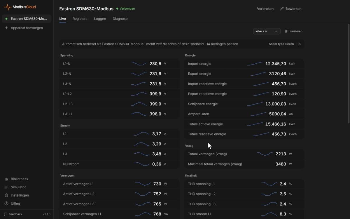
- Show suction and discharge pressure of every rack on one dashboard and compare them with the setpoints.
- Get an email when a high or low pressure switch, a thermal switch or a probe error goes active.
- Track running hours per compressor to plan maintenance and spot uneven wear.
- Keep a year of suction pressure and delivered power to see how the rack behaves at night and in summer.
- Change the suction setpoint or switch energy saving on remotely when the store opening hours change.
Installation
Connect A and B of the main RS485 port of the controller to the RS485 port of the ModbusCloud Gateway, with a termination resistor at both ends of the bus.
On the controller, set parameter 673 PtStLV to 3 (Modbus RTU), check baud rate 674 and parity 675, and restart the controller.
Note the address of the controller, which follows the family and device address parameters 671 and 672.
In ModbusCloud, add a Modbus device with that address, 9600 baud, odd parity, 8 data bits and 2 stop bits, and import this template.
Check that the suction probe and the compressor states come in and match the display of the controller.
Things to watch for
The controller does not answer at all. What should I check first?
The main RS485 port speaks Televis from the factory. Set parameter 673 to 3 for Modbus RTU and restart the controller, because the new setting only takes effect after a restart. Then check 9600 baud, odd parity and 2 stop bits, swap A and B if needed, and make sure you use the main port, not RS485 EXP.
Why does the same value appear four times, in °C, °F, bar and psi?
The controller keeps each pressure and temperature value in several display units at separate addresses. Use the version that matches the unit set on the controller and hide the others on your dashboard. The bar and psi versions have their own scaling.
Some probe values look like alarm flags of 0 and 1. Why?
For the suction, discharge and ambient probes, Eliwell also lists analogue input failure flags at the same addresses. Compare the value with the display of the controller: if it shows a pressure or temperature, the probe reading is right; if it only shows 0 or 1, treat it as a failure flag.
Can I write setpoints and commands from ModbusCloud?
Yes. Setpoints, alarm limits, compressor selection, on/off and alarm reset are writable. Change them only when you know the effect on the plant, because a wrong setpoint or a deselected compressor changes the cooling. Configuration and addressing parameters can stop the controller or the communication. Writing has to be switched on for your gateway first.
Can I connect several racks to one bus?
Yes. Give each controller its own address with the family and device address parameters, set the same baud rate and parity on all of them, and wire the bus as one line with termination at both ends.
More Eliwell templates

Want to see how it works?