

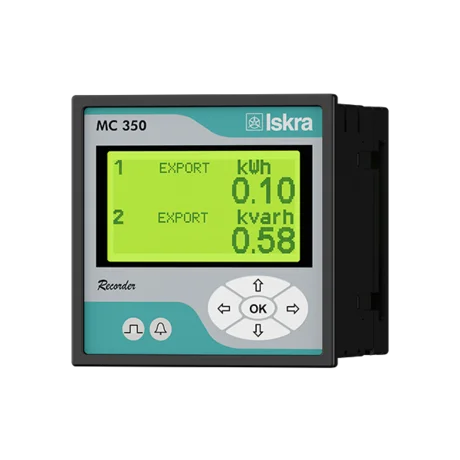
Iskra MC3x0
Iskra
Panel-mount three-phase measuring centre: voltages, currents, power, power factor, THD, demand values and energy counters over Modbus RTU.
Overview
Key readings
- Phase and line voltages
- Phase, total and neutral currents
- Active, reactive and apparent power per phase and in total
- Power factor, angles and frequency
- THD of voltage and current
- Maximum and dynamic demand values
- Energy counters with exponent and active tariff
- Normalized values in percent of nominal
Available commands
- Select the MC7x0 or MI71x0 register map
- Set the connection mode
- Set CT and VT primary and secondary
- Set current and voltage input range and nominal frequency
Use cases
- Alert when Normalized Total Active Power P exceeds 90 percent of the rated power of a feeder.
- Compare Normalized Current I1, I2 and I3 to find an unbalanced load in a distribution board.
- Track Counter E1 with Energy Counter 1 Exponent per week to report consumption per group.
- Watch Normalized THD U1 to U3 to find harmonic problems from drives or LED lighting.
- Read Max Demand Current I1 to I3 before adding load to a connection.
Installation
- 1Connect the RS485 terminals A and B of the MC3x0 to the RS485 port of your ModbusCloud Gateway. Terminate both ends of the bus.
- 2On the device open Settings, Communication and set address, speed and parity; the factory settings are 33, 115200 baud, no parity, 8 data bits, 2 stop bits.
- 3In ModbusCloud, add a Modbus device (RTU) with the same address and serial settings, then import this template.
- 4Check the link: Modbus Table Selection must read 0 and Normalized Frequency should read close to 100 percent on a 50 Hz network.
Things to watch for
- The MC3x0 does not answer on the RS485 bus. What should I check?
- Check address, speed, parity and stop bits under Settings, Communication. The factory settings are address 33, 115200 baud, no parity and 2 stop bits, which differ from many other meters. Then swap A and B and check the termination at both ends of the bus.
- The values do not match the display or seem to belong to other quantities.
- Register 40100 selects the register map. With value 1 (MI71x0 compatible) the measurements move to other addresses. Write 0 to Modbus Table Selection to use the MC7x0 map this template is built for.
- Why do Voltage U1 Raw and the other Raw values show very large numbers?
- They use the Iskra types T5, T6 and T7, with a decade exponent in the top byte. Decode them in logic, value = lower 24 bits times 10 to the power of the top byte, or use the normalized registers, which give percent of nominal with 2 decimals.
- Writing a setting returns an error.
- The basic settings 40143 to 40150 require password level 2 on the device. Enter that password on the device first, then write values within the range from the manual, for example connection mode 1 to 5 or current input range 5.00 to 200.00 percent.
Registers (156)
156 read / 9 write
| Name | Address | Function | Type | Unit | Access |
|---|---|---|---|---|---|
| Voltage U1 Raw | ••• | ••• | ••• | V | R |
| Voltage U2 Raw | ••• | ••• | ••• | V | R |
| Voltage U3 Raw | ••• | ••• | ••• | V | R |
| Average Phase Voltage Raw | ••• | ••• | ••• | V | R |
| Line Voltage U12 Raw | ••• | ••• | ••• | V | R |
| Line Voltage U23 Raw | ••• | ••• | ••• | V | R |
| Line Voltage U31 Raw | ••• | ••• | ••• | V | R |
| Average Line Voltage Raw | ••• | ••• | ••• | V | R |
| Current I1 Raw | ••• | ••• | ••• | A | R |
| Current I2 Raw | ••• | ••• | ••• | A | R |
| Current I3 Raw | ••• | ••• | ••• | A | R |
| Total Current I Raw | ••• | ••• | ••• | A | R |
| Neutral Current In Raw | ••• | ••• | ••• | A | R |
| Active Power P1 Raw | ••• | ••• | ••• | W | R |
| Active Power P2 Raw | ••• | ••• | ••• | W | R |
| Active Power P3 Raw | ••• | ••• | ••• | W | R |
| Total Active Power P Raw | ••• | ••• | ••• | W | R |
| Reactive Power Q1 Raw | ••• | ••• | ••• | var | R |
| Reactive Power Q2 Raw | ••• | ••• | ••• | var | R |
| Reactive Power Q3 Raw | ••• | ••• | ••• | var | R |
| Total Reactive Power Q Raw | ••• | ••• | ••• | var | R |
| Apparent Power S1 Raw | ••• | ••• | ••• | VA | R |
| Apparent Power S2 Raw | ••• | ••• | ••• | VA | R |
| Apparent Power S3 Raw | ••• | ••• | ••• | VA | R |
| Total Apparent Power S Raw | ••• | ••• | ••• | VA | R |
| Power Factor PF1 Raw | ••• | ••• | ••• | R | |
| Power Factor PF2 Raw | ••• | ••• | ••• | R | |
| Power Factor PF3 Raw | ••• | ••• | ••• | R | |
| Total Power Factor PF Raw | ••• | ••• | ••• | R | |
| Power Angle U1-I1 | ••• | ••• | ••• | R | |
| Power Angle U2-I2 | ••• | ••• | ••• | R | |
| Power Angle U3-I3 | ••• | ••• | ••• | R | |
| Power Angle Total | ••• | ••• | ••• | R | |
| Angle U1-U2 | ••• | ••• | ••• | R | |
| Angle U2-U3 | ••• | ••• | ••• | R | |
| Angle U3-U1 | ••• | ••• | ••• | R | |
| Frequency Raw | ••• | ••• | ••• | Hz | R |
| THD I1 | ••• | ••• | ••• | R | |
| THD I2 | ••• | ••• | ••• | R | |
| THD I3 | ••• | ••• | ••• | R | |
| THD U1 | ••• | ••• | ••• | R | |
| THD U2 | ••• | ••• | ••• | R | |
| THD U3 | ••• | ••• | ••• | R | |
| THD U12 | ••• | ••• | ••• | R | |
| THD U23 | ••• | ••• | ••• | R | |
| THD U31 | ••• | ••• | ••• | R | |
| Max Demand Active Power P Positive Raw | ••• | ••• | ••• | W | R |
| Max Demand Active Power P Negative Raw | ••• | ••• | ••• | W | R |
| Max Demand Reactive Power Inductive Raw | ••• | ••• | ••• | var | R |
| Max Demand Reactive Power Capacitive Raw | ••• | ••• | ••• | var | R |
| Max Demand Apparent Power S Raw | ••• | ••• | ••• | VA | R |
| Max Demand Current I1 Raw | ••• | ••• | ••• | A | R |
| Max Demand Current I2 Raw | ••• | ••• | ••• | A | R |
| Max Demand Current I3 Raw | ••• | ••• | ••• | A | R |
| Dynamic Demand Active Power P Positive Raw | ••• | ••• | ••• | W | R |
| Dynamic Demand Active Power P Negative Raw | ••• | ••• | ••• | W | R |
| Dynamic Demand Reactive Power Inductive Raw | ••• | ••• | ••• | var | R |
| Dynamic Demand Reactive Power Capacitive Raw | ••• | ••• | ••• | var | R |
| Dynamic Demand Apparent Power S Raw | ••• | ••• | ••• | VA | R |
| Dynamic Demand Current I1 Raw | ••• | ••• | ••• | A | R |
| Dynamic Demand Current I2 Raw | ••• | ••• | ••• | A | R |
| Dynamic Demand Current I3 Raw | ••• | ••• | ••• | A | R |
| Energy Counter 1 Exponent | ••• | ••• | ••• | R | |
| Energy Counter 2 Exponent | ••• | ••• | ••• | R | |
| Energy Counter 3 Exponent | ••• | ••• | ••• | R | |
| Energy Counter 4 Exponent | ••• | ••• | ••• | R | |
| Counter E1 | ••• | ••• | ••• | R | |
| Counter E2 | ••• | ••• | ••• | R | |
| Counter E3 | ••• | ••• | ••• | R | |
| Counter E4 | ••• | ••• | ••• | R | |
| Active Tariff | ••• | ••• | ••• | R | |
| Internal Temperature | ••• | ••• | ••• | °C | R |
| Normalized Voltage U1 | ••• | ••• | ••• | % | R |
| Normalized Voltage U2 | ••• | ••• | ••• | % | R |
| Normalized Voltage U3 | ••• | ••• | ••• | % | R |
| Normalized Average Phase Voltage | ••• | ••• | ••• | % | R |
| Normalized Line Voltage U12 | ••• | ••• | ••• | % | R |
| Normalized Line Voltage U23 | ••• | ••• | ••• | % | R |
| Normalized Line Voltage U31 | ••• | ••• | ••• | % | R |
| Normalized Average Line Voltage | ••• | ••• | ••• | % | R |
| Normalized Current I1 | ••• | ••• | ••• | % | R |
| Normalized Current I2 | ••• | ••• | ••• | % | R |
| Normalized Current I3 | ••• | ••• | ••• | % | R |
| Normalized Total Current I | ••• | ••• | ••• | % | R |
| Normalized Neutral Current In | ••• | ••• | ••• | % | R |
| Normalized Average Current I | ••• | ••• | ••• | % | R |
| Normalized Active Power P1 | ••• | ••• | ••• | % | R |
| Normalized Active Power P2 | ••• | ••• | ••• | % | R |
| Normalized Active Power P3 | ••• | ••• | ••• | % | R |
| Normalized Total Active Power P | ••• | ••• | ••• | % | R |
| Normalized Reactive Power Q1 | ••• | ••• | ••• | % | R |
| Normalized Reactive Power Q2 | ••• | ••• | ••• | % | R |
| Normalized Reactive Power Q3 | ••• | ••• | ••• | % | R |
| Normalized Total Reactive Power Q | ••• | ••• | ••• | % | R |
| Normalized Apparent Power S1 | ••• | ••• | ••• | % | R |
| Normalized Apparent Power S2 | ••• | ••• | ••• | % | R |
| Normalized Apparent Power S3 | ••• | ••• | ••• | % | R |
| Normalized Total Apparent Power S | ••• | ••• | ••• | % | R |
| Normalized Power Factor PF1 | ••• | ••• | ••• | % | R |
| Normalized Power Factor PF2 | ••• | ••• | ••• | % | R |
| Normalized Power Factor PF3 | ••• | ••• | ••• | % | R |
| Normalized Total Power Factor PF | ••• | ••• | ••• | % | R |
| Normalized Cap Ind PF1 | ••• | ••• | ••• | % | R |
| Normalized Cap Ind PF2 | ••• | ••• | ••• | % | R |
| Normalized Cap Ind PF3 | ••• | ••• | ••• | % | R |
| Normalized Cap Ind PF Total | ••• | ••• | ••• | % | R |
| Normalized Power Angle U1-I1 | ••• | ••• | ••• | % | R |
| Normalized Power Angle U2-I2 | ••• | ••• | ••• | % | R |
| Normalized Power Angle U3-I3 | ••• | ••• | ••• | % | R |
| Normalized Power Angle Total | ••• | ••• | ••• | % | R |
| Normalized Angle U1-U2 | ••• | ••• | ••• | % | R |
| Normalized Angle U2-U3 | ••• | ••• | ••• | % | R |
| Normalized Angle U3-U1 | ••• | ••• | ••• | % | R |
| Normalized Frequency | ••• | ••• | ••• | % | R |
| Normalized THD I1 | ••• | ••• | ••• | % | R |
| Normalized THD I2 | ••• | ••• | ••• | % | R |
| Normalized THD I3 | ••• | ••• | ••• | % | R |
| Normalized THD U1 | ••• | ••• | ••• | % | R |
| Normalized THD U2 | ••• | ••• | ••• | % | R |
| Normalized THD U3 | ••• | ••• | ••• | % | R |
| Normalized THD U12 | ••• | ••• | ••• | % | R |
| Normalized THD U23 | ••• | ••• | ••• | % | R |
| Normalized THD U31 | ••• | ••• | ••• | % | R |
| Normalized Max Demand Active Power P Positive | ••• | ••• | ••• | % | R |
| Normalized Max Demand Active Power P Negative | ••• | ••• | ••• | % | R |
| Normalized Max Demand Reactive Power Inductive | ••• | ••• | ••• | % | R |
| Normalized Max Demand Reactive Power Capacitive | ••• | ••• | ••• | % | R |
| Normalized Max Demand Apparent Power S | ••• | ••• | ••• | % | R |
| Normalized Max Demand Current I1 | ••• | ••• | ••• | % | R |
| Normalized Max Demand Current I2 | ••• | ••• | ••• | % | R |
| Normalized Max Demand Current I3 | ••• | ••• | ••• | % | R |
| Normalized Dynamic Demand Active Power P Positive | ••• | ••• | ••• | % | R |
| Normalized Dynamic Demand Active Power P Negative | ••• | ••• | ••• | % | R |
| Normalized Dynamic Demand Reactive Power Inductive | ••• | ••• | ••• | % | R |
| Normalized Dynamic Demand Reactive Power Capacitive | ••• | ••• | ••• | % | R |
| Normalized Dynamic Demand Apparent Power S | ••• | ••• | ••• | % | R |
| Normalized Dynamic Demand Current I1 | ••• | ••• | ••• | % | R |
| Normalized Dynamic Demand Current I2 | ••• | ••• | ••• | % | R |
| Normalized Dynamic Demand Current I3 | ••• | ••• | ••• | % | R |
| Normalized Energy Counter 1 | ••• | ••• | ••• | R | |
| Normalized Energy Counter 2 | ••• | ••• | ••• | R | |
| Normalized Energy Counter 3 | ••• | ••• | ••• | R | |
| Normalized Energy Counter 4 | ••• | ••• | ••• | R | |
| Normalized Active Tariff | ••• | ••• | ••• | R | |
| Normalized Internal Temperature | ••• | ••• | ••• | % | R |
| Calibration Voltage | ••• | ••• | ••• | R | |
| Calibration Current | ••• | ••• | ••• | R | |
| Modbus Table Selection | ••• | ••• | ••• | R/W | |
| Connection Mode | ••• | ••• | ••• | R/W | |
| CT Secondary | ••• | ••• | ••• | R/W | |
| CT Primary | ••• | ••• | ••• | R/W | |
| VT Secondary | ••• | ••• | ••• | R/W | |
| VT Primary | ••• | ••• | ••• | R/W | |
| Current Input Range | ••• | ••• | ••• | % | R/W |
| Voltage Input Range | ••• | ••• | ••• | % | R/W |
| Nominal Frequency | ••• | ••• | ••• | Hz | R/W |
Loading registers…
Read the Iskra MC3x0 remotely
We load the templates onto the gateway and set up your portal, you connect it at your customer's site. Tell us briefly what you need and we'll send a proposal.
From €295 + €149/year.
Prefer to configure it yourself? Order the gateway in the shop·Or see the live demo first
More RTU templates

Alnor HRU
Alnor Systemy Wentylacji Sp. z o. o.
Controls and monitors Alnor heat recovery ventilation units via Modbus RTU.

Alnor HRU-P
Alnor Systemy Wentylacji Sp. z o. o.
Controls Alnor HRU-P heat recovery ventilation units via Modbus RTU.

connecdoor.controller
connecdoor
Controls and monitors smart door access points via RS485
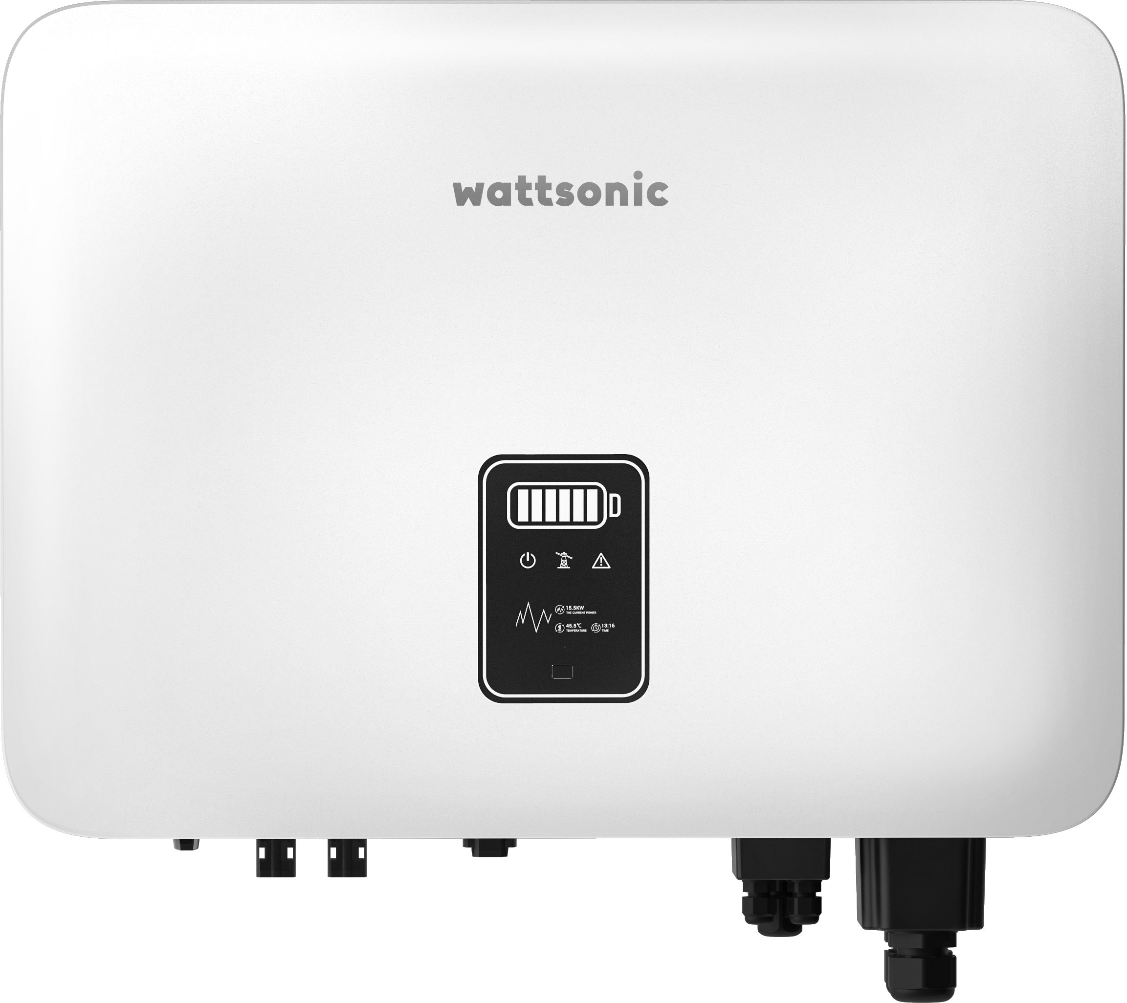
Wattsonic - Schmachtl Sun Energy Box
Wattsonic
Monitors Schmachtl Wattsonic hybrid inverter via Modbus RTU

Heidelberg Wallbox Energy Control
AMPERFIED GmbH
Controls and monitors Heidelberg Wallbox Energy Control EV charger via Modbus RTU.
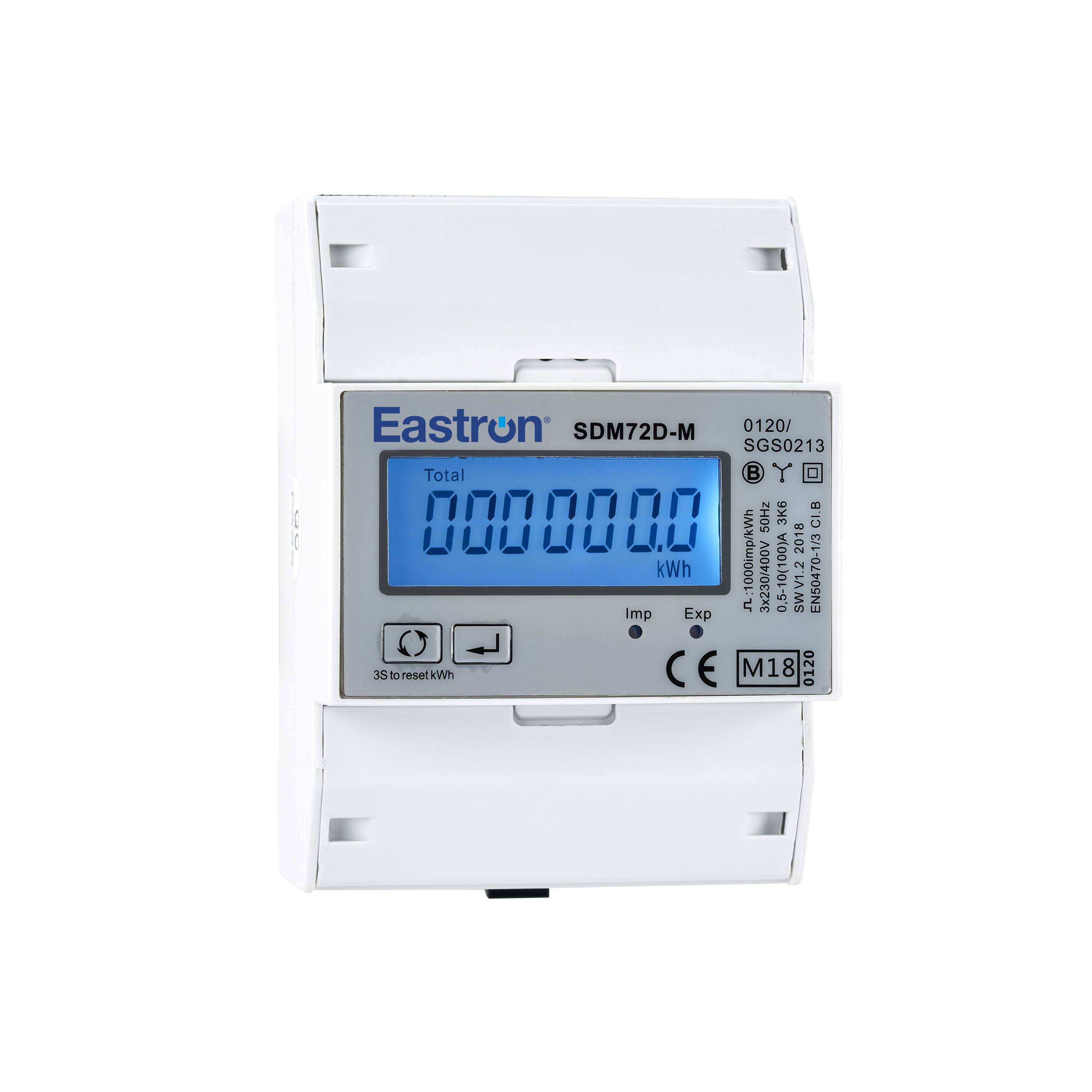
Eastron SDM72D-M
Eastron
Reads energy metering values from an Eastron SDM72D-M three-phase meter.