
Riello UPS NetMan 208
Network card for Riello UPS systems with voltages, load, battery status and alarms over Modbus TCP.
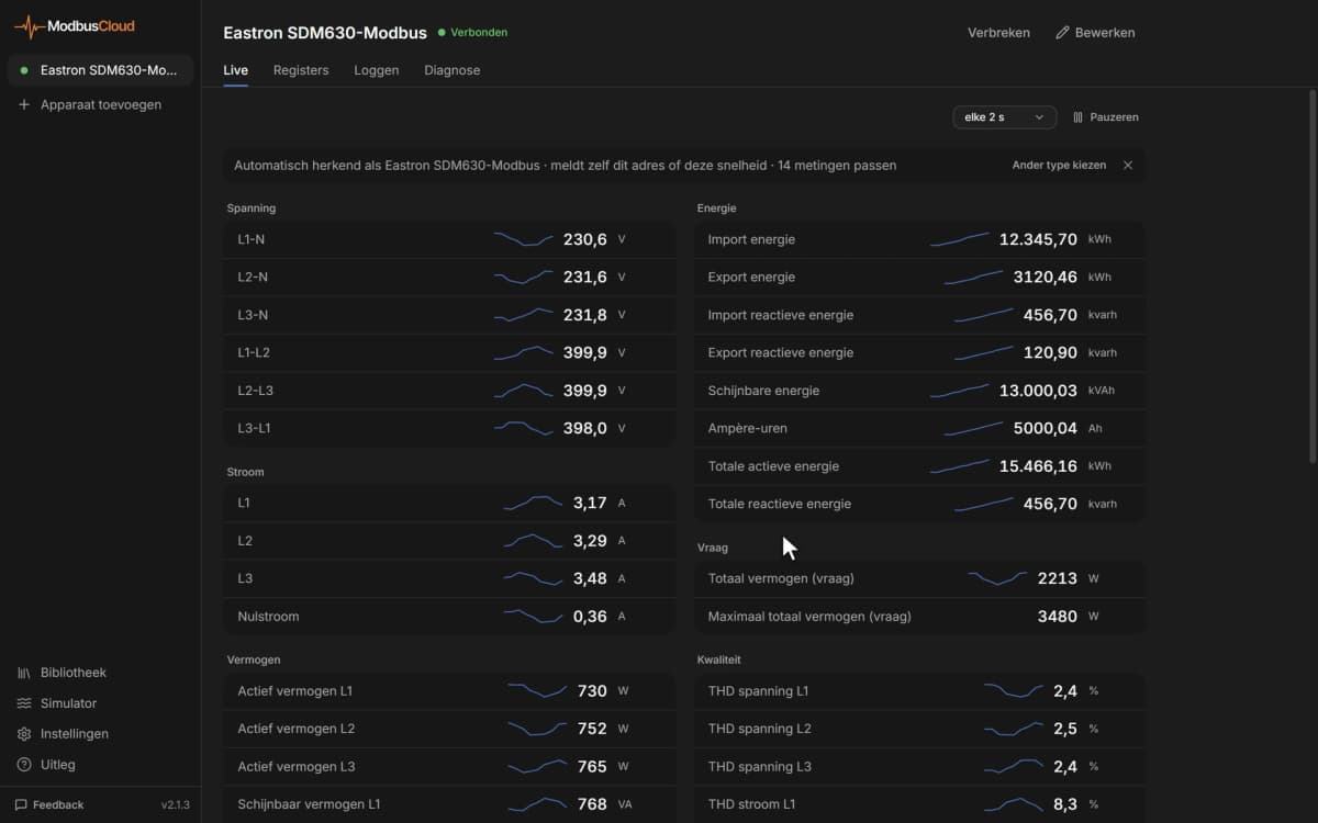
The Riello UPS NetMan 208 is a network card that makes the status of a Riello UPS available on the local network, from mains and output voltages to battery charge and alarms. This Modbus TCP template reads voltages, load, battery charge, back-up time and the alarm flags, and lets you send shutdown and battery test commands from ModbusCloud.
- Protocol
- Modbus TCP
- Connection
- Ethernet, Modbus TCP
- Registers
- 44, read and write
- Brand
- Riello UPS
- Key readings
- Input and output voltage · Load per phase · Battery charge · Remaining back-up time · Battery voltage · UPS temperature · On battery · UPS failure
- Available commands
- Shutdown and restore command · Battery test · Shutdown delay · Restore delay
- Compatible models
- NetMan 208 · Riello UPS with a NetMan 208 network card
- Last updated
Registers (44)
44 read, 3 write
| Name | Unit | Access | Address (Hidden until you enter your email) | Function (hidden) | Type (hidden) |
|---|---|---|---|---|---|
| Input Voltage L1 | V | Read | 11 | FC03 | uint16 |
| Input Voltage L2 | V | Read | 12 | FC03 | uint16 |
| Input Voltage L3 | V | Read | 13 | FC03 | uint16 |
| Input Frequency | Hz | Read | 17 | FC03 | uint16 |
| Output Voltage L1 | V | Read | 25 | FC03 | uint16 |
| Output Voltage L2 | V | Read | |||
| Output Voltage L3 | V | Read | |||
| Output Frequency | Hz | Read | |||
| Load L1 | % | Read | |||
| Load L2 | % | Read | |||
| Load L3 | % | Read | |||
| Bypass Voltage L1 | V | Read | |||
| Bypass Voltage L2 | V | Read | |||
| Bypass Voltage L3 | V | Read | |||
| Bypass Frequency | Hz | Read | |||
| Battery Voltage | V | Read | |||
| Battery Charge | % | Read | |||
| Autonomy | min | Read | |||
| Internal UPS Temperature | °C | Read | |||
| Test In Progress | Read | ||||
| Shutdown Active | Read | ||||
| Battery Charged | Read | ||||
| Bypass Bad | Read | ||||
| Normal Operation | Read | ||||
| On Bypass | Read | ||||
| Battery Low | Read | ||||
| Battery Working | Read | ||||
| UPS Locked | Read | ||||
| Output Powered | Read | ||||
| Input Mains Present | Read | ||||
| Temperature Alarm | Read | ||||
| Overload Alarm | Read | ||||
| UPS Failure | Read | ||||
| Communication Lost With UPS | Read | ||||
| Command Code | Read and write | ||||
| Shutdown Delay Time | s | Read and write | |||
| Restore Delay Time | min | Read and write | |||
| Command Result | Read | ||||
| Output Nominal Voltage | V | Read | |||
| Output Nominal Frequency | Hz | Read | |||
| Output Nominal Apparent Power | kVA | Read | |||
| Output Nominal Active Power | kW | Read | |||
| Battery Nominal Capacity | Read | ||||
| Battery Benches | Read |
Loading registers…
Send your device list
If a device is not in the library yet, we build the template for free as soon as we have the register data.
Use cases
- Get an email from ModbusCloud as soon as the UPS switches to battery or loses mains power.
- Set an alarm on remaining back-up time so you know when the battery can no longer carry the load.
- Track load per phase in the history to see whether the UPS still has room for new equipment.
- Alert on overload, temperature and UPS failure flags across all sites in one fleet overview.
- Start a battery test from the portal and read the command result afterwards.
- Compare battery voltage and charge over months to spot an ageing battery before it fails.
Installation
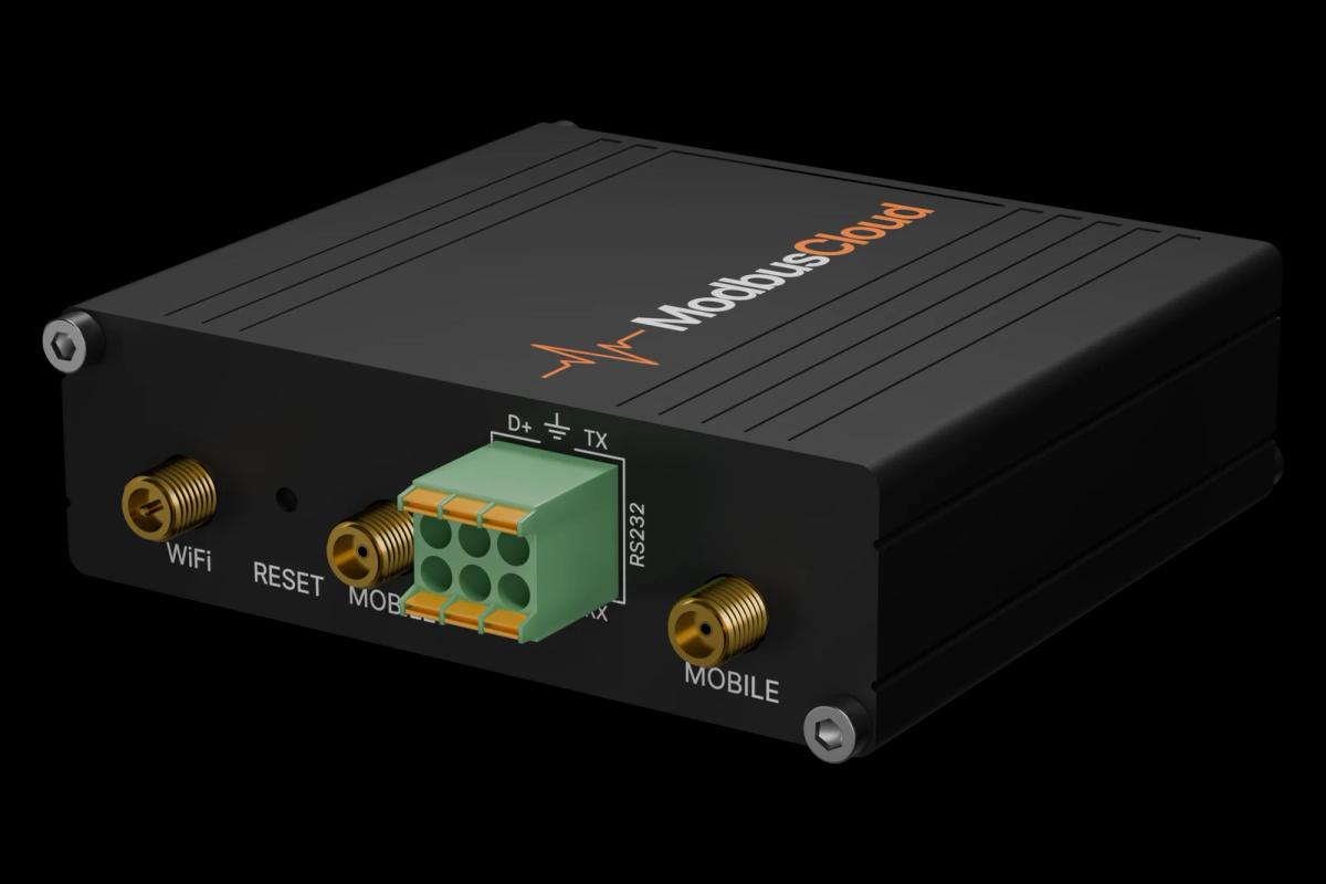
Connect the NetMan 208 to the network where the ModbusCloud Gateway hangs, or to the Gateway's LAN port.
Give the card a fixed IP address or a DHCP reservation, and turn on Modbus in its web interface under Modbus/BACnet.
In ModbusCloud, add a Modbus TCP device with the IP address of the card, port 502 and unit ID 1, then import this template.
Check that Input Mains Present reads 1 and that the output voltage matches the nominal voltage.
Things to watch for
The card does not answer on port 502. What should I check?
Check that Modbus is turned on in the NetMan 208 web interface, that the IP address is correct and that the Gateway and the card are in the same network or can route to each other. A firewall between them must allow TCP port 502.
Why do the L2 and L3 values show 65535?
On a single-phase UPS the registers for phase 2 and 3 report 65535 because those phases do not exist. Hide them in your dashboard or ignore them in your alarm rules.
Communication Lost With UPS is 1. Is the UPS down?
Not necessarily. The flag means the card no longer talks to the UPS itself. Check that the card is seated properly in the slot and restart the card. While the flag is set, the other values are not current.
What should I know before writing a command?
Command 1 shuts the UPS down and removes power from the load after the shutdown delay. Command 2 also restores it after the restore delay. Set the delay registers first, write the command code, then read Command Result: the code itself means accepted, code plus 100 means the UPS did not handle it. Command 3 cancels a pending shutdown.
More Riello UPS templates

Want to see how it works?