








Victron Modbus Integration
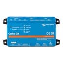
Monitors Victron energy systems via CerboGX Modbus TCP connection.
This template reads AC consumption, grid power, battery voltage, state of charge, and battery power from a Victron Energy system via a CerboGX over Modbus TCP. It supports system, VeBus, and SmartSolar charger device types, each addressed by their own Unit ID.
- Protocol
- Modbus TCP
- Connection
- Ethernet, Modbus TCP
- Registers
- 9, read only
- Brand
- Victron Energy B.V.
- Key readings
- AC Consumption L1 to L3 · Grid Power L1 to L3 · Battery Power (System) · Battery State of Charge (System) · Battery Voltage (System)
- Compatible models
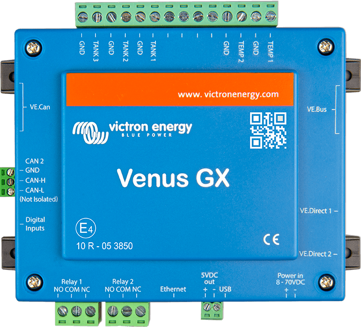
- Victron CerboGX · Victron SmartSolar · Victron VeBus
- Last updated
Registers (9)
9 read, 0 write
| Name | Unit | Access | Address (Hidden until you enter your email) | Function (hidden) | Type (hidden) |
|---|---|---|---|---|---|
| AC Consumption L1 | W | Read | |||
| AC Consumption L2 | W | Read | |||
| AC Consumption L3 | W | Read | |||
| Battery Power (System) | W | Read | |||
| Battery State of Charge (System) | % | Read | |||
| Battery Voltage (System) | V | Read | |||
| Grid L2 | V | Read | |||
| Grid L3 | V | Read | |||
| Grid L1 | V | Read |
Loading registers…
Send your device list
If a device is not in the library yet, we build the template for free as soon as we have the register data.
Use cases
- Monitor AC consumption per phase and grid power on a live cloud dashboard for your customer.
- Track battery state of charge and voltage over time to detect degradation or undersizing.
- Create an alert when battery state of charge drops below a critical threshold for more than 15 minutes.
- Compare SmartSolar charger output with total AC consumption to evaluate self-consumption ratios.
- Generate daily and monthly energy reports for off-grid or hybrid Victron installations.
- Verify correct system operation remotely after commissioning a new Victron setup.
Installation
Enable Modbus TCP in the CerboGX settings under Services and note the IP address and port (default 502).
Navigate to Available Services on the CerboGX and record the Unit ID for com.victronenergy.system, com.victronenergy.vebus, and com.victronenergy.solarcharger.
Connect your ModbusCloud Gateway to the same local network as the CerboGX.
Import the Victron Modbus Integration template in the ModbusCloud platform and enter the CerboGX IP address and port.
Configure each Modbus device in the template with the correct Unit ID as noted from the CerboGX.
Verify that live readings for AC consumption, grid power, and battery data appear on your ModbusCloud dashboard.
Things to watch for
I see no data after importing the template. What should I check first?
Confirm that Modbus TCP is enabled on the CerboGX under Services. Then verify that the ModbusCloud gateway and the CerboGX are on the same network, or that TCP port 502 is open through any firewall between them.
How do I find the correct Unit ID for each Victron device?
On the CerboGX, go to Settings, then Services, then Available Services. Each device type (system, vebus, solarcharger) is listed with its Unit ID. Enter these IDs in the corresponding Modbus device entries in the template.
Can I add more registers, for example tank levels or additional MPPT chargers?
Yes. Download the official Victron Modbus TCP register file from the Victron GitHub repository. It lists all available registers with addresses, data types, and scale factors. Add new registers in the ModbusCloud template accordingly.
Do I need RS-485 wiring for this template?
No. The CerboGX communicates over Modbus TCP via Ethernet or Wi-Fi. Only a standard network connection between the ModbusCloud gateway and the CerboGX is required.
More Victron Energy B.V. templates
Want to see how it works?
