








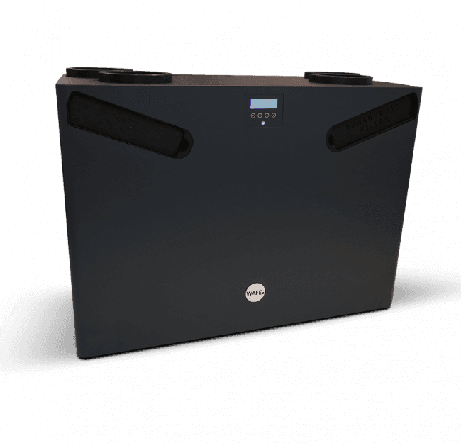
WAFE 350 heat recovery unit
Monitors and controls a WAFE 350 heat recovery ventilation unit via Modbus TCP
The WAFE 350 is a heat recovery ventilation unit (ERV/HRV) that communicates via Modbus TCP. This template reads temperatures, humidity, CO2 levels, fan speeds, and filter status, and allows control of ventilation modes, airflow setpoints, bypass settings, and climate setpoints.
- Protocol
- Modbus TCP
- Connection
- Ethernet, Modbus TCP
- Registers
- 66, read and write
- Brand
- WAFE
- Key readings
- Temperatures (outside/inside in/out) · Humidity (outside/inside in/out) · CO2 value · Fresh/exhaust fan speed and flow · Filter fresh/exhaust warnings · Machine error and frost status
- Available commands
- Operating modes (sleep, boost, manual, fireplace) · Nominal/minimal/maximal flow setpoints · CO2 and RH setpoints · Bypass settings
- Compatible models
- WAFE 350
- Last updated
Registers (66)
66 read, 32 write
| Name | Unit | Access | Address (Hidden until you enter your email) | Function (hidden) | Type (hidden) |
|---|---|---|---|---|---|
| Sleep mode | Read and write | ||||
| Boost short | Read and write | ||||
| Boost long | Read and write | ||||
| Holiday mode | Read and write | ||||
| Circulation | Read and write | ||||
| Fireplace option | Read and write | ||||
| Silent option | Read and write | ||||
| Inteligent mode | Read and write | ||||
| Scheduler mode | Read and write | ||||
| Manual mode | Read and write | ||||
| Dehum mode | Read and write | ||||
| Safe dehum | Read and write | ||||
| PID drive | Read and write | ||||
| Bypass regime | Read and write | ||||
| Week noact regime | Read and write | ||||
| Week active regime | Read and write | ||||
| Bypass mode | Read | ||||
| Week mode active | Read | ||||
| Sensor temperature outside in | Read | ||||
| Sensor temperature inside in | Read | ||||
| Sensor temperarure inside out | Read | ||||
| Sensor humidity outside in | Read | ||||
| Sensor humidity inside in | Read | ||||
| Sensor humidity inside out | Read | ||||
| Sensor humidity outside out | Read | ||||
| Sensor fresh filter pressure | Read | ||||
| Sensor exhaust filter pressure | Read | ||||
| Sensor CO2 | Read | ||||
| Flaps status | Read | ||||
| Filter fresh warning | Read | ||||
| Filter exhaust warning | Read | ||||
| Filter fresh clogged | Read | ||||
| Filter exhaust clogged | Read | ||||
| Low temperature of fresh air - frost | Read | ||||
| Machine stopped on error | Read | ||||
| Temperature outside in | °C | Read | |||
| Temperature inside in | °C | Read | |||
| Temperature inside out | °C | Read | |||
| Temperature outside out | °C | Read | |||
| Humidity outside in | % | Read | |||
| Humidity inside in | % | Read | |||
| Humidity inside out | % | Read | |||
| Humidity outside out | % | Read | |||
| CO2 value | ppm | Read | |||
| Fresh air fan percentage | % | Read | |||
| Fresh air fan flow | m³/h | Read | |||
| Freshair fan rpm | rpm | Read | |||
| Exhaustair fan percentage | % | Read | |||
| Exhaust air fan flow | m³/h | Read | |||
| Exhaust fan rpm | rpm | Read | |||
| Nominal Flow | m³/h | Read and write | |||
| Minimal Flow | m³/h | Read and write | |||
| Maximal Flow | m³/h | Read and write | |||
| Manual Flow | m³/h | Read and write | |||
| Sillent Flow Max | m³/h | Read and write | |||
| Bypass Month Start | Read and write | ||||
| Bypass Month End | Read and write | ||||
| Bypass Out Temp Min | °C | Read and write | |||
| Bypass Inside Temp Min | °C | Read and write | |||
| CO2 setpoint | ppm | Read and write | |||
| RH inside out setpoint | % | Read and write | |||
| Bypass remove | Read and write | ||||
| Bypass flow | m³/h | Read and write | |||
| Boost short duration | min | Read and write | |||
| Boost long duration | min | Read and write | |||
| Circulation duration | min | Read and write |
Loading registers…
Send your device list
If a device is not in the library yet, we build the template for free as soon as we have the register data.
Use cases
- Monitor supply and extract temperatures, humidity, and CO2 on a live cloud dashboard for your customer.
- Create an alert when the fresh air or exhaust air filter warning activates so the installer can schedule maintenance.
- Log airflow rates and fan speeds over time to verify that the ventilation system meets design specifications.
- Switch between sleep, boost, and manual ventilation modes remotely via the ModbusCloud platform.
- Set CO2 and relative humidity setpoints remotely to fine-tune demand-controlled ventilation without a site visit.
- Receive a notification when a machine error or frost protection event occurs to enable rapid troubleshooting.
Installation
Connect the ModbusCloud Gateway to the same IP network as the WAFE 350 unit and verify TCP connectivity.
Ensure Modbus TCP is enabled on the WAFE 350 and note the unit's IP address and Modbus TCP port (typically port 502).
Set the correct Modbus slave address on the WAFE 350 to match the address configured in the ModbusCloud template.
Import the WAFE 350 template in the ModbusCloud portal and assign it to the gateway.
Increase the Modbus polling interval and response timeout in the gateway configuration, as the WAFE 350 may respond slowly.
If a chimney is present, configure the fireplace mode input and connect it to a chimney door contact or temperature sensor.
Things to watch for
The gateway reports frequent timeouts when polling the WAFE 350. What can I do?
The WAFE 350 is known to have relatively long Modbus response times. Increase the response timeout on the gateway to at least 2000 ms and reduce the polling frequency. Splitting reads into smaller register groups using cascaded status blocks can also help.
Do I need to enable Modbus TCP on the WAFE 350 before using this template?
Yes. Modbus TCP must be activated in the WAFE 350 configuration menu. Consult the WAFE installation manual for the exact setting location and ensure the unit has a valid IP address on the same subnet as the gateway.
When should I activate the fireplace mode?
Activate fireplace mode whenever the building has a chimney or open flue appliance. Connect a chimney door contact or chimney temperature sensor to trigger this mode automatically and prevent dangerous back-drafting of combustion gases.
How do I display the full system status on the dashboard?
The WAFE 350 status is split across multiple register groups. Use cascaded status function blocks in your configuration, each reading one subsystem. A main block then combines these partial readings into a single status overview on the ModbusCloud dashboard.





Want to see how it works?
