Wavin Sentio Heating Circuits and DHW
Mixing circuits, hot water and heat source of a Wavin Sentio installation.
This template covers the heating side of a Wavin Sentio installation: the mixing circuits (ITC), the heating and cooling circuits (HCC), the Calefa hot water unit, the hot water tank and, from firmware package 16, the boiler or heat pump and the buffer tank. Use it next to the Wavin Sentio room template to watch supply temperatures and alarms and to tune heat curves from ModbusCloud.
- Protocol
- Modbus RTU
- Connection
- RS485, 19200 baud
- Registers
- 302, read and write
- Brand
- Wavin
- Key readings
- Supply temperature per circuit · Return temperature · Pump state · Hot water temperature · Tank temperature · Buffer tank temperatures · Sensor and safety alarms
- Available commands
- Heat curve type and slope · Minimum and maximum supply temperature · Return temperature limits · Hot water setpoint · Tank setpoints · High temperature cut-off
- Compatible models
- Sentio CCU-208
- Last updated
Registers (302)
302 read, 149 write
| Name | Unit | Access | Address (Hidden until you enter your email) | Function (hidden) | Type (hidden) |
|---|---|---|---|---|---|
| DHW Warning | Read | 6501 | FC02 | bool | |
| DHW Error | Read | 6502 | FC02 | bool | |
| DHW Warning Retentive Low Energy | Read | 6503 | FC02 | bool | |
| DHW Error DHW Temperature High | Read | 6504 | FC02 | bool | |
| DHW Error Motor Failure | Read | 6505 | FC02 | bool | |
| DHW Error Source Inlet Sensor (DHI) | Read | ||||
| DHW Error Source Return Sensor (DHO) | Read | ||||
| DHW Error DHW Sensor | Read | ||||
| DHW Error Cold Water Sensor (DCW) | Read | ||||
| DHW Warning Pressure High | Read | ||||
| DHW Warning Pressure Low | Read | ||||
| DHW Error Pressure Critical Low | Read | ||||
| DHW Error Flow Sensor | Read | ||||
| DHW Desired Temperature | °C | Read | |||
| DHW State | Read | ||||
| DHW Blocking Source | Read | ||||
| DHW Circulation State | Read | ||||
| DHW Measured Temperature | °C | Read | |||
| DHW Source Inlet Temperature | °C | Read | |||
| DHW Source Return Temperature | °C | Read | |||
| DHW Pressure | Read | ||||
| DHW Cold Water Temperature | °C | Read | |||
| DHW Cold Water Flow | l/h | Read | |||
| DHW Valve Position | Read | ||||
| DHW Boost Pump State | Read | ||||
| DHW Name | Read and write | ||||
| DHW Mode | Read and write | ||||
| DHW Display Lock | Read and write | ||||
| DHW Block Request | Read and write | ||||
| DHW Power Consumption Limit | Read and write | ||||
| DHW Temperature Setpoint | °C | Read and write | |||
| DHW Bypass Temperature | °C | Read and write | |||
| DHW Circulation Pump Present | Read and write | ||||
| DHW Circulation Inlet Temperature | °C | Read and write | |||
| DHW Exclude From Vacation | Read and write | ||||
| DHW Exclude From Standby | Read and write | ||||
| DHW Boost Pump Mode | Read and write | ||||
| DHW Tank Warning | Read | ||||
| DHW Tank Error | Read | ||||
| DHW Tank Warning Cleaning Process Fail | Read | ||||
| DHW Tank Error Tank Sensor | Read | ||||
| DHW Tank Error Circulation Return Sensor | Read | ||||
| DHW Tank Error Source Return Sensor | Read | ||||
| DHW Tank Error Source Inlet Sensor | Read | ||||
| DHW Tank Warning Source Inlet Too Low | Read | ||||
| DHW Tank Warning Peripheral Low Battery | Read | ||||
| DHW Tank Error Peripheral Unreachable | Read | ||||
| DHW Tank Measured Temperature | °C | Read | |||
| DHW Tank Desired Temperature | °C | Read | |||
| DHW Tank State | Read | ||||
| DHW Tank Blocking Source | Read | ||||
| DHW Tank Circulation State | Read | ||||
| DHW Tank Circulation Return Temperature | °C | Read | |||
| DHW Tank Source Inlet Temperature | °C | Read | |||
| DHW Tank Source Return Temperature | °C | Read | |||
| DHW Tank Name | Read and write | ||||
| DHW Tank Mode | Read and write | ||||
| DHW Tank Circulation Cooldown Time | Read and write | ||||
| DHW Tank Circulation Stop Difference | Read and write | ||||
| DHW Tank Source Return Limit | °C | Read and write | |||
| DHW Tank Temperature Setpoint | °C | Read and write | |||
| DHW Tank Vacation Setpoint | °C | Read and write | |||
| DHW Tank Cleaning Setpoint | °C | Read and write | |||
| DHW Tank Standby Setpoint | °C | Read and write | |||
| DHW Tank Exclude From Vacation | Read and write | ||||
| DHW Tank Exclude From Standby | Read and write | ||||
| ITC1 Warning | Read | ||||
| ITC1 Error | Read | ||||
| ITC1 Error Inlet Sensor | Read | ||||
| ITC1 Error Servo | Read | ||||
| ITC1 Error Return Sensor | Read | ||||
| ITC1 Error Outdoor Sensor | Read | ||||
| ITC1 High Temperature Cut-off Active | Read | ||||
| ITC1 Frost Protection Active | Read | ||||
| ITC1 State | Read | ||||
| ITC1 Blocking Source | Read | ||||
| ITC1 Pump Demand | Read | ||||
| ITC1 Pump State | Read | ||||
| ITC1 Measured Inlet Temperature | °C | Read | |||
| ITC1 Desired Inlet Temperature | °C | Read | |||
| ITC1 Measured Return Temperature | °C | Read | |||
| ITC1 Main Supplier Temperature | °C | Read | |||
| ITC1 Servo Position Request | % | Read | |||
| ITC1 Desired Room Temperature By Consumers | °C | Read | |||
| ITC1 Name | Read and write | ||||
| ITC1 Regulator P Value | Read and write | ||||
| ITC1 Regulator I Value | Read and write | ||||
| ITC1 Regulator Hysteresis | Read and write | ||||
| ITC1 Heat Curve Type | Read and write | ||||
| ITC1 Heat Curve Manual Slope | Read and write | ||||
| ITC1 Heat Curve Parallel Displacement | Read and write | ||||
| ITC1 Heat Curve Min Inlet | °C | Read and write | |||
| ITC1 Heat Curve Max Inlet | °C | Read and write | |||
| ITC1 Heat Curve Gain | Read and write | ||||
| ITC1 Return Limiter Function | Read and write | ||||
| ITC1 Return Max Limit | °C | Read and write | |||
| ITC1 Return Max Limiter Gain | Read and write | ||||
| ITC1 Return Max Limiter Priority | Read and write | ||||
| ITC1 Return Min Limit | °C | Read and write | |||
| ITC1 Return Min Limiter Gain | Read and write | ||||
| ITC1 Optimization Boost | Read and write | ||||
| ITC1 Optimization Boost Flow | Read and write | ||||
| ITC1 Optimization Ramping | Read and write | ||||
| ITC1 Optimization Ramping Time | Read and write | ||||
| ITC1 Frost Protection Mode | Read and write | ||||
| ITC1 Frost Protection Temperature | °C | Read and write | |||
| ITC1 High Temperature Cut-off Mode | Read and write | ||||
| ITC1 High Temperature Cut-off Temperature | °C | Read and write | |||
| ITC1 Cooling Regulator P Value | Read and write | ||||
| ITC1 Cooling Regulator I Value | Read and write | ||||
| ITC1 Cooling Regulator Hysteresis | Read and write | ||||
| ITC1 Cooling Inlet Min | °C | Read and write | |||
| ITC1 Cooling Inlet Max | °C | Read and write | |||
| ITC2 Warning | Read | ||||
| ITC2 Error | Read | ||||
| ITC2 Error Inlet Sensor | Read | ||||
| ITC2 Error Servo | Read | ||||
| ITC2 Error Return Sensor | Read | ||||
| ITC2 Error Outdoor Sensor | Read | ||||
| ITC2 High Temperature Cut-off Active | Read | ||||
| ITC2 Frost Protection Active | Read | ||||
| ITC2 State | Read | ||||
| ITC2 Blocking Source | Read | ||||
| ITC2 Pump Demand | Read | ||||
| ITC2 Pump State | Read | ||||
| ITC2 Measured Inlet Temperature | °C | Read | |||
| ITC2 Desired Inlet Temperature | °C | Read | |||
| ITC2 Measured Return Temperature | °C | Read | |||
| ITC2 Main Supplier Temperature | °C | Read | |||
| ITC2 Servo Position Request | % | Read | |||
| ITC2 Desired Room Temperature By Consumers | °C | Read | |||
| ITC2 Name | Read and write | ||||
| ITC2 Regulator P Value | Read and write | ||||
| ITC2 Regulator I Value | Read and write | ||||
| ITC2 Regulator Hysteresis | Read and write | ||||
| ITC2 Heat Curve Type | Read and write | ||||
| ITC2 Heat Curve Manual Slope | Read and write | ||||
| ITC2 Heat Curve Parallel Displacement | Read and write | ||||
| ITC2 Heat Curve Min Inlet | °C | Read and write | |||
| ITC2 Heat Curve Max Inlet | °C | Read and write | |||
| ITC2 Heat Curve Gain | Read and write | ||||
| ITC2 Return Limiter Function | Read and write | ||||
| ITC2 Return Max Limit | °C | Read and write | |||
| ITC2 Return Max Limiter Gain | Read and write | ||||
| ITC2 Return Max Limiter Priority | Read and write | ||||
| ITC2 Return Min Limit | °C | Read and write | |||
| ITC2 Return Min Limiter Gain | Read and write | ||||
| ITC2 Optimization Boost | Read and write | ||||
| ITC2 Optimization Boost Flow | Read and write | ||||
| ITC2 Optimization Ramping | Read and write | ||||
| ITC2 Optimization Ramping Time | Read and write | ||||
| ITC2 Frost Protection Mode | Read and write | ||||
| ITC2 Frost Protection Temperature | °C | Read and write | |||
| ITC2 High Temperature Cut-off Mode | Read and write | ||||
| ITC2 High Temperature Cut-off Temperature | °C | Read and write | |||
| ITC2 Cooling Regulator P Value | Read and write | ||||
| ITC2 Cooling Regulator I Value | Read and write | ||||
| ITC2 Cooling Regulator Hysteresis | Read and write | ||||
| ITC2 Cooling Inlet Min | °C | Read and write | |||
| ITC2 Cooling Inlet Max | °C | Read and write | |||
| Calefa ITC Warning | Read | ||||
| Calefa ITC Error | Read | ||||
| Calefa ITC Error Inlet Sensor | Read | ||||
| Calefa ITC Error Servo | Read | ||||
| Calefa ITC Error Return Sensor | Read | ||||
| Calefa ITC Error Outdoor Sensor | Read | ||||
| Calefa ITC High Temperature Cut-off Active | Read | ||||
| Calefa ITC Frost Protection Active | Read | ||||
| Calefa ITC State | Read | ||||
| Calefa ITC Blocking Source | Read | ||||
| Calefa ITC Pump Demand | Read | ||||
| Calefa ITC Pump State | Read | ||||
| Calefa ITC Measured Inlet Temperature | °C | Read | |||
| Calefa ITC Desired Inlet Temperature | °C | Read | |||
| Calefa ITC Measured Return Temperature | °C | Read | |||
| Calefa ITC Main Supplier Temperature | °C | Read | |||
| Calefa ITC Servo Position Request | % | Read | |||
| Calefa ITC Desired Room Temperature By Consumers | °C | Read | |||
| Calefa ITC Name | Read and write | ||||
| Calefa ITC Regulator P Value | Read and write | ||||
| Calefa ITC Regulator I Value | Read and write | ||||
| Calefa ITC Regulator Hysteresis | Read and write | ||||
| Calefa ITC Heat Curve Type | Read and write | ||||
| Calefa ITC Heat Curve Manual Slope | Read and write | ||||
| Calefa ITC Heat Curve Parallel Displacement | Read and write | ||||
| Calefa ITC Heat Curve Min Inlet | °C | Read and write | |||
| Calefa ITC Heat Curve Max Inlet | °C | Read and write | |||
| Calefa ITC Heat Curve Gain | Read and write | ||||
| Calefa ITC Return Limiter Function | Read and write | ||||
| Calefa ITC Return Max Limit | °C | Read and write | |||
| Calefa ITC Return Max Limiter Gain | Read and write | ||||
| Calefa ITC Return Max Limiter Priority | Read and write | ||||
| Calefa ITC Return Min Limit | °C | Read and write | |||
| Calefa ITC Return Min Limiter Gain | Read and write | ||||
| Calefa ITC Optimization Boost | Read and write | ||||
| Calefa ITC Optimization Boost Flow | Read and write | ||||
| Calefa ITC Optimization Ramping | Read and write | ||||
| Calefa ITC Optimization Ramping Time | Read and write | ||||
| Calefa ITC Frost Protection Mode | Read and write | ||||
| Calefa ITC Frost Protection Temperature | °C | Read and write | |||
| Calefa ITC High Temperature Cut-off Mode | Read and write | ||||
| Calefa ITC High Temperature Cut-off Temperature | °C | Read and write | |||
| Calefa ITC Cooling Regulator P Value | Read and write | ||||
| Calefa ITC Cooling Regulator I Value | Read and write | ||||
| Calefa ITC Cooling Regulator Hysteresis | Read and write | ||||
| Calefa ITC Cooling Inlet Min | °C | Read and write | |||
| Calefa ITC Cooling Inlet Max | °C | Read and write | |||
| HCC1 Warning | Read | ||||
| HCC1 Error | Read | ||||
| HCC1 Error Inlet Sensor | Read | ||||
| HCC1 High Temperature Cut-off Active | Read | ||||
| HCC1 State | Read | ||||
| HCC1 Blocking Source | Read | ||||
| HCC1 Pump Demand | Read | ||||
| HCC1 Pump State | Read | ||||
| HCC1 Measured Inlet Temperature | °C | Read | |||
| HCC1 Desired Inlet Temperature | °C | Read | |||
| HCC1 Desired Room Temperature By Consumers | °C | Read | |||
| HCC1 Name | Read and write | ||||
| HCC1 Heat Curve Type | Read and write | ||||
| HCC1 Heat Curve Manual Slope | Read and write | ||||
| HCC1 Heat Curve Parallel Displacement | Read and write | ||||
| HCC1 Heat Curve Min Inlet | °C | Read and write | |||
| HCC1 Heat Curve Max Inlet | °C | Read and write | |||
| HCC1 Heat Curve Gain | Read and write | ||||
| HCC1 High Temperature Cut-off Mode | Read and write | ||||
| HCC1 High Temperature Cut-off Temperature | °C | Read and write | |||
| HCC2 Warning | Read | ||||
| HCC2 Error | Read | ||||
| HCC2 Error Inlet Sensor | Read | ||||
| HCC2 High Temperature Cut-off Active | Read | ||||
| HCC2 State | Read | ||||
| HCC2 Blocking Source | Read | ||||
| HCC2 Pump Demand | Read | ||||
| HCC2 Pump State | Read | ||||
| HCC2 Measured Inlet Temperature | °C | Read | |||
| HCC2 Desired Inlet Temperature | °C | Read | |||
| HCC2 Desired Room Temperature By Consumers | °C | Read | |||
| HCC2 Name | Read and write | ||||
| HCC2 Heat Curve Type | Read and write | ||||
| HCC2 Heat Curve Manual Slope | Read and write | ||||
| HCC2 Heat Curve Parallel Displacement | Read and write | ||||
| HCC2 Heat Curve Min Inlet | °C | Read and write | |||
| HCC2 Heat Curve Max Inlet | °C | Read and write | |||
| HCC2 Heat Curve Gain | Read and write | ||||
| HCC2 High Temperature Cut-off Mode | Read and write | ||||
| HCC2 High Temperature Cut-off Temperature | °C | Read and write | |||
| HCC3 Warning | Read | ||||
| HCC3 Error | Read | ||||
| HCC3 Error Inlet Sensor | Read | ||||
| HCC3 High Temperature Cut-off Active | Read | ||||
| HCC3 State | Read | ||||
| HCC3 Blocking Source | Read | ||||
| HCC3 Pump Demand | Read | ||||
| HCC3 Pump State | Read | ||||
| HCC3 Measured Inlet Temperature | °C | Read | |||
| HCC3 Desired Inlet Temperature | °C | Read | |||
| HCC3 Desired Room Temperature By Consumers | °C | Read | |||
| HCC3 Name | Read and write | ||||
| HCC3 Heat Curve Type | Read and write | ||||
| HCC3 Heat Curve Manual Slope | Read and write | ||||
| HCC3 Heat Curve Parallel Displacement | Read and write | ||||
| HCC3 Heat Curve Min Inlet | °C | Read and write | |||
| HCC3 Heat Curve Max Inlet | °C | Read and write | |||
| HCC3 Heat Curve Gain | Read and write | ||||
| HCC3 High Temperature Cut-off Mode | Read and write | ||||
| HCC3 High Temperature Cut-off Temperature | °C | Read and write | |||
| H/C Source Warning | Read | ||||
| H/C Source Error | Read | ||||
| H/C Source General Failure | Read | ||||
| H/C Source State | Read | ||||
| Boiler/Heat Pump Warning | Read | ||||
| Boiler/Heat Pump Error | Read | ||||
| Boiler/Heat Pump Error Inlet Sensor | Read | ||||
| Boiler/Heat Pump General Failure | Read | ||||
| Boiler/Heat Pump State | Read | ||||
| Boiler/Heat Pump Blocking Source | Read | ||||
| Boiler/Heat Pump Inlet Temperature | °C | Read | |||
| Boiler/Heat Pump Requested Temperature | °C | Read | |||
| Boiler/Heat Pump Name | Read and write | ||||
| Boiler/Heat Pump Minimum Runtime | min | Read and write | |||
| Boiler/Heat Pump Minimum Cycle Delay | min | Read and write | |||
| Boiler/Heat Pump Demand Start Delay | min | Read and write | |||
| Boiler/Heat Pump Demand Stop Delay | min | Read and write | |||
| Buffer Tank Warning | Read | ||||
| Buffer Tank Error | Read | ||||
| Buffer Tank Error Inlet Sensor | Read | ||||
| Buffer Tank Error Priority Sensor | Read | ||||
| Buffer Tank Error Upper Sensor | Read | ||||
| Buffer Tank Error Lower Sensor | Read | ||||
| Buffer Tank State | Read | ||||
| Buffer Tank Blocking Source | Read | ||||
| Buffer Tank Source Inlet Temperature | °C | Read | |||
| Buffer Tank Upper Temperature | °C | Read | |||
| Buffer Tank Lower Temperature | °C | Read | |||
| Buffer Tank Name | Read and write | ||||
| Buffer Tank Start Difference | K | Read and write | |||
| Buffer Tank Stop Difference | K | Read and write | |||
| Buffer Tank Sensor Priority | Read and write | ||||
| Buffer Tank Flow Balancing | Read and write | ||||
| Buffer Tank Charge Mode | Read and write | ||||
| Buffer Tank Charge Evaluation Delay | min | Read and write |
Loading registers…
Send your device list
If a device is not in the library yet, we build the template for free as soon as we have the register data.
Use cases
- Watch supply and return temperature of each mixing circuit on one dashboard.
- Get an alert when an inlet, return or outdoor sensor of an ITC fails.
- Alarm on high temperature cut-off or frost protection in a mixing circuit.
- Check that the hot water tank reaches its setpoint and log cleaning cycles.
- Adjust the heat curve slope or the maximum supply temperature remotely.
- Follow buffer tank upper and lower temperatures to judge heat pump cycling.
Installation
Make sure Modbus RTU is active on the Sentio display under System, Installer settings, Modbus configuration, in read only or read/write mode.
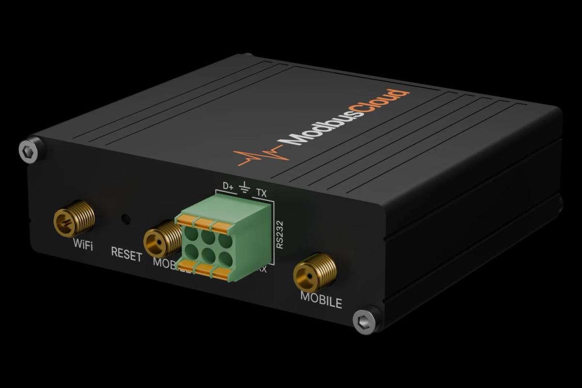
Connect port A of the central control unit (pin 6 A, pin 3 B, pin 1 or 2 GND) to RS485 A and B on the ModbusCloud Gateway, with a 120 ohm termination at the bus ends.
Use address 1 at 19200 baud, 8 data bits, no parity, 1 stop bit, unless the installer changed it.
In ModbusCloud, add the device with these settings and import this template, next to the room template if you use it.
Remove the registers of objects that are not installed, such as a second ITC, a tank or a buffer tank.
Things to watch for
Which objects does my installation have?
That depends on the hardware profile chosen at commissioning. An ITC needs the Sentio ITC module or a Calefa unit, the tank and buffer tank need their sensors. Objects that are not configured return an illegal data address or 327.67. Keep only the blocks that give real values.
Boiler and buffer tank registers give no answer.
These objects arrived in firmware package 16 (software 3.4). On older firmware they do not exist. Update the unit through the Sentio app or remove these registers.
My write to a heat curve is not accepted.
Writing needs Modbus mode read/write, or in password mode the password (default 1234) written to holding register 6 first; writes then work for 11 minutes. Values outside the range of the parameter are refused.
Why is a circuit blocked?
The blocking source register gives the reason as a code from the general list in the manual, for example dew point, outdoor temperature, cooldown period or heat source not released. Wavin notes that the list keeps growing, so a newer firmware can report a code that has no text yet.
Want to see how it works?