
WEG CFW300
Compact frequency inverter for small motors: frequency, current, faults and every drive parameter.
The WEG CFW300 is a compact frequency inverter that controls the speed of small three-phase motors in pumps, fans, conveyors and machines. This Modbus RTU template reads frequency, current, voltage, temperature and faults, and lets you write the control word, speed reference, ramps and drive parameters from ModbusCloud.
- Protocol
- Modbus RTU
- Connection
- RS485, 19200 baud
- Registers
- 330, read and write
- Brand
- WEG
- Key readings
- Output frequency · Motor current · DC link voltage · Output voltage · Module temperature · Present fault and alarm · Inverter status
- Available commands
- Run, stop and direction · Speed reference · Acceleration and deceleration time · Minimum and maximum frequency · PID setpoint
- Compatible models
- CFW300
- Last updated
Registers (330)
330 read, 258 write
| Name | Unit | Access | Address (Hidden until you enter your email) | Function (hidden) | Type (hidden) |
|---|---|---|---|---|---|
| Output Frequency (Motor) | Hz | Read | 5 | FC03 | uint16 |
| Motor Current | A | Read | 3 | FC03 | uint16 |
| DC Link Voltage | V | Read | 4 | FC03 | uint16 |
| Output Voltage | V | Read | 7 | FC03 | uint16 |
| Output Speed (Motor) | Read | 2 | FC03 | uint16 | |
| Speed Reference | Read | ||||
| Motor Torque | % | Read | |||
| Power Factor | Read | ||||
| Inverter Status | Read | ||||
| Module Temperature | °C | Read | |||
| Motor Overload Ixt | % | Read | |||
| Present Alarm | Read | ||||
| Present Fault | Read | ||||
| Logical Status | Read | ||||
| 13-Bit Speed | Read | ||||
| Serial/USB Control | Read and write | ||||
| Serial/USB Speed Ref. | Read and write | ||||
| Access to Parameters | Read and write | ||||
| DI8 to DI1 Status | Read | ||||
| DO4 to DO1 Status | Read | ||||
| AO1 Value | % | Read | |||
| AO2 Value | % | Read | |||
| AI1 Value | % | Read | |||
| AI2 Value | % | Read | |||
| Potentiometer Signal Value | % | Read | |||
| FI Value in Hz | Hz | Read | |||
| Main SW Version | Read | ||||
| IO Acces. SW Version | Read | ||||
| Comm. Acces. SW Version | Read | ||||
| Config. Acces. IO | Read | ||||
| Config. Comm. Acces. | Read | ||||
| Power HW Configuration | Read | ||||
| Encoder Speed | rpm | Read | |||
| Encoder Pulses Count | Read | ||||
| Fan Enabled Time | Read | ||||
| CONF Status | Read | ||||
| Last Fault | Read | ||||
| Current At Last Fault | A | Read | |||
| DC Link At Last Fault | V | Read | |||
| Frequency At Last Fault | Hz | Read | |||
| Temperature Last Fault | °C | Read | |||
| Second Fault | Read | ||||
| Third Fault | Read | ||||
| Last Fault on Fire Mode | Read | ||||
| Second Fault on Fire Mode | Read | ||||
| Third Fault on Fire Mode | Read | ||||
| Acceleration Time | s | Read and write | |||
| Deceleration Time | s | Read and write | |||
| Acceleration Time 2nd Ramp | s | Read and write | |||
| Deceleration Time 2nd Ramp | s | Read and write | |||
| Ramp S | Read and write | ||||
| 1st / 2nd Ramp Selection | Read and write | ||||
| Emer. R. Acceleration Time | s | Read and write | |||
| Emer. R. Time Deceleration | s | Read and write | |||
| Speed Ref. Backup | Read and write | ||||
| Reference via HMI | Hz | Read and write | |||
| JOG Reference | Hz | Read and write | |||
| Multispeed Ref. 1 | Hz | Read and write | |||
| Multispeed Ref. 2 | Hz | Read and write | |||
| Multispeed Ref. 3 | Hz | Read and write | |||
| Multispeed Ref. 4 | Hz | Read and write | |||
| Multispeed Ref. 5 | Hz | Read and write | |||
| Multispeed Ref. 6 | Hz | Read and write | |||
| Multispeed Ref. 7 | Hz | Read and write | |||
| Multispeed Ref. 8 | Hz | Read and write | |||
| Minimum Frequency | Hz | Read and write | |||
| Maximum Frequency | Hz | Read and write | |||
| Maximum Output Current | A | Read and write | |||
| Manual Torque Boost | % | Read and write | |||
| Automatic Torque Boost | % | Read and write | |||
| Slip Compensation | % | Read and write | |||
| Output Current Filter | s | Read and write | |||
| Slip Com. Filter | s | Read and write | |||
| Maximum Output Voltage | % | Read and write | |||
| Intermediate Output Voltage | % | Read and write | |||
| Field Weakening Speed | Hz | Read and write | |||
| Intermediate Frequency | Hz | Read and write | |||
| DC Link Comp. Mode | Read and write | ||||
| DC/LC Regul. Type | Read and write | ||||
| DC Link Regul. Level | V | Read and write | |||
| Dynamic Braking Level | V | Read and write | |||
| Rated Speed Overload Current | A | Read and write | |||
| Overl.Curr.50 % Speed | A | Read and write | |||
| Overl.Curr.20 % Speed | A | Read and write | |||
| Rated Flux | % | Read and write | |||
| Clear Enc. Pulse Counter | Read and write | ||||
| Password | Read and write | ||||
| Type of Control | Read and write | ||||
| Load/Save Parameters | Read and write | ||||
| Main Display Parameter | Read and write | ||||
| Bar Graph Parameter | Read and write | ||||
| Ref. Scale Factor | Read and write | ||||
| Ref. Eng. Unit | Read and write | ||||
| Ref. Decimal Point | Read and write | ||||
| Bar Scale Factor | Read and write | ||||
| Red. Switch. Freq. | Hz | Read and write | |||
| LOC/REM Selection Source | Read and write | ||||
| LOC Reference Sel. | Read and write | ||||
| REM Reference Selection | Read and write | ||||
| LOC FWD/REV Selection | Read and write | ||||
| LOC Run/Stop Sel. | Read and write | ||||
| LOC JOG Selection | Read and write | ||||
| REM FWD/REV Selection | Read and write | ||||
| REM Run/Stop Selection | Read and write | ||||
| REM JOG Selection | Read and write | ||||
| Stop Mode Selection | Read and write | ||||
| Dead Zone (AIs and FI1 ) | Read and write | ||||
| AI1 Signal Function | Read and write | ||||
| AI1 Input Gain | Read and write | ||||
| AI1 Input Signal | Read and write | ||||
| AI1 Input Offset | % | Read and write | |||
| AI1 Input Filter | s | Read and write | |||
| AI2 Signal Function | Read and write | ||||
| AI2 Input Gain | Read and write | ||||
| AI2 Input Signal | Read and write | ||||
| AI2 Input Offset | % | Read and write | |||
| AI2 Input Filter | s | Read and write | |||
| Potentiometer Signal Function | Read and write | ||||
| Potentiometer Signal Gain | Read and write | ||||
| Potentiometer Signal Offset | % | Read and write | |||
| Potentiometer and FI1 Filter | s | Read and write | |||
| FI1 Input Function | Read and write | ||||
| FI1 Input Gain | Read and write | ||||
| FI1 Minimum Input | Hz | Read and write | |||
| FI1 Input Offset | % | Read and write | |||
| FI1 Maximum Input | Hz | Read and write | |||
| AO1 Output Function | Read and write | ||||
| AO1 Output Gain | Read and write | ||||
| AO1 Output Signal | Read and write | ||||
| AO2 Output Function | Read and write | ||||
| AO2 Output Gain | Read and write | ||||
| AO2 Output Signal | Read and write | ||||
| DI1 Input Function | Read and write | ||||
| DI2 Input Function | Read and write | ||||
| DI3 Input Function | Read and write | ||||
| DI4 Input Function | Read and write | ||||
| DI5 Input Function | Read and write | ||||
| DI6 Input Function | Read and write | ||||
| DI7 Input Function | Read and write | ||||
| DI8 Input Function | Read and write | ||||
| DIs Function | Read and write | ||||
| DO1 Function | Read and write | ||||
| DO2 Function | Read and write | ||||
| DO3 Function | Read and write | ||||
| DO4 Function | Read and write | ||||
| Fx Frequency | Hz | Read and write | |||
| Fx Hysteresis | Hz | Read and write | |||
| Ix Current | A | Read and write | |||
| Tx Torque | % | Read and write | |||
| Inverter Rated Current | A | Read | |||
| Line Rated Voltage | Read and write | ||||
| Switching Frequency | Read and write | ||||
| DC Braking Start Time | s | Read and write | |||
| DC Braking Stop Time | s | Read and write | |||
| DC Braking Frequency | Hz | Read and write | |||
| DC Braking Current | % | Read and write | |||
| Skip Frequency 1 | Hz | Read and write | |||
| Skip Frequency 2 | Hz | Read and write | |||
| Skip Band | Hz | Read and write | |||
| Serial Address | Read and write | ||||
| Serial Baud Rate | Read and write | ||||
| Serial Bytes Config. | Read and write | ||||
| Serial Protocol | Read and write | ||||
| Action for Communic. Error | Read and write | ||||
| Serial Watchdog | s | Read and write | |||
| Serial Interf. Status | Read | ||||
| Flying Start / Ride-Through | Read and write | ||||
| Voltage Ramp for FS and RT | s | Read and write | |||
| Dead Time | s | Read and write | |||
| Auto-Reset Time | s | Read and write | |||
| Fan Control Config. | Read and write | ||||
| Encoder Fault Config. | Read and write | ||||
| External Sensor Temp. | °C | Read | |||
| Control Config | Read and write | ||||
| Motor Rated Efficiency | % | Read and write | |||
| Motor Rated Voltage | V | Read and write | |||
| Motor Rated Current | A | Read and write | |||
| Motor Rated Speed | rpm | Read and write | |||
| Motor Rated Frequency | Hz | Read and write | |||
| Motor Rated Power | Read and write | ||||
| Encoder Pulses Number | Read and write | ||||
| Motor Rated Power Factor | Read and write | ||||
| Run Self-Tuning | Read and write | ||||
| Stator Resistance | Read and write | ||||
| SoftPLC Eng. Unit | Read and write | ||||
| SoftPLC Indication Form | Read and write | ||||
| Fire Mode Configuration | Read and write | ||||
| Fire Mode Auto-reset Adjustable | Read and write | ||||
| EOC Maximum Torque | % | Read and write | |||
| EOC Minimum Voltage | % | Read and write | |||
| EOC Minimum Frequency | Hz | Read and write | |||
| EOC Hysteresis | % | Read and write | |||
| Main SW Revision | Read | ||||
| CO/DN/DP/ETH Control | Read | ||||
| CO/DN/DP/ETH Speed Ref | Read | ||||
| Logic State 2 | Read | ||||
| DOx Value | Read | ||||
| AOx Value 1 | Read | ||||
| AOx Value 2 | Read | ||||
| CAN Protocol | Read and write | ||||
| CAN Address | Read and write | ||||
| CAN Baud Rate | Read and write | ||||
| Bus Off Reset | Read and write | ||||
| CAN Controller Status | Read | ||||
| RX CAN Telegrams | Read | ||||
| TX CAN Telegrams | Read | ||||
| Bus Off Counter | Read | ||||
| CAN Lost Messages | Read | ||||
| DeviceNet I/O instances | Read and write | ||||
| DeviceNet Read Word #3 | Read and write | ||||
| DeviceNet Read Word #4 | Read and write | ||||
| DeviceNet Read Word #5 | Read and write | ||||
| DeviceNet Read Word #6 | Read and write | ||||
| DeviceNet Write Word #3 | Read and write | ||||
| DeviceNet Write Word #4 | Read and write | ||||
| DeviceNet Write Word #5 | Read and write | ||||
| DeviceNet Write Word #6 | Read and write | ||||
| DeviceNet Network Status | Read | ||||
| DeviceNet Master Status | Read | ||||
| CANopen Comm. Status | Read | ||||
| CANopen Node Status | Read | ||||
| Profibus Comm. Status | Read | ||||
| Profibus Read Word #3 | Read and write | ||||
| Profibus Read Word #4 | Read and write | ||||
| Profibus Read Word #5 | Read and write | ||||
| Profibus Read Word #6 | Read and write | ||||
| Profibus Write Word#3 | Read and write | ||||
| Profibus Write Word#4 | Read and write | ||||
| Profibus Write Word#5 | Read and write | ||||
| Profibus Write Word#6 | Read and write | ||||
| Profibus Address | Read and write | ||||
| Profibus Teleg. Sel. | Read and write | ||||
| Profibus Baud Rate | Read and write | ||||
| BACnet Dev Inst Hi | Read and write | ||||
| BACnet Dev Inst Lo | Read and write | ||||
| Max Number of master | Read and write | ||||
| MS/TP Max info Frame | Read and write | ||||
| I-AM Msg transmition | Read and write | ||||
| Token RX Quantity | Read | ||||
| Blueooth Device Name | Read and write | ||||
| Bluetooth Password PIN | Read and write | ||||
| IR Control Command | Read | ||||
| IR Controle Selection | Read and write | ||||
| Quick View 1 IR | Read and write | ||||
| Quick View 2 IR | Read and write | ||||
| IP Address Config | Read and write | ||||
| IP Address 1 | Read and write | ||||
| IP Address 2 | Read and write | ||||
| IP Address 3 | Read and write | ||||
| IP Address 4 | Read and write | ||||
| CIDR Sub-net | Read and write | ||||
| Gateway 1 | Read and write | ||||
| Gateway 2 | Read and write | ||||
| Gateway 3 | Read and write | ||||
| Gateway 4 | Read and write | ||||
| MBTCP: Communication Status | Read | ||||
| MBTCP: Active Connections | Read | ||||
| MBTCP: TCP Port | Read and write | ||||
| MBTCP: Timeout | s | Read and write | |||
| EIP: Master Status | Read | ||||
| EIP: Communication Status | Read | ||||
| EIP: Data Profile | Read and write | ||||
| Ethernet Read Word #3 | Read and write | ||||
| Ethernet Read Word #4 | Read and write | ||||
| Ethernet Read Word #5 | Read and write | ||||
| Ethernet Read Word #6 | Read and write | ||||
| Ethernet Read Word #7 | Read and write | ||||
| Ethernet Read Word #8 | Read and write | ||||
| Ethernet Write Word #3 | Read and write | ||||
| Ethernet Write Word #4 | Read and write | ||||
| Ethernet Write Word #5 | Read and write | ||||
| Ethernet Write Word #6 | Read and write | ||||
| Ethernet Write Word #7 | Read and write | ||||
| Ethernet Write Word #8 | Read and write | ||||
| Ethernet Interface Status | Read | ||||
| SoftPLC Status | Read | ||||
| SoftPLC Command | Read and write | ||||
| Scan Cycle Time | s | Read | |||
| SoftPLC Appl. | Read and write | ||||
| Action for SoftPLC Application not Running | Read and write | ||||
| SoftPLC Parameter 1 | Read and write | ||||
| SoftPLC Parameter 2 | Read and write | ||||
| SoftPLC Parameter 3 | Read and write | ||||
| SoftPLC Parameter 4 | Read and write | ||||
| SoftPLC Parameter 5 | Read and write | ||||
| SoftPLC Parameter 6 | Read and write | ||||
| SoftPLC Parameter 7 | Read and write | ||||
| SoftPLC Parameter 8 | Read and write | ||||
| SoftPLC Parameter 9 | Read and write | ||||
| SoftPLC Parameter 10 | Read and write | ||||
| SoftPLC Parameter 11 | Read and write | ||||
| SoftPLC Parameter 12 | Read and write | ||||
| SoftPLC Parameter 13 | Read and write | ||||
| SoftPLC Parameter 14 | Read and write | ||||
| SoftPLC Parameter 15 | Read and write | ||||
| SoftPLC Parameter 16 | Read and write | ||||
| SoftPLC Parameter 17 | Read and write | ||||
| SoftPLC Parameter 18 | Read and write | ||||
| SoftPLC Parameter 19 | Read and write | ||||
| SoftPLC Parameter 20 | Read and write | ||||
| SoftPLC Parameter 21 | Read and write | ||||
| SoftPLC Parameter 22 | Read and write | ||||
| SoftPLC Parameter 23 | Read and write | ||||
| SoftPLC Parameter 24 | Read and write | ||||
| SoftPLC Parameter 25 | Read and write | ||||
| SoftPLC Parameter 26 | Read and write | ||||
| SoftPLC Parameter 27 | Read and write | ||||
| SoftPLC Parameter 28 | Read and write | ||||
| SoftPLC Parameter 29 | Read and write | ||||
| SoftPLC Parameter 30 | Read and write | ||||
| SoftPLC Parameter 31 | Read and write | ||||
| SoftPLC Parameter 32 | Read and write | ||||
| SoftPLC Parameter 33 | Read and write | ||||
| SoftPLC Parameter 34 | Read and write | ||||
| SoftPLC Parameter 35 | Read and write | ||||
| SoftPLC Parameter 36 | Read and write | ||||
| SoftPLC Parameter 37 | Read and write | ||||
| SoftPLC Parameter 38 | Read and write | ||||
| SoftPLC Parameter 39 | Read and write | ||||
| SoftPLC Parameter 40 | Read and write | ||||
| SoftPLC Parameter 41 | Read and write | ||||
| SoftPLC Parameter 42 | Read and write | ||||
| SoftPLC Parameter 43 | Read and write | ||||
| SoftPLC Parameter 44 | Read and write | ||||
| SoftPLC Parameter 45 | Read and write | ||||
| SoftPLC Parameter 46 | Read and write | ||||
| SoftPLC Parameter 47 | Read and write | ||||
| SoftPLC Parameter 48 | Read and write | ||||
| SoftPLC Parameter 49 | Read and write | ||||
| SoftPLC Parameter 50 | Read and write |
Loading registers…
Send your device list
If a device is not in the library yet, we build the template for free as soon as we have the register data.
Use cases
- Show output frequency, motor current and DC link voltage of every drive on one dashboard.
- Send an alarm when the present fault code is not zero or the module temperature passes a threshold.
- Keep a year of current history to see when a pump or fan starts to run heavier.
- Change the speed reference or the PID control setpoint of a small pump from ModbusCloud.
- Compare motor overload and fan running time across drives to plan maintenance.
Installation
Fit the CFW300-CRS485 module and connect terminal 25 (A) and terminal 26 (B) to RS485 A and B of the ModbusCloud Gateway. Turn S1.1 and S1.2 on at the last device on the bus.
On the drive set P308 to the Modbus address, P310 to the baud rate, P311 to the byte format and P312 to 2 (Modbus RTU Slave).
If ModbusCloud should control the drive, set the command and reference sources in P220 to P228 to Serial/USB.
In ModbusCloud add a Modbus device on the Gateway with the same address and serial settings and import this template.
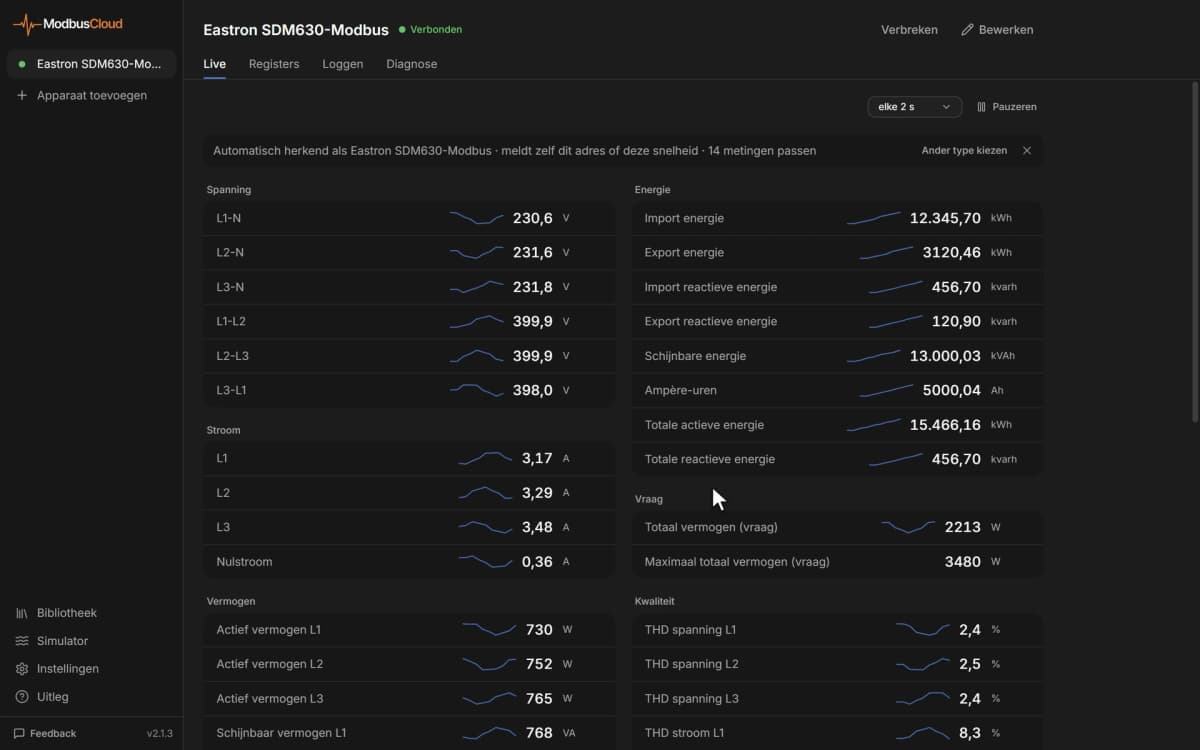
Check that Output Frequency, Motor Current and DC Link Voltage show plausible values with the drive powered.
Things to watch for
The drive does not answer on the bus. What should I check?
Check that the CFW300-CRS485 module is fitted and P316 shows the interface as active. Address, baud rate and byte format in P308, P310 and P311 must match ModbusCloud; the defaults are address 1, 19200 baud, 8 data bits, even parity, 1 stop bit. If it stays silent, swap A and B and check the termination switches.
Why do current and frequency show ten times the real value?
The drive sends whole numbers without the decimal point, so 3.5 A arrives as 35 and 50.0 Hz as 500. The template applies the scale from the parameter list. If a value is still off, compare it with the keypad reading and check the firmware version in P023.
How do I start the motor and set the speed?
Set the command and reference sources (P220 to P228) to Serial/USB. Write the speed reference, where 8192 equals the rated motor frequency, and the serial control word with bit 0 (ramp enable), bit 1 (general enable) and bit 4 (remote) set. Test with the motor uncoupled first.
Some parameters refuse a write. Why?
Configuration parameters can only be changed with the motor stopped, and read only parameters never accept a write. Values outside the range in the comment are rejected as well. Change one setting at a time and read it back to confirm.
What do the parameters from P910 to P939 mean?
They are SoftPLC parameters. With the PID Controller application active (P903 = 1) they hold the control setpoints, process variable, PID gains and sleep mode settings; the comment of each register gives that meaning.
More WEG templates

Want to see how it works?