On this page
RS485 is the physical layer that Modbus RTU runs on. Most "Modbus isn't working" problems are actually RS485 wiring problems: swapped A/B polarity, missing termination, wrong cable type, or shield grounded at both ends. This article covers the complete technical foundation plus the practical installation procedure for a reliable Modbus RTU setup in HVAC, solar PV, and building automation.
The TIA/EIA-485-A standard in brief
RS485 is defined in ANSI/TIA/EIA-485-A-1998 (originally published April 1983, reaffirmed 2012). The standard specifies only the electrical characteristics of drivers and receivers - it does not define the protocol, connectors, or cable. Those come from Modbus, Profibus, and BACnet specifications.
| Parameter | Value |
|---|---|
| Signal type | Differential (A and B) |
| Driver output (loaded) | Min ±1.5V across 54Ω |
| Receiver sensitivity | ±200mV differential |
| Common-mode range | −7V to +12V |
| Max devices (standard UL) | 32 |
| Max devices (1/8 UL) | 256 |
| Max cable length | 1200m at 9600 baud |
| Rule of thumb | baud rate × length ≤ 10^8 |
Data is encoded as the difference between V_A and V_B. Noise couples equally into both wires and is rejected by the differential receiver - which is why RS485 works reliably over 1200m while RS232 fails after 15m.
Cable selection
The correct cable is shielded twisted pair with 120Ω characteristic impedance. This is why Cat5/6 often works but isn't ideal - its impedance is 100Ω.
| Cable | Impedance | AWG | Capacitance | Application |
|---|---|---|---|---|
| Belden 9841 | 120Ω | 24 | 42 pF/m | Standard RS485, indoor |
| Belden 9842 | 120Ω | 24 (2 pair) | 42 pF/m | Full-duplex or extra GND |
| Belden 3105A | 120Ω | 22 | 36 pF/m | Industrial, outdoor |
| Lapp Unitronic BUS LD | 120Ω | 24 | ~42 pF/m | Profibus/Modbus, EU market |
| Cat5e / Cat6 | ~100Ω | 24 | 50-55 pF/m | Acceptable <600m, low baud |
Maximum length by baud rate:
| Baud rate | Max length | Notes |
|---|---|---|
| 9,600 bps | 1200m | Well within rule of thumb |
| 19,200 bps | 1200m | Timing margins tighter |
| 38,400 bps | ~1200m | Marginal at full length |
| 115,200 bps | ~500m | Per Chipkin |
| 10 Mbps | ~12m | Per Analog Devices |
Topology: why only daisy-chain works
RS485 must be wired as a daisy-chain (linear bus). The cable runs from one end of the bus to the other, tapping briefly at each device's terminals.
Star topology fails because each branch introduces an impedance discontinuity where signals reflect. Texas Instruments (SNLA042A): "Star configurations are discouraged-the device is effectively at the end of a very long stub."
Keep stubs <1m at any baud rate above 9600. For Profibus: 6.6m at 93.75 kbit/s, but 0m at >1.5 Mbit/s. Ring topology is not supported.
If the building layout doesn't allow a daisy-chain, use RS485 repeaters (active hubs). Each creates a new segment with its own termination.
Termination: 120Ω at both ends
When cable length exceeds ~1/10 of the signal wavelength, an unterminated end reflects the signal back - producing CRC errors. The fix: a 120Ω ¼W resistor between A and B at both physical ends of the bus.
| Symptom | Cause |
|---|---|
| CRC errors at distance, works nearby | Missing termination |
| Weak signals, reduced swing | Double/triple termination |
| Random CRC at high baud | Termination on stubs/wrong location |
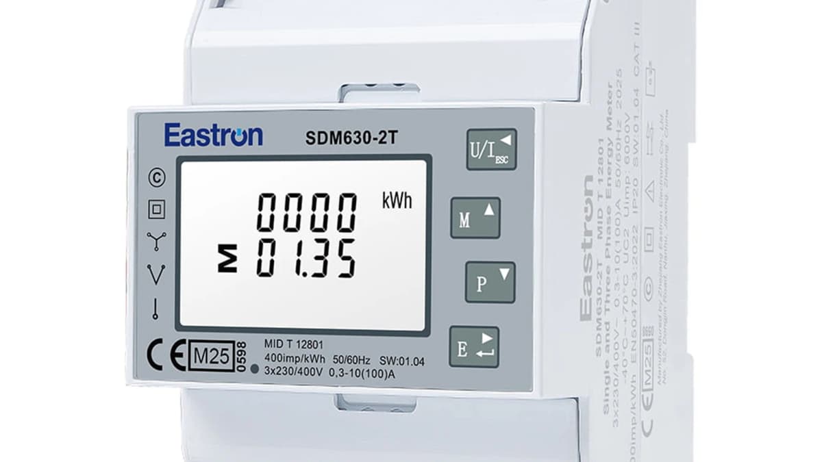
Many devices (Eastron SDM630, Siemens Sentron, some gateways) have a DIP switch or jumper for built-in termination. Always check the manual before adding external resistors.
A/B polarity: the number one problem
The TIA-485-A standard states: A = inverting (low during idle), B = non-inverting (high during idle). During idle, B is positive relative to A.
IC manufacturers (TI, Maxim, Analog Devices, FTDI) all follow this convention. But equipment manufacturers don't:
| Source | Positive (high in idle) | Negative (low in idle) |
|---|---|---|
| TIA-485-A standard | B | A |
| TI / Maxim / ADI ICs | B | A |
| Modbus specification | D1 | D0 |
| BACnet (ASHRAE 135) | + | − |
| Profibus | B (red wire) | A (green wire) |
| Many PLCs and meters | varies | varies |
Siemens explicitly warns that A/B labels are not standardized across manufacturers.
Practical solution: ignore the letters. Connect + to + and − to −. Measure idle DC voltage with a multimeter - the wire with the higher voltage is the positive signal (B/D+). No communication? Swap the two data wires. This won't damage any hardware.
Wiring step by step
- 1
Plan the route
Map all device locations. Design a strict daisy-chain. Place the master/gateway at one end. Keep stub lengths <0.3m. Route cables at least 100mm from power cables (per EN 50174-2). Cross power cables only at 90°.
- 2
Select and measure cable
Belden 9841 for standard indoor, Cat5e for short runs, Belden 3105A for industrial/outdoor. Add 10-15% extra for routing. Never use non-twisted cable or standard installation wire - it provides no noise rejection.
- 3
Prepare the cable ends
Strip 50mm outer jacket. Strip 8mm per conductor. Wire ferrules are mandatory - bare stranded wire produces intermittent contact faults (extensively documented in the Teltonika community). Keep the twisted pair twisted as close to the terminal as possible.
- 4
Wire the master/gateway first
Cable the gateway (e.g. ModbusCloud Gateway or Teltonika TRB246) and configure serial parameters (in the ModbusCloud portal, or via the web interface of a stand-alone gateway). For the TRB246: bridge R+ to D+ and R− to D− for half-duplex (standard Modbus RTU). Power on and verify boot.
- 5
Daisy-chain to each subsequent device
At each device, two cables land: one incoming, one outgoing. Both on the same terminals (A to A, B to B). Maximum 2 wires per terminal - this forces daisy-chain discipline. Set a unique Modbus address (1-247) plus identical baud/parity on every device.
- 6
Install 120Ω termination
At the first device (gateway) and the last device. Never in the middle. Check for built-in DIP switches first. External: 120Ω ¼W resistor between A and B.
- 7
Ground shield at one end only
Connect the drain wire/braid to earth only at the master side. At the far end, leave the shield floating and insulated. Grounding both ends creates a ground loop that injects noise.
- 8
Test per device
Test each device individually with an FTDI USB-RS485 adapter and QModMaster or Modbus Poll before connecting the next one. This localizes faults early.
Grounding and shielding
The signal ground wire (the third wire, alongside A and B) is mandatory. Control Solutions Minnesota calls missing ground "the #1 cause of RS485 failures". Without a common ground reference, the common-mode difference between devices can exceed the −7V/+12V range - resulting in CRC errors and, in severe cases, hardware damage.
The shield (braid/foil) is grounded at one end only - by convention, the master side. Daisy-chain the shield electrically through between devices (all drain wires connected) but earth it only once.
Fail-safe biasing
When no driver is active (bus in idle), the termination resistors pull the differential voltage to 0V - an undefined state that can produce "false start bits". Bias resistors prevent this:
| Resistor | Connection | Typical value |
|---|---|---|
| Pull-up | B/D+ to Vcc (5V/3.3V) | 560Ω or 680Ω |
| Pull-down | A/D− to GND | 560Ω or 680Ω |
Install biasing at one location only (typically the master). Modern "True Fail-Safe" transceivers (MAX3080, ISL83082) have a −50mV threshold and don't need external biasing - but older equipment often does.
Top 10 wiring mistakes
- Star topology - Causes reflections and random CRC errors. Use daisy-chain, or repeaters.
- A/B swapped - Problem #1 at commissioning. Swap the wires. Won't damage anything.
- Missing or wrong termination - 120Ω only at both physical ends, never in the middle.
- No GND wire - #1 root cause per Control Solutions.
- Shield grounded at both ends - Creates ground loop, injects noise into the signal.
- RS485 parallel to power cables - EMC problem. Keep 100mm+ away, cross at 90°.
- Wrong cable type - Non-twisted, standard installation wire, or wrong impedance.
- Too many devices - Above 32 unit loads without a repeater.
- Stubs too long - Keep <1m. Long branches cause reflections.
- Settings not identical - Baud rate, parity, stop bits, data bits must match exactly on every device.
Troubleshooting with a multimeter
| Test | Reading | Conclusion |
|---|---|---|
| DC voltage A vs B (idle) | B is 200mV-5V higher than A | Normal |
| DC voltage A vs B (idle) | ~0V | Bus undefined - add biasing |
| DC voltage A vs B (idle) | A higher than B | Polarity reversed |
| Resistance A-B (power off) | ~60Ω | Two terminators - correct |
| Resistance A-B (power off) | ~120Ω | One terminator - one end missing |
| Resistance A-B (power off) | OL (open) | No termination |
| Resistance A-B (power off) | <10Ω | Short circuit - cable fault |
| Common-mode GND-GND | <1V | Acceptable |
| Common-mode GND-GND | 1-7V | Marginal |
| Common-mode GND-GND | >7V | Isolated repeater required |
Software tools: QModMaster (free, open-source) or Modbus Poll (commercial, 30-day trial). Use an FTDI-based USB-RS485 adapter - avoid cheap CH340 chips, which cause timing issues and echo problems.
Regulations and standards
TIA-485-A defines the physical layer (April 1983, revised 1998, reaffirmed 2012). TSB-89A provides application guidance including the baud × length ≤ 10^8 rule.
EN 50174-2 governs data cabling installation inside buildings in Europe. Key requirements:
- Separation distances between data and power cables
- EMC-compatible grounding and equipotential bonding
- Cable management system requirements
EN 50575 (CPR) - since July 2017, all permanently installed cables in EU buildings must meet CPR requirements with CE marking and a Declaration of Performance. RS485 cables typically fall in classes B2ca to Eca depending on building type.
Modbus Serial Line Specification V1.02 (modbus.org, December 2006) standardizes Modbus RTU over RS485: TIA/EIA-485 two-wire, master-slave (1 master + up to 247 slaves), default 19200 bps, 8 data bits, even parity, 1 stop bit (though 9600-8N1 is far more common in practice).
Frequently asked questions
What's the difference between RS485 and Modbus?
RS485 is the physical layer (hardware, voltage levels, cable). Modbus RTU is the protocol running on top (message format, CRC, slave addressing). You need both: RS485 without Modbus is just a serial wire with no meaning, Modbus without RS485 only works over TCP/IP.
How many devices can I connect to one bus?
32 unit loads per segment is the standard. With 1/8 UL transceivers (e.g., MAX3485), up to 256. Modbus addressing allows 1-247. Above 32 devices: use an RS485 repeater to segment the bus.
Can I use Cat5 or Cat6 cable?
Yes, in most cases this works fine. The impedance is 100Ω instead of 120Ω, but for baud rates up to 38400 and lengths up to 600m this rarely causes problems. Use one twisted pair for A/B and a wire from another pair for GND.
When do I need termination resistors?
Always at both physical ends of the bus for lengths >50m or baud rates >19200. For short buses (<10m) at 9600 baud it's often optional, but in production installations it's best practice to always terminate. 120Ω ¼W between A and B.
My Modbus isn't working. Where do I start?
Systematically: 1) measure idle voltage A vs B (B should be higher - if not, swap wires), 2) check baud rate/parity/stop bits are identical, 3) check slave address is unique, 4) verify GND wire is continuous, 5) confirm 120Ω termination at both ends, 6) ensure no second master on the bus.
How should I connect the cable shield?
At ONE end only (master/gateway side). At the far end, leave it floating and insulated. Grounding both ends creates a ground loop that injects noise into the signal. Do carry the shield electrically through between devices.
Can I wire RS485 in a star topology?
Not recommended. Standard RS485 requires a linear bus. At low baud rates and short distances (<50m), a star sometimes works in practice, but with CRC errors. Use an RS485 repeater/hub if you genuinely need a star layout.
Why am I getting CRC errors?
Most common causes (in order): 1) missing termination, 2) stubs too long, 3) no GND wire, 4) EMI from nearby VFDs or switching supplies, 5) shield grounded at both ends, 6) poor USB adapter (CH340 instead of FTDI), 7) baud rate mismatch.
Conclusion
A reliable RS485 installation is mostly a matter of discipline: daisy-chain topology, correct 120Ω termination at both ends, common ground, shield grounded at one end only. Follow these four rules and Modbus RTU works on the first attempt.
With the right cable (Belden 9841 or equivalent), wire ferrules, and a decent FTDI-based test adapter, you can install a 32-device bus over 1200m without a single CRC error. Most installation problems don't come from hardware - they come from shortcuts that ignore the physics.
Once the bus is wired, the ModbusCloud Gateway reads your Modbus RTU and TCP devices into a cloud dashboard using ready-made templates for common meters and controllers.