

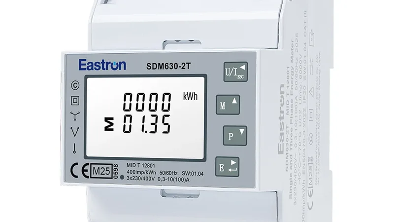

Accuenergy Acuvim II Class S Power Quality
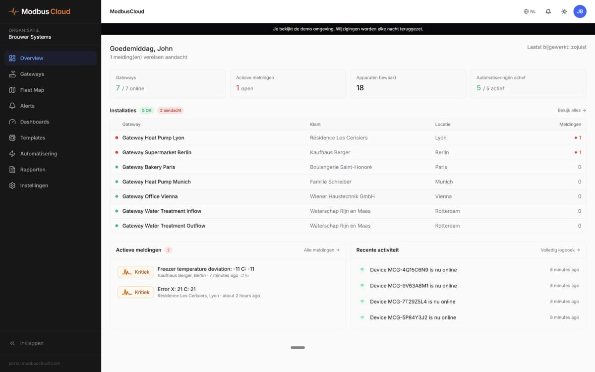
Power quality meter values aggregated over 200 ms to 2 h, with sag, swell and unbalance event settings.
The Accuenergy Acuvim II is a power meter that measures energy and power quality in low-voltage switchboards, with Class S power quality events on the Acuvim IIW. This Modbus RTU template reads aggregated voltage, current, THD and unbalance over 200 ms to 2 h and lets you set sag, swell, interruption and unbalance detection from ModbusCloud.
- Protocol
- Modbus RTU
- Connection
- RS485, 19200 baud
- Registers
- 232, read and write
- Brand
- Accuenergy
- Key readings
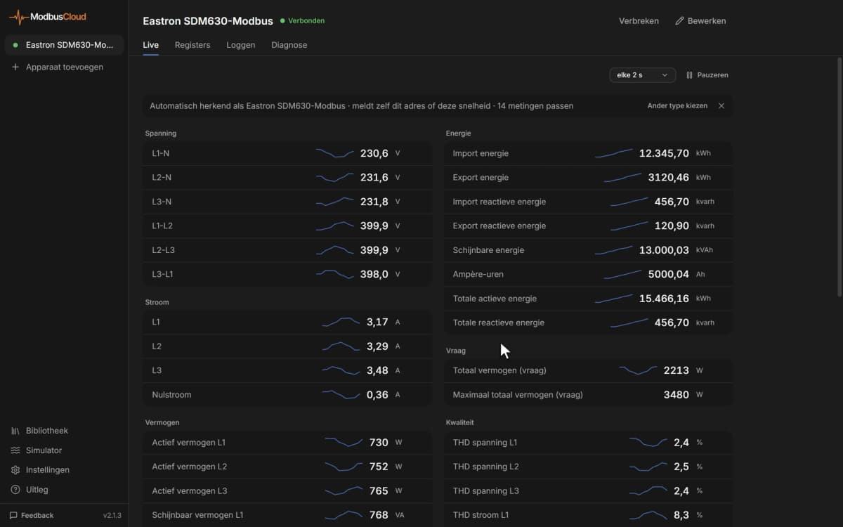
- Frequency · Phase and line voltage · Phase current · Voltage and current THD · Voltage unbalance · Sequence components
- Available commands
- Class S event enable · Rated voltage and current · Sag and swell threshold · Interruption threshold · Unbalance threshold · Event output action
- Compatible models
- Acuvim IIW · Accuenergy Acuvim II series with Class S power quality events
- Last updated
Registers (232)
232 read, 40 write
| Name | Unit | Access | Address (Hidden until you enter your email) | Function (hidden) | Type (hidden) |
|---|---|---|---|---|---|
| Class S PQ Event Enable | Read and write | 44901 | FC03 / FC16 | uint16 | |
| Rated Voltage | V | Read and write | 44902 | FC03 / FC16 | uint16 |
| Rated Current | Read and write | 44903 | FC03 / FC16 | uint16 | |
| Sampling Rate | Read and write | 44904 | FC03 / FC16 | uint16 | |
| Voltage Sag Enable | Read and write | 44905 | FC03 / FC16 | uint16 | |
| Voltage Sag Threshold | % | Read and write | |||
| Voltage Sag Hysteresis | % | Read and write | |||
| Voltage Sag Waveform Trigger | Read and write | ||||
| Voltage Sag DO Enable | Read and write | ||||
| Voltage Sag RO Enable | Read and write | ||||
| Voltage Swell Enable | Read and write | ||||
| Voltage Swell Threshold | % | Read and write | |||
| Voltage Swell Hysteresis | % | Read and write | |||
| Voltage Swell Waveform Trigger | Read and write | ||||
| Voltage Swell DO Enable | Read and write | ||||
| Voltage Swell RO Enable | Read and write | ||||
| Voltage Interrupt Enable | Read and write | ||||
| Voltage Interrupt Threshold | % | Read and write | |||
| Voltage Interrupt Hysteresis | % | Read and write | |||
| Voltage Interrupt Waveform Trigger | Read and write | ||||
| Voltage Interrupt DO Enable | Read and write | ||||
| Voltage Interrupt RO Enable | Read and write | ||||
| Unbalance Voltage Enable | Read and write | ||||
| Unbalance Voltage Threshold | % | Read and write | |||
| Unbalance Voltage Hysteresis | % | Read and write | |||
| Unbalance Voltage Waveform Trigger | Read and write | ||||
| Unbalance Voltage DO Enable | Read and write | ||||
| Unbalance Voltage RO Enable | Read and write | ||||
| Current Swell Enable | Read and write | ||||
| Current Swell Threshold | % | Read and write | |||
| Current Swell Hysteresis | % | Read and write | |||
| Current Swell Waveform Trigger | Read and write | ||||
| Current Swell DO Enable | Read and write | ||||
| Current Swell RO Enable | Read and write | ||||
| Unbalance Current Enable | Read and write | ||||
| Unbalance Current Threshold | % | Read and write | |||
| Unbalance Current Hysteresis | % | Read and write | |||
| Unbalance Current Waveform Trigger | Read and write | ||||
| Unbalance Current DO Enable | Read and write | ||||
| Unbalance Current RO Enable | Read and write | ||||
| Frequency 200 ms | Hz | Read | |||
| Phase A Line-Neutral Voltage 200 ms | V | Read | |||
| Phase B Line-Neutral Voltage 200 ms | V | Read | |||
| Phase C Line-Neutral Voltage 200 ms | V | Read | |||
| Line Voltage AB 200 ms | V | Read | |||
| Line Voltage BC 200 ms | V | Read | |||
| Line Voltage CA 200 ms | V | Read | |||
| Average Line-Neutral Voltage 200 ms | V | Read | |||
| Average Line-Line Voltage 200 ms | V | Read | |||
| Phase A Current 200 ms | A | Read | |||
| Phase B Current 200 ms | A | Read | |||
| Phase C Current 200 ms | A | Read | |||
| Neutral Current 200 ms | A | Read | |||
| Average Current 200 ms | A | Read | |||
| Phase A (AB) Voltage THD 200 ms | % | Read | |||
| Phase A (AB) Voltage ODD THD 200 ms | % | Read | |||
| Phase A (AB) Voltage EVEN THD 200 ms | % | Read | |||
| Phase B (BC) Voltage THD 200 ms | % | Read | |||
| Phase B (BC) Voltage ODD THD 200 ms | % | Read | |||
| Phase B (BC) Voltage EVEN THD 200 ms | % | Read | |||
| Phase C (CA) Voltage THD 200 ms | % | Read | |||
| Phase C (CA) Voltage ODD THD 200 ms | % | Read | |||
| Phase C (CA) Voltage EVEN THD 200 ms | % | Read | |||
| Phase A Current THD 200 ms | % | Read | |||
| Phase A Current ODD THD 200 ms | % | Read | |||
| Phase A Current EVEN THD 200 ms | % | Read | |||
| Phase B Current THD 200 ms | % | Read | |||
| Phase B Current ODD THD 200 ms | % | Read | |||
| Phase B Current EVEN THD 200 ms | % | Read | |||
| Phase C Current THD 200 ms | % | Read | |||
| Phase C Current ODD THD 200 ms | % | Read | |||
| Phase C Current EVEN THD 200 ms | % | Read | |||
| Voltage Unbalance Factor 200 ms | % | Read | |||
| Voltage Zero Unbalance Factor 200 ms | % | Read | |||
| Voltage Zero Sequence (Real) 200 ms | V | Read | |||
| Voltage Zero Sequence (Imaginary) 200 ms | V | Read | |||
| Voltage Positive Sequence (Real) 200 ms | V | Read | |||
| Voltage Positive Sequence (Imaginary) 200 ms | V | Read | |||
| Voltage Negative Sequence (Real) 200 ms | V | Read | |||
| Voltage Negative Sequence (Imaginary) 200 ms | V | Read | |||
| Current Unbalance Factor 200 ms | Read | ||||
| Current Zero Unbalance Factor 200 ms | Read | ||||
| Current Zero Sequence (Real) 200 ms | A | Read | |||
| Current Zero Sequence (Imaginary) 200 ms | A | Read | |||
| Current Positive Sequence (Real) 200 ms | A | Read | |||
| Current Positive Sequence (Imaginary) 200 ms | A | Read | |||
| Current Negative Sequence (Real) 200 ms | A | Read | |||
| Current Negative Sequence (Imaginary) 200 ms | A | Read | |||
| Frequency 3 s | Hz | Read | |||
| Phase A Line-Neutral Voltage 3 s | V | Read | |||
| Phase B Line-Neutral Voltage 3 s | V | Read | |||
| Phase C Line-Neutral Voltage 3 s | V | Read | |||
| Line Voltage AB 3 s | V | Read | |||
| Line Voltage BC 3 s | V | Read | |||
| Line Voltage CA 3 s | V | Read | |||
| Average Line-Neutral Voltage 3 s | V | Read | |||
| Average Line-Line Voltage 3 s | V | Read | |||
| Phase A Current 3 s | A | Read | |||
| Phase B Current 3 s | A | Read | |||
| Phase C Current 3 s | A | Read | |||
| Neutral Current 3 s | A | Read | |||
| Average Current 3 s | A | Read | |||
| Phase A (AB) Voltage THD 3 s | % | Read | |||
| Phase A (AB) Voltage ODD THD 3 s | % | Read | |||
| Phase A (AB) Voltage EVEN THD 3 s | % | Read | |||
| Phase B (BC) Voltage THD 3 s | % | Read | |||
| Phase B (BC) Voltage ODD THD 3 s | % | Read | |||
| Phase B (BC) Voltage EVEN THD 3 s | % | Read | |||
| Phase C (CA) Voltage THD 3 s | % | Read | |||
| Phase C (CA) Voltage ODD THD 3 s | % | Read | |||
| Phase C (CA) Voltage EVEN THD 3 s | % | Read | |||
| Phase A Current THD 3 s | % | Read | |||
| Phase A Current ODD THD 3 s | % | Read | |||
| Phase A Current EVEN THD 3 s | % | Read | |||
| Phase B Current THD 3 s | % | Read | |||
| Phase B Current ODD THD 3 s | % | Read | |||
| Phase B Current EVEN THD 3 s | % | Read | |||
| Phase C Current THD 3 s | % | Read | |||
| Phase C Current ODD THD 3 s | % | Read | |||
| Phase C Current EVEN THD 3 s | % | Read | |||
| Voltage Unbalance Factor 3 s | % | Read | |||
| Voltage Zero Unbalance Factor 3 s | % | Read | |||
| Voltage Zero Sequence (Real) 3 s | V | Read | |||
| Voltage Zero Sequence (Imaginary) 3 s | V | Read | |||
| Voltage Positive Sequence (Real) 3 s | V | Read | |||
| Voltage Positive Sequence (Imaginary) 3 s | V | Read | |||
| Voltage Negative Sequence (Real) 3 s | V | Read | |||
| Voltage Negative Sequence (Imaginary) 3 s | V | Read | |||
| Current Unbalance Factor 3 s | Read | ||||
| Current Zero Unbalance Factor 3 s | Read | ||||
| Current Zero Sequence (Real) 3 s | A | Read | |||
| Current Zero Sequence (Imaginary) 3 s | A | Read | |||
| Current Positive Sequence (Real) 3 s | A | Read | |||
| Current Positive Sequence (Imaginary) 3 s | A | Read | |||
| Current Negative Sequence (Real) 3 s | A | Read | |||
| Current Negative Sequence (Imaginary) 3 s | A | Read | |||
| Frequency 10 min | Hz | Read | |||
| Phase A Line-Neutral Voltage 10 min | V | Read | |||
| Phase B Line-Neutral Voltage 10 min | V | Read | |||
| Phase C Line-Neutral Voltage 10 min | V | Read | |||
| Line Voltage AB 10 min | V | Read | |||
| Line Voltage BC 10 min | V | Read | |||
| Line Voltage CA 10 min | V | Read | |||
| Average Line-Neutral Voltage 10 min | V | Read | |||
| Average Line-Line Voltage 10 min | V | Read | |||
| Phase A Current 10 min | A | Read | |||
| Phase B Current 10 min | A | Read | |||
| Phase C Current 10 min | A | Read | |||
| Neutral Current 10 min | A | Read | |||
| Average Current 10 min | A | Read | |||
| Phase A (AB) Voltage THD 10 min | % | Read | |||
| Phase A (AB) Voltage ODD THD 10 min | % | Read | |||
| Phase A (AB) Voltage EVEN THD 10 min | % | Read | |||
| Phase B (BC) Voltage THD 10 min | % | Read | |||
| Phase B (BC) Voltage ODD THD 10 min | % | Read | |||
| Phase B (BC) Voltage EVEN THD 10 min | % | Read | |||
| Phase C (CA) Voltage THD 10 min | % | Read | |||
| Phase C (CA) Voltage ODD THD 10 min | % | Read | |||
| Phase C (CA) Voltage EVEN THD 10 min | % | Read | |||
| Phase A Current THD 10 min | % | Read | |||
| Phase A Current ODD THD 10 min | % | Read | |||
| Phase A Current EVEN THD 10 min | % | Read | |||
| Phase B Current THD 10 min | % | Read | |||
| Phase B Current ODD THD 10 min | % | Read | |||
| Phase B Current EVEN THD 10 min | % | Read | |||
| Phase C Current THD 10 min | % | Read | |||
| Phase C Current ODD THD 10 min | % | Read | |||
| Phase C Current EVEN THD 10 min | % | Read | |||
| Voltage Unbalance Factor 10 min | % | Read | |||
| Voltage Zero Unbalance Factor 10 min | % | Read | |||
| Voltage Zero Sequence (Real) 10 min | V | Read | |||
| Voltage Zero Sequence (Imaginary) 10 min | V | Read | |||
| Voltage Positive Sequence (Real) 10 min | V | Read | |||
| Voltage Positive Sequence (Imaginary) 10 min | V | Read | |||
| Voltage Negative Sequence (Real) 10 min | V | Read | |||
| Voltage Negative Sequence (Imaginary) 10 min | V | Read | |||
| Current Unbalance Factor 10 min | Read | ||||
| Current Zero Unbalance Factor 10 min | Read | ||||
| Current Zero Sequence (Real) 10 min | A | Read | |||
| Current Zero Sequence (Imaginary) 10 min | A | Read | |||
| Current Positive Sequence (Real) 10 min | A | Read | |||
| Current Positive Sequence (Imaginary) 10 min | A | Read | |||
| Current Negative Sequence (Real) 10 min | A | Read | |||
| Current Negative Sequence (Imaginary) 10 min | A | Read | |||
| Frequency 2 h | Hz | Read | |||
| Phase A Line-Neutral Voltage 2 h | V | Read | |||
| Phase B Line-Neutral Voltage 2 h | V | Read | |||
| Phase C Line-Neutral Voltage 2 h | V | Read | |||
| Line Voltage AB 2 h | V | Read | |||
| Line Voltage BC 2 h | V | Read | |||
| Line Voltage CA 2 h | V | Read | |||
| Average Line-Neutral Voltage 2 h | V | Read | |||
| Average Line-Line Voltage 2 h | V | Read | |||
| Phase A Current 2 h | A | Read | |||
| Phase B Current 2 h | A | Read | |||
| Phase C Current 2 h | A | Read | |||
| Neutral Current 2 h | A | Read | |||
| Average Current 2 h | A | Read | |||
| Phase A (AB) Voltage THD 2 h | % | Read | |||
| Phase A (AB) Voltage ODD THD 2 h | % | Read | |||
| Phase A (AB) Voltage EVEN THD 2 h | % | Read | |||
| Phase B (BC) Voltage THD 2 h | % | Read | |||
| Phase B (BC) Voltage ODD THD 2 h | % | Read | |||
| Phase B (BC) Voltage EVEN THD 2 h | % | Read | |||
| Phase C (CA) Voltage THD 2 h | % | Read | |||
| Phase C (CA) Voltage ODD THD 2 h | % | Read | |||
| Phase C (CA) Voltage EVEN THD 2 h | % | Read | |||
| Phase A Current THD 2 h | % | Read | |||
| Phase A Current ODD THD 2 h | % | Read | |||
| Phase A Current EVEN THD 2 h | % | Read | |||
| Phase B Current THD 2 h | % | Read | |||
| Phase B Current ODD THD 2 h | % | Read | |||
| Phase B Current EVEN THD 2 h | % | Read | |||
| Phase C Current THD 2 h | % | Read | |||
| Phase C Current ODD THD 2 h | % | Read | |||
| Phase C Current EVEN THD 2 h | % | Read | |||
| Voltage Unbalance Factor 2 h | % | Read | |||
| Voltage Zero Unbalance Factor 2 h | % | Read | |||
| Voltage Zero Sequence (Real) 2 h | V | Read | |||
| Voltage Zero Sequence (Imaginary) 2 h | V | Read | |||
| Voltage Positive Sequence (Real) 2 h | V | Read | |||
| Voltage Positive Sequence (Imaginary) 2 h | V | Read | |||
| Voltage Negative Sequence (Real) 2 h | V | Read | |||
| Voltage Negative Sequence (Imaginary) 2 h | V | Read | |||
| Current Unbalance Factor 2 h | Read | ||||
| Current Zero Unbalance Factor 2 h | Read | ||||
| Current Zero Sequence (Real) 2 h | A | Read | |||
| Current Zero Sequence (Imaginary) 2 h | A | Read | |||
| Current Positive Sequence (Real) 2 h | A | Read | |||
| Current Positive Sequence (Imaginary) 2 h | A | Read | |||
| Current Negative Sequence (Real) 2 h | A | Read | |||
| Current Negative Sequence (Imaginary) 2 h | A | Read |
Loading registers…
Send your device list
If a device is not in the library yet, we build the template for free as soon as we have the register data.
Use cases
- Show the 10 minute voltage per phase and the voltage unbalance of an incomer on a ModbusCloud dashboard.
- Send an email alert when the 3 second voltage THD of a phase passes a limit you set for the site.
- Keep 365 days of 2 hour aggregated values to compare power quality before and after a new load is connected.
- Adjust the sag or swell threshold of a meter from ModbusCloud without going to the switchboard.
- Check that event detection is enabled on every meter in your fleet by reading the enable flag.
Installation
Install the main Acuvim II template first and make sure the meter answers on RS485.
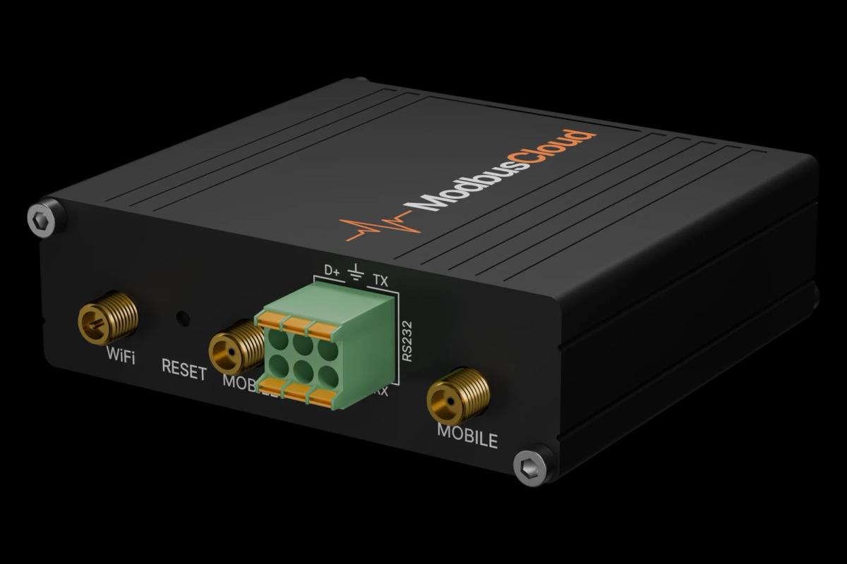
Wire the meter RS485 to RS485 A and B of the ModbusCloud Gateway with shielded twisted pair and terminate the bus.
Check address, baud rate and parity on the meter display; the default is address 1, 19200 baud, 8N1.
In ModbusCloud, add a second Modbus device with the same address and import this template.
Check that the aggregated values come in and match the readings on the meter display.
Things to watch for
Why do all aggregated values read zero?
The meter only fills the Class S values when Class S event detection is enabled and the model supports it. Check Class S PQ Event Enable and the meter model. Without voltage or current on the inputs the values also stay at zero.
The THD or unbalance values look 100 times too small or too large. What is wrong?
The template divides these values by 100. Compare one value with the meter display or its web page. If the display shows the value as it comes in, set the scale of those registers to 1 in your Modbus device in ModbusCloud.
Can I change the event thresholds from ModbusCloud?
Yes, the event settings are writable. Writing is off per gateway by default; request it on the Control tab of the gateway. Stay within the range in the register list, such as 10 to 90 percent for the sag threshold, and read the value back after writing.
Can I use this template together with the main Acuvim II template?
Yes. Add the meter twice on the same address, once with each template. They read different registers, so they do not conflict. Poll this template less often if the bus gets busy.


Want to see how it works?