








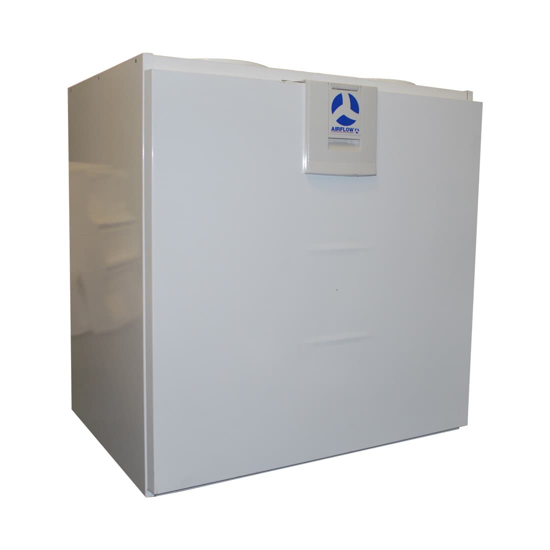
Airflow Adroit MVHR
Controls Airflow Adroit MVHR operating modes via Modbus RTU
Template for the Airflow Adroit MVHR ventilation unit over Modbus RTU. It reads temperatures, filter status, and operating state, and allows control of ventilation modes including boost, away, and at home.
- Protocol
- Modbus RTU
- Connection
- RS485, 19200 baud
- Registers
- 8, read and write
- Brand
- Airflow
- Key readings
- External Temperature · Limp Mode · Filter Change · MVHR State · MVHR Boost Timer
- Available commands
- MVHR State · MVHR Boost Timer · MVHR Fireplace Timer · Digital Input 1 Mode
- Compatible models
- Airflow Adroit MVHR
- Last updated
Registers (8)
5 read, 5 write
| Name | Unit | Access | Address (Hidden until you enter your email) | Function (hidden) | Type (hidden) |
|---|---|---|---|---|---|
| External Temperature | K | Read | |||
| Limp Mode | Read | ||||
| Filter Change | Read | ||||
| MVHR State | Read and write | ||||
| MVHR Boost Timer | Read and write | ||||
| MVHR Fireplace Timer | Write | ||||
| MVHR Extra Timer | Write | ||||
| Digital Input 1 Mode | Write |
Loading registers…
Send your device list
If a device is not in the library yet, we build the template for free as soon as we have the register data.
Use cases
- Monitor external temperature and MVHR operating state on a live cloud dashboard for each customer site.
- Create an alert when the filter change indicator activates so you can schedule maintenance proactively.
- Switch the Airflow Adroit between boost, away, and at home modes remotely without a site visit.
- Set the boost timer remotely when a customer reports condensation or poor air quality.
- Track limp mode events over time to identify recurring faults before they escalate.
- Activate the fireplace timer remotely to manage ventilation during wood burner use in winter.
Installation
Connect the Modbus RTU wiring (A, B, and GND) from the Airflow Adroit MVHR terminal block to the RS-485 port on your ModbusCloud Gateway.
Set the Modbus slave address on the Airflow Adroit unit using its onboard controls or configuration menu, and note the address for gateway setup.
Configure the serial port on the ModbusCloud gateway to 19200 baud, even parity (8E1), matching the Airflow Adroit default settings.
Import the Airflow Adroit MVHR template from the ModbusCloud template library into your gateway project.
Assign the correct Modbus slave address in the template to match the address configured on the physical unit.
Verify communication by checking live register values on the ModbusCloud dashboard, confirming that external temperature and MVHR state are reporting correctly.
Things to watch for
I am not getting any response from the Airflow Adroit on the Modbus bus. What should I check?
Verify that the baud rate is set to 19200 and parity is configured to even (8E1) on both the gateway and the MVHR unit. Also confirm that the A and B data lines are not swapped and that a 120 ohm termination resistor is placed at the end of the bus if the cable run is long.
Can I read and write the MVHR State register at the same time?
Yes. Registers 4609 (MVHR State) and 4612 (MVHR Boost Timer) are dual-purpose, meaning you read from and write to the same address. The template handles this automatically.
How do I know when the filter needs replacing?
The Filter Change register provides a status flag that indicates when the filter is due for replacement. You can configure a ModbusCloud alert on this register to receive a notification automatically.
Does the Airflow Adroit need a firmware update to support Modbus RTU?
Most Adroit units ship with Modbus RTU support enabled. If communication fails after verifying wiring and settings, consult the Airflow technical documentation or contact Airflow support to confirm your unit firmware version supports Modbus.






Want to see how it works?
