








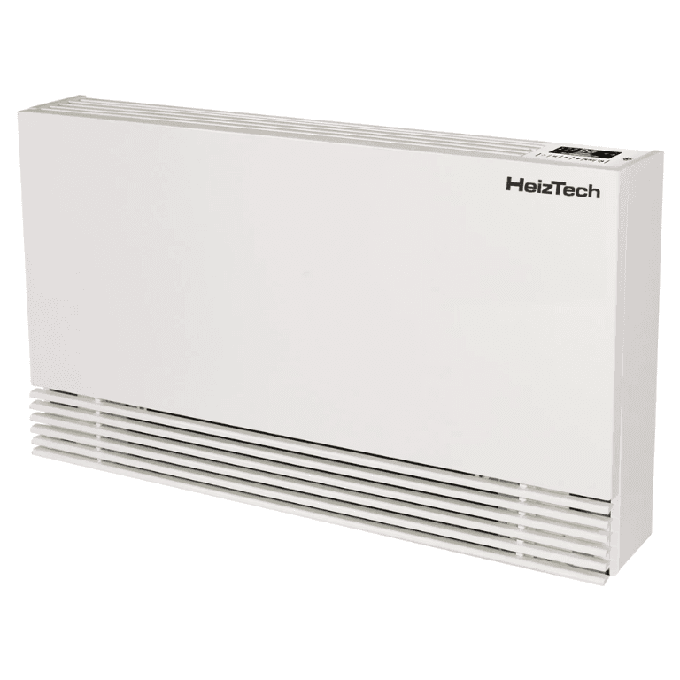
BM fan coil unit - C series
Controls HeizTech BM fan coil units via Modbus RTU for heating and cooling
This template integrates HeizTech BM C-series fan coil units via Modbus RTU. It reads air and water inlet temperatures, relay states, and fan speed, and allows control of set temperature, air volume, fan speed, and operating mode.
- Protocol
- Modbus RTU
- Connection
- RS485, 19200 baud
- Registers
- 15, read and write
- Brand
- HeizTech
- Key readings
- Air inlet temperature · Water inlet temperature · Relay 1 and 2 status · Fan speed · Setting mode · Working mode
- Available commands
- Set temperature · Set air volume · Setting mode · Fan speed
- Compatible models
- 70C BM200 · 70C BM400 · 70C BM600 · 70C BM800
- Last updated
Registers (15)
15 read, 13 write
| Name | Unit | Access | Address (Hidden until you enter your email) | Function (hidden) | Type (hidden) |
|---|---|---|---|---|---|
| Setting mode | Read and write | ||||
| Set temperature | °C | Read and write | |||
| Set air volume | Read and write | ||||
| Sleep function | Read and write | ||||
| Relay 1 | Read and write | ||||
| Relay 2 | Read and write | ||||
| Fan speed | rpm | Read and write | |||
| Air inlet temperature | °C | Read | |||
| Water inlet temperature | °C | Read | |||
| Working mode | Read and write | ||||
| Baud rate | Read and write | ||||
| Parity bit | Read and write | ||||
| Stop bit | Read and write | ||||
| Data bit | Read and write | ||||
| Modbus address | Read and write |
Loading registers…
Send your device list
If a device is not in the library yet, we build the template for free as soon as we have the register data.
Use cases
- Monitor air inlet and water inlet temperatures on a live dashboard for each fan coil zone.
- Set target temperature and air volume remotely to optimize comfort without on-site visits.
- Create an alert when a relay state changes unexpectedly or an E7 fault code appears.
- Aggregate heating and cooling runtime data across multiple fan coil units for energy reporting.
- Coordinate fan coil operation with heat pumps or boilers by reading working mode and fan speed.
Installation
Switch off power to the fan coil unit before accessing the PCB to eliminate the risk of electric shock.
Crimp a 4-pin male connector onto a twisted-pair cable and connect it to the 4-pin female connector on the fan coil PCB, crossing the A and B RS-485 lines because they are interchanged compared to standard wiring.
Connect the other end of the twisted pair to the RS-485 port on your ModbusCloud Gateway.
On the fan coil unit screen, set parameter 9 (485 communication) to off and assign a unique Modbus address in parameter 12 (range 1 to 16).
Configure the gateway serial port to 19200 bps baud rate, even parity, 1 stop bit, and 8 data bits to match the device defaults.
Import the HeizTech BM C-series template in the ModbusCloud platform and assign it to the correct gateway and Modbus address.
Things to watch for
The fan coil displays an E7 fault code after connecting Modbus. What is wrong?
Parameter 9 (485 communication) on the device must be turned off. Leaving it enabled causes the E7 fault and prevents Modbus communication. Disable it from the unit screen, then retry.
I cannot read any registers even though the wiring looks correct. What should I check?
The A and B RS-485 pins on the fan coil PCB are swapped compared to the standard convention. Cross the A and B lines at the fan coil connector. Also verify the baud rate is set to 19200 with even parity on your gateway.
Can I use this template with Energy Save or Amitime branded fan coils?
Yes. According to the manufacturer documentation, the BM fan coil hardware is identical across HeizTech, Energy Save, Amitime, and other brands. The same template and register map apply.
The documented register addresses do not match the readings I see. Why?
The HeizTech documentation uses 1-based register addresses. Subtract one to get the zero-based address used in standard Modbus communication. The template already accounts for this offset.






Want to see how it works?
