

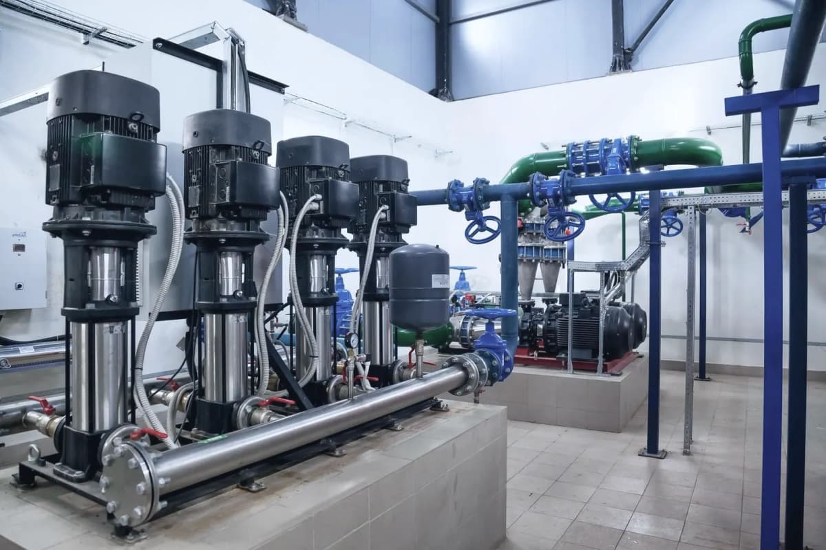
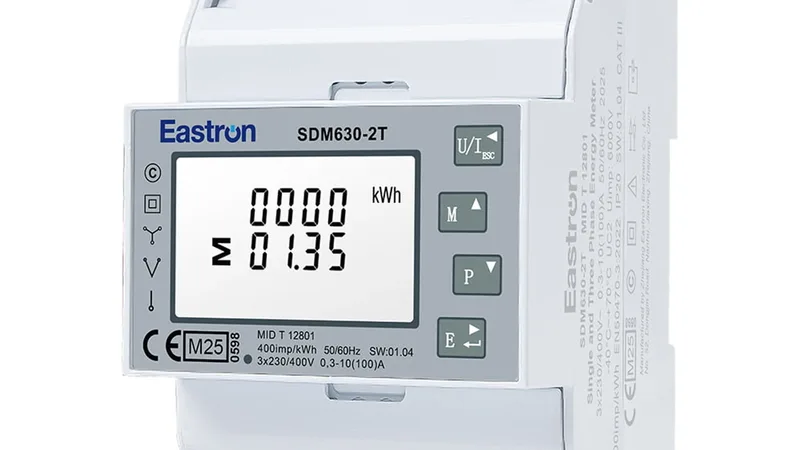

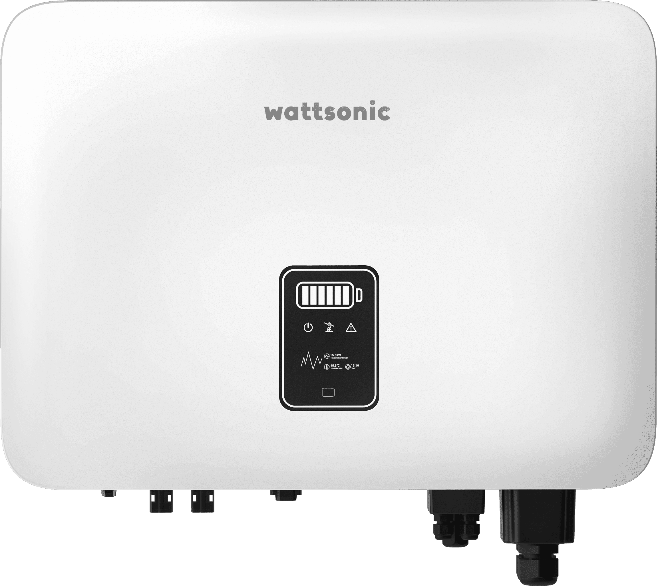
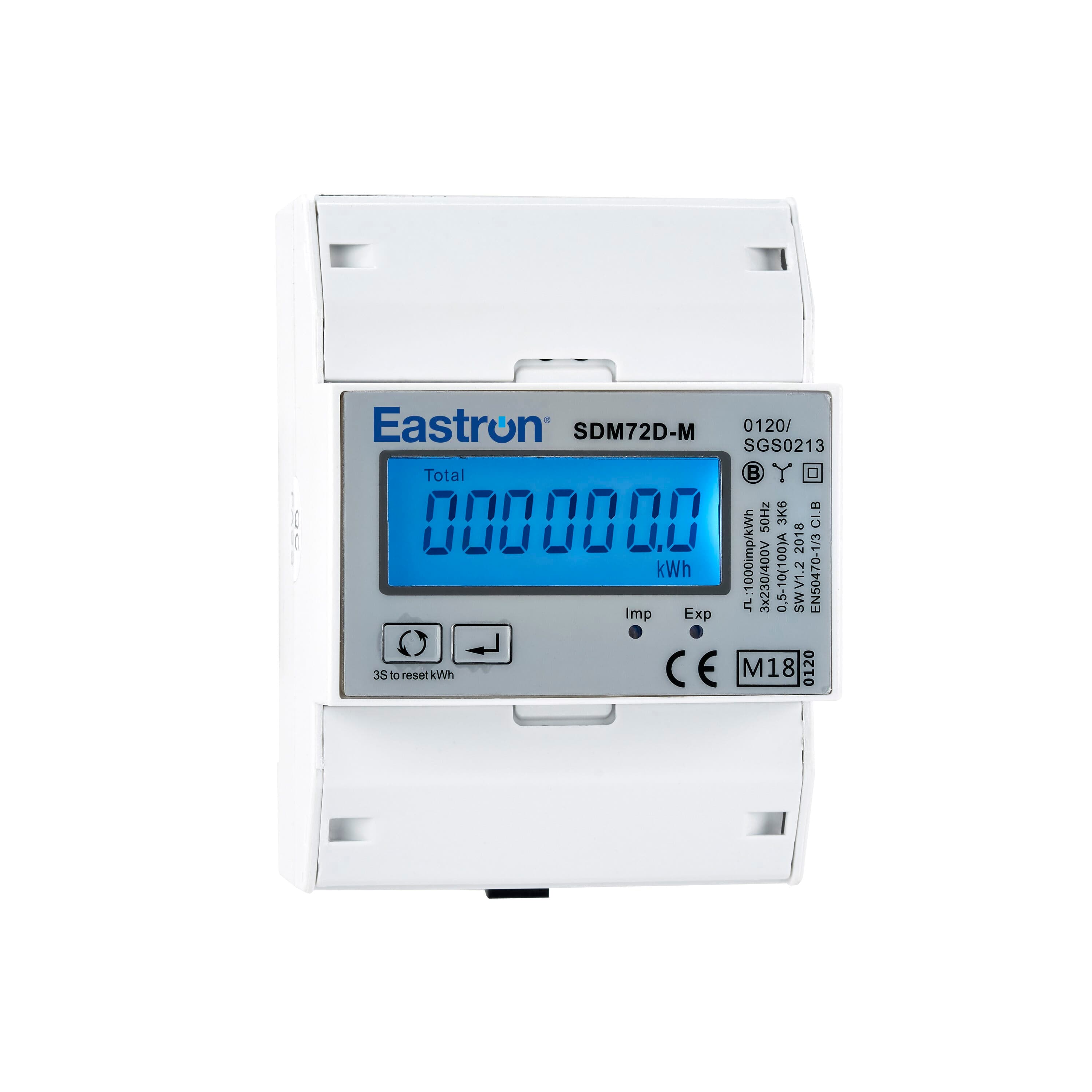
CPS SCA/SCH KTL-DO/US
Three-phase PV string inverters from 25 to 275 kW with AC, DC, energy, temperature and fault values over Modbus RTU.
The CPS SCA and SCH series from Chint Power Systems America are three-phase string inverters from 25 to 275 kW for commercial rooftops, carports and ground-mounted PV systems. This Modbus RTU template reads AC power, daily and total energy, grid values, DC voltage and current per MPPT, temperatures and fault codes, and lets you switch the inverter and limit its power from ModbusCloud.
- Protocol
- Modbus RTU
- Connection
- RS485, 9600 baud
- Registers
- 280, read and write
- Brand
- CPS
- Key readings
- AC active power · Daily and total energy · Grid voltage, current and frequency · DC voltage and current per MPPT · Power factor · Inverter temperatures · Operating mode · Fault and warning codes
- Available commands
- Remote on and off · Active power limit · Power factor setpoint · Reactive power setpoint · Inverter clock
- Compatible models
- SCA25KTL-DO/US-208 · SCA25KTL-DO-R/US-480 · SCA36KTL-DO/US-480 · SCA50KTL-DO/US-480 · SCA60KTL-DO/US-480 · SCH100KTL-DO/US-480 · SCH100KTL-DO/US-600 · SCH125KTL-DO/US-600 · SCH275KTL-DO/US-800
- Last updated
Registers (280)
280 read, 35 write
| Name | Unit | Access | Address (Hidden until you enter your email) | Function (hidden) | Type (hidden) |
|---|---|---|---|---|---|
| AC Active Power | kW | Read | |||
| Total Energy | kWh | Read | |||
| Daily Energy | kWh | Read | |||
| AC Apparent Power | kVA | Read | |||
| AC Reactive Power | kvar | Read | |||
| Power Factor | Read | ||||
| Grid Voltage AB | V | Read | |||
| Grid Voltage BC | V | Read | |||
| Grid Voltage CA | V | Read | |||
| Grid Current Phase A | A | Read | |||
| Grid Current Phase B | A | Read | |||
| Grid Current Phase C | A | Read | |||
| Grid Frequency | Hz | Read | |||
| PV Input Power | kW | Read | |||
| MPPT1 Voltage | V | Read | |||
| MPPT1 Current | A | Read | |||
| MPPT2 Voltage | V | Read | |||
| MPPT2 Current | A | Read | |||
| MPPT3 Voltage | V | Read | |||
| MPPT3 Current | A | Read | |||
| MPPT4 Voltage | V | Read | |||
| MPPT4 Current | A | Read | |||
| MPPT5 Voltage | V | Read | |||
| MPPT5 Current | A | Read | |||
| MPPT6 Voltage | V | Read | |||
| MPPT6 Current | A | Read | |||
| MPPT7 Voltage | V | Read | |||
| MPPT7 Current | A | Read | |||
| MPPT8 Voltage | V | Read | |||
| MPPT8 Current | A | Read | |||
| MPPT9 Voltage | V | Read | |||
| MPPT9 Current | A | Read | |||
| MPPT10 Voltage | V | Read | |||
| MPPT10 Current | A | Read | |||
| MPPT11 Voltage | V | Read | |||
| MPPT11 Current | A | Read | |||
| MPPT12 Voltage | V | Read | |||
| MPPT12 Current | A | Read | |||
| Heatsink Temperature | °C | Read | |||
| Ambient Temperature | °C | Read | |||
| Transformer Temperature | °C | Read | |||
| Daily Peak Active Power | kW | Read | |||
| Daily Operating Time | min | Read | |||
| Efficiency | % | Read | |||
| Operating Mode | Read | ||||
| Permanent Fault Word | Read | ||||
| Warning Word | Read | ||||
| Fault Word 0 | Read | ||||
| Fault Word 1 | Read | ||||
| Fault Word 2 | Read | ||||
| Fault Word 3 | Read | ||||
| Fault Word 4 | Read | ||||
| Fault Word 5 | Read | ||||
| Fault Word 6 | Read | ||||
| Warning Word 1 | Read | ||||
| Fault Timestamp Year | Read | ||||
| Fault Timestamp Month Day | Read | ||||
| Fault Timestamp Hour Minute | Read | ||||
| Fault Timestamp Second | Read | ||||
| Maximum Active Power | kW | Read | |||
| Maximum Apparent Power | kVA | Read | |||
| Bus Capacitance | Read | ||||
| AC Capacitance | Read | ||||
| PID Box Enable | Read | ||||
| PID Box Voltage | V | Read | |||
| PID Box Current | mA | Read | |||
| PV Detection | Read | ||||
| Inverter State 1 | Read | ||||
| Inverter State Info 1 | Read | ||||
| Power Factor Setting Readback | Read | ||||
| Remote Active Power Command Readback | % | Read | |||
| Remote Reactive Power Command Readback | % | Read | |||
| Device Type Code | Read | ||||
| Model Name | Read | ||||
| Serial Number Word 1 | Read | ||||
| Serial Number Word 2 | Read | ||||
| Serial Number Word 3 | Read | ||||
| Serial Number Word 4 | Read | ||||
| Protocol Version | Read | ||||
| Major Version | Read | ||||
| Minor Version | Read | ||||
| DSP Safety Version | Read | ||||
| Input Register Count | Read | ||||
| Holding Register Count | Read | ||||
| Holding Register Start Address | Read | ||||
| Remote On Off | Read and write | ||||
| Active Power Limit | % | Read and write | |||
| Power Factor Setpoint | Read and write | ||||
| Reactive Power Setpoint | % | Read and write | |||
| Clock Set Year | Read and write | ||||
| Clock Set Month Day | Read and write | ||||
| Clock Set Hour Minute | Read and write | ||||
| Clock Set Second | Read and write | ||||
| Reactive Power Mode Select | Read and write | ||||
| Clear Arc Fault | Read and write | ||||
| Anti Reflux Delay | s | Read and write | |||
| Ethernet Card Serial Word 1 | Read and write | ||||
| Ethernet Card Serial Word 2 | Read and write | ||||
| Ethernet Card Serial Word 3 | Read and write | ||||
| Ethernet Card Serial Word 4 | Read and write | ||||
| Ethernet Card IP Address | Read and write | ||||
| Ethernet Card Subnet Mask | Read and write | ||||
| Ethernet Card Default Gateway | Read and write | ||||
| Ethernet Card DNS Server | Read and write | ||||
| Ethernet Card Address Range | Read and write | ||||
| Power On Off Command | Read and write | ||||
| Force Restart | Read and write | ||||
| Factory Reset | Read and write | ||||
| Auto Test | Read and write | ||||
| MPPT Scan | Read and write | ||||
| Arc Detection Test | Read and write | ||||
| Arc Alarm Clear | Read and write | ||||
| Remote Power Factor Setpoint | Read and write | ||||
| Remote Active Power Setpoint | % | Read and write | |||
| Remote Reactive Power Setpoint | % | Read and write | |||
| Second Frequency Protection Enable | Read and write | ||||
| PID SVG Enable | Read and write | ||||
| SVG Work Mode Enable | Read and write | ||||
| SVG Reactive Setpoint | % | Read and write | |||
| PID System Type | Read and write | ||||
| Line Voltage AB | V | Read | |||
| Line Voltage BC | V | Read | |||
| Line Voltage CA | V | Read | |||
| Phase Voltage A | V | Read | |||
| Phase Voltage B | V | Read | |||
| Phase Voltage C | V | Read | |||
| Grid Frequency Phase A | Hz | Read | |||
| Grid Frequency Phase B | Hz | Read | |||
| Grid Frequency Phase C | Hz | Read | |||
| Grid Phase Sequence | Read | ||||
| Grid Voltage Unbalance | % | Read | |||
| Grid System Frequency | Hz | Read | |||
| Neutral To Earth Voltage | V | Read | |||
| MCU Grid Current A | A | Read | |||
| MCU Grid Current B | A | Read | |||
| MCU Grid Current C | A | Read | |||
| MCU Grid Voltage A | V | Read | |||
| MCU Grid Voltage B | V | Read | |||
| MCU Grid Voltage C | V | Read | |||
| Voltage Harmonics L1 | % | Read | |||
| Voltage Harmonics L2 | % | Read | |||
| Voltage Harmonics L3 | % | Read | |||
| Current Harmonics L1 | % | Read | |||
| Current Harmonics L2 | % | Read | |||
| Current Harmonics L3 | % | Read | |||
| Neutral Grounded Status | Read | ||||
| Current TRD L1 | % | Read | |||
| Current TRD L2 | % | Read | |||
| Current TRD L3 | % | Read | |||
| Output Current Phase A | A | Read | |||
| Output Current Phase B | A | Read | |||
| Output Current Phase C | A | Read | |||
| Active Power Phase A | kW | Read | |||
| Active Power Phase B | kW | Read | |||
| Active Power Phase C | kW | Read | |||
| Active Power Total | kW | Read | |||
| Reactive Power Phase A | kvar | Read | |||
| Reactive Power Phase B | kvar | Read | |||
| Reactive Power Phase C | kvar | Read | |||
| Reactive Power Total | kvar | Read | |||
| Power Factor Phase A | Read | ||||
| Power Factor Phase B | Read | ||||
| Power Factor Phase C | Read | ||||
| Power Factor Total | Read | ||||
| Inverter Voltage Phase A | V | Read | |||
| Inverter Voltage Phase B | V | Read | |||
| Inverter Voltage Phase C | V | Read | |||
| Active Power Reference | % | Read | |||
| Reactive Power Reference | % | Read | |||
| Power Factor Reference | Read | ||||
| Apparent Power Phase A | kVA | Read | |||
| Apparent Power Phase B | kVA | Read | |||
| Apparent Power Phase C | kVA | Read | |||
| Apparent Power Total | kVA | Read | |||
| PV Input Mode | Read | ||||
| DC Input Power | kW | Read | |||
| DC Input 1 Voltage | V | Read | |||
| DC Input 1 Current | A | Read | |||
| DC Input 2 Voltage | V | Read | |||
| DC Input 2 Current | A | Read | |||
| DC Input 3 Voltage | V | Read | |||
| DC Input 3 Current | A | Read | |||
| Boost 1 Current | A | Read | |||
| Boost 2 Current | A | Read | |||
| Boost 3 Current | A | Read | |||
| Boost 4 Current | A | Read | |||
| Boost 5 Current | A | Read | |||
| Boost 6 Current | A | Read | |||
| MPPT 1 Current Detail | A | Read | |||
| MPPT 2 Current Detail | A | Read | |||
| MPPT 3 Current Detail | A | Read | |||
| IV Curve 1 Read Status | Read | ||||
| IV Curve 2 Read Status | Read | ||||
| IV Curve 3 Read Status | Read | ||||
| MPPT 1 Scan Peak Power | kW | Read | |||
| MPPT 1 Scan Peak Voltage | V | Read | |||
| MPPT 2 Scan Peak Power | kW | Read | |||
| MPPT 2 Scan Peak Voltage | V | Read | |||
| MPPT 3 Scan Peak Power | kW | Read | |||
| MPPT 3 Scan Peak Voltage | V | Read | |||
| DC Input 4 Voltage | V | Read | |||
| DC Input 4 Current | A | Read | |||
| DC Input 5 Voltage | V | Read | |||
| DC Input 5 Current | A | Read | |||
| DC Input 6 Voltage | V | Read | |||
| DC Input 6 Current | A | Read | |||
| DC Input 7 Voltage | V | Read | |||
| DC Input 7 Current | A | Read | |||
| DC Input 8 Voltage | V | Read | |||
| DC Input 8 Current | A | Read | |||
| DC Input 9 Voltage | V | Read | |||
| DC Input 9 Current | A | Read | |||
| DC Input 10 Voltage | V | Read | |||
| DC Input 10 Current | A | Read | |||
| DC Input 11 Voltage | V | Read | |||
| DC Input 11 Current | A | Read | |||
| DC Input 12 Voltage | V | Read | |||
| DC Input 12 Current | A | Read | |||
| String 1 Current | A | Read | |||
| String 2 Current | A | Read | |||
| String 3 Current | A | Read | |||
| String 4 Current | A | Read | |||
| String 5 Current | A | Read | |||
| String 6 Current | A | Read | |||
| String 7 Current | A | Read | |||
| String 8 Current | A | Read | |||
| String 9 Current | A | Read | |||
| String 10 Current | A | Read | |||
| String 11 Current | A | Read | |||
| String 12 Current | A | Read | |||
| String 13 Current | A | Read | |||
| String 14 Current | A | Read | |||
| String 15 Current | A | Read | |||
| String 16 Current | A | Read | |||
| String 17 Current | A | Read | |||
| String 18 Current | A | Read | |||
| String 19 Current | A | Read | |||
| String 20 Current | A | Read | |||
| String 21 Current | A | Read | |||
| String 22 Current | A | Read | |||
| String 23 Current | A | Read | |||
| String 24 Current | A | Read | |||
| Operating Mode Bits | Read | ||||
| Power On Off Feedback | Read | ||||
| Module Temperature | °C | Read | |||
| Internal Temperature | °C | Read | |||
| Insulation Resistance | kΩ | Read | |||
| Leakage Current | mA | Read | |||
| DC Injection Phase A | mA | Read | |||
| DC Injection Phase B | mA | Read | |||
| DC Injection Phase C | mA | Read | |||
| Positive Bus Voltage | V | Read | |||
| Negative Bus Voltage | V | Read | |||
| Bus Voltage Total | V | Read | |||
| Start Countdown | s | Read | |||
| ISO Sampling Voltage | V | Read | |||
| Bus Capacitance Status | Read | ||||
| AC Capacitance Status | Read | ||||
| Environment Temperature 2 | °C | Read | |||
| Relay Board Temperature | °C | Read | |||
| Power Board Temperature | °C | Read | |||
| Boost Temperature | °C | Read | |||
| Derating State | Read | ||||
| Environment Temperature 2b | °C | Read | |||
| External Environment Temperature | °C | Read | |||
| MCU Environment Temperature | °C | Read | |||
| MCU Relay Temperature | °C | Read | |||
| Power State | Read | ||||
| NPE Voltage | V | Read | |||
| AC Voltage Rating | V | Read | |||
| Internal Warning Word | Read | ||||
| Internal Fault Word 0 | Read | ||||
| Internal Fault Word 1 | Read | ||||
| Internal Fault Word 2 | Read | ||||
| Internal Fault Word 3 | Read | ||||
| Internal Fault Word 4 | Read | ||||
| Internal Permanent Fault Word | Read | ||||
| Internal Fault Word 5 | Read | ||||
| Internal Fault Word 6 | Read | ||||
| Internal Warning Word 1 | Read |
Loading registers…
Send your device list
If a device is not in the library yet, we build the template for free as soon as we have the register data.
Use cases
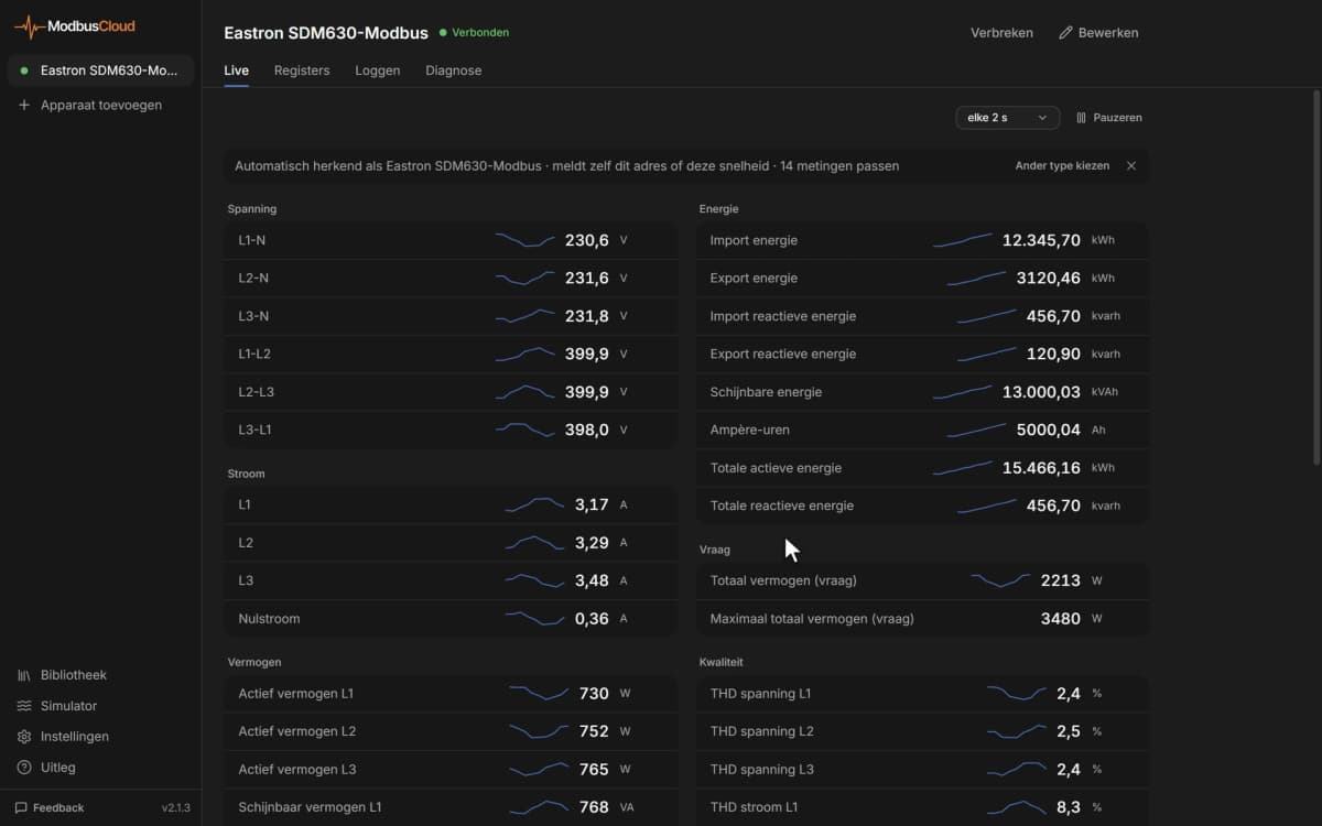
- Show AC power and daily energy of every inverter on one ModbusCloud dashboard next to the energy meter of the site.
- Get an email alert when a fault word is not zero or the operating mode changes to fault.
- Compare DC current per MPPT input in the history to find a string that underperforms or is disconnected.
- Track heatsink and ambient temperature through the hot season to see when the inverter derates.
- Lower the active power limit from ModbusCloud by hand or with an automation on a schedule or energy price.
Installation
Open the wire box and connect RS485 A and B to the communication board: on SCA models pins 3 (A+) and 4 (B-) of the 5-pin connector, on SCH models the A and B pins of the 6-pin connector.
Daisy-chain several inverters with shielded twisted pair, ground the shield at one end, and turn on the termination switch only on the last inverter of the bus.
Give each inverter a unique Modbus address and the same baud rate, default 9600, on the LCD of SCA models or in the CPS Connect Pro app of SCH models.
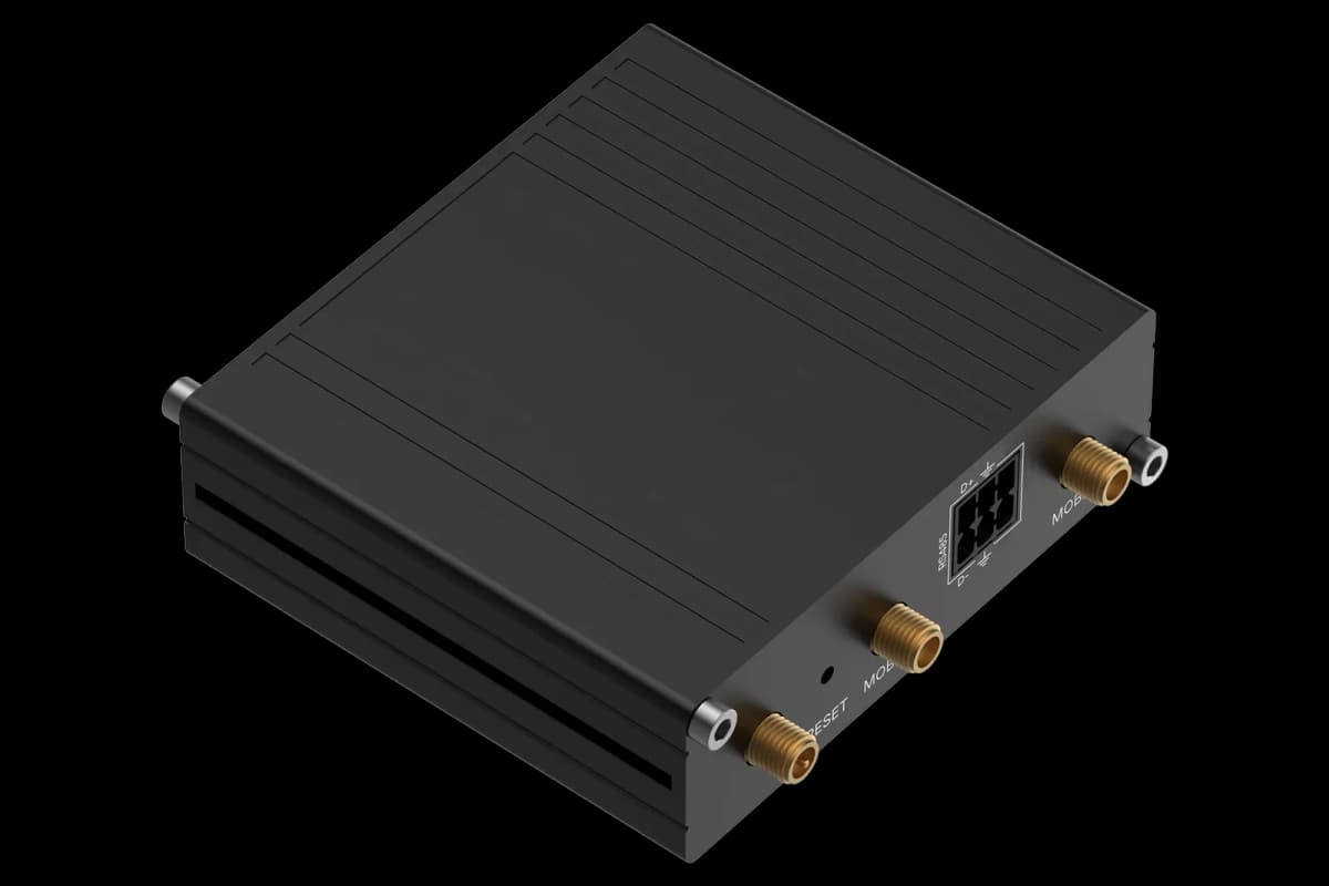
In ModbusCloud, add a Modbus device on the RS485 port of the ModbusCloud Gateway with that address, 9600 baud, 8 data bits, no parity and 1 stop bit, and import this template.
Check that Model Name and AC Active Power show plausible values, then remove the registers your model does not have.
Things to watch for
The Gateway gets no answer from the inverter. What should I check?
Check that address and baud rate in ModbusCloud match the inverter, default 9600 baud with 8 data bits, no parity and 1 stop bit, and that no two inverters share an address. Swap A and B if nothing answers. Use the network terminals on the communication board, not the debug port, and turn on the termination switch only at the end of the bus.
Why do some registers read 65535, -32768 or nothing at all?
Not every model has every value. The SCH100KTL and SCH125KTL have one MPPT input, so inputs 2 and 3 stay empty, and MPPT inputs 4 to 12 and the string currents exist only on the SCH275KTL. The inverter marks a value it does not provide with 65535 or -32768. Remove those registers from the device.
How do I set an alarm on inverter faults?
Each warning and fault register is a set of bits, and 0 means nothing is active. Create an alarm rule with not equal to 0 on Permanent Fault Word, Warning Word and Fault Word 0 to 4. Which bit means what differs per model, so look up the bit in the event table of your inverter.
How do I limit power or switch the inverter off from ModbusCloud?
Writing registers is off per gateway by default; request it for the gateway in the portal first. Active Power Limit takes 0 to 100 percent of rated power, Remote On Off takes 43690 to start and 21845 to stop. On the SCH275KTL use Remote Active Power Setpoint and Power On Off Command. Check the result in Operating Mode and AC Active Power.
Can I connect several CPS inverters to one Gateway?
Yes. Daisy-chain up to 32 inverters on one RS485 bus, give each a unique address and the same baud rate, and add each inverter in ModbusCloud as its own Modbus device with this template.




Want to see how it works?