

Delta VFD-E
Compact AC motor drive with run control, speed setpoint and full parameter access.
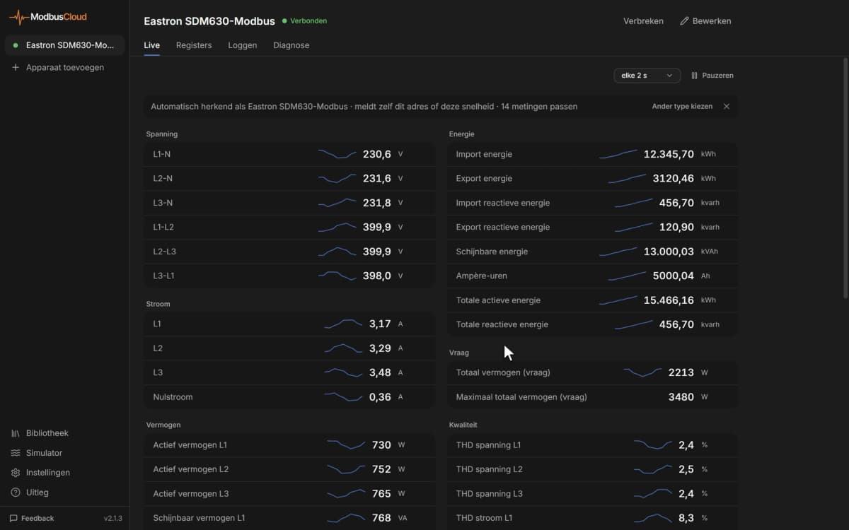
The Delta VFD-E is a compact AC motor drive that controls the speed of three-phase motors in pumps, fans, conveyors and small machines. This Modbus RTU template reads frequency, current, voltage, temperature, status and error codes, and lets you start, stop and set the speed and all drive parameters from ModbusCloud.
- Protocol
- Modbus RTU
- Connection
- RS485, 9600 baud
- Registers
- 311, read and write
- Brand
- Delta
- Key readings
- Output frequency · Output current · Output voltage · DC bus voltage · IGBT temperature · Error code · Drive status
- Available commands
- Run and stop · Direction · Frequency setpoint · Fault reset · Acceleration time · Deceleration time
- Compatible models
- VFD-E (VFD002E to VFD220E, 115 V, 230 V and 460 V)
- Last updated
Registers (311)
308 read, 282 write
| Name | Unit | Access | Address (Hidden until you enter your email) | Function (hidden) | Type (hidden) |
|---|---|---|---|---|---|
| Output Frequency | Hz | Read | 8451 | FC03 | uint16 |
| Output Current | A | Read | 8452 | FC03 | uint16 |
| Output Voltage | V | Read | 8457 | FC03 | uint16 |
| DC Bus Voltage | V | Read | 8456 | FC03 | uint16 |
| IGBT Temperature | °C | Read | 8458 | FC03 | uint16 |
| Frequency Command | Hz | Read | |||
| Error Code | Read | ||||
| Drive Status | Read | ||||
| User Defined Value Low Word | Read | ||||
| User Defined Value High Word | Read | ||||
| Run Command Word | Write | ||||
| Frequency Setpoint | Hz | Write | |||
| External Fault and Reset Command | Write | ||||
| Drive Identity Code | Read | ||||
| Drive Rated Current | A | Read | |||
| Parameter Reset | Read and write | ||||
| Start-up Display Selection | Read and write | ||||
| Multi-function Display Content | Read and write | ||||
| User Defined Coefficient K | Read and write | ||||
| Power Board Software Version | Read | ||||
| Control Board Software Version | Read | ||||
| Password Input | Read and write | ||||
| Password Set | Read and write | ||||
| Control Method | Read and write | ||||
| 50 Hz Base Voltage Selection | Read and write | ||||
| Maximum Output Frequency | Hz | Read and write | |||
| Maximum Voltage Frequency Motor 0 | Hz | Read and write | |||
| Maximum Output Voltage Motor 0 | V | Read and write | |||
| Mid-Point Frequency Motor 0 | Hz | Read and write | |||
| Mid-Point Voltage Motor 0 | V | Read and write | |||
| Minimum Output Frequency Motor 0 | Hz | Read and write | |||
| Minimum Output Voltage Motor 0 | V | Read and write | |||
| Maximum Voltage Frequency Motor 1 | Hz | Read and write | |||
| Maximum Output Voltage Motor 1 | V | Read and write | |||
| Mid-Point Frequency Motor 1 | Hz | Read and write | |||
| Mid-Point Voltage Motor 1 | V | Read and write | |||
| Minimum Output Frequency Motor 1 | Hz | Read and write | |||
| Minimum Output Voltage Motor 1 | V | Read and write | |||
| Maximum Voltage Frequency Motor 2 | Hz | Read and write | |||
| Maximum Output Voltage Motor 2 | V | Read and write | |||
| Mid-Point Frequency Motor 2 | Hz | Read and write | |||
| Mid-Point Voltage Motor 2 | V | Read and write | |||
| Minimum Output Frequency Motor 2 | Hz | Read and write | |||
| Minimum Output Voltage Motor 2 | V | Read and write | |||
| Maximum Voltage Frequency Motor 3 | Hz | Read and write | |||
| Maximum Output Voltage Motor 3 | V | Read and write | |||
| Mid-Point Frequency Motor 3 | Hz | Read and write | |||
| Mid-Point Voltage Motor 3 | V | Read and write | |||
| Minimum Output Frequency Motor 3 | Hz | Read and write | |||
| Minimum Output Voltage Motor 3 | V | Read and write | |||
| Output Frequency Upper Limit | % | Read and write | |||
| Output Frequency Lower Limit | % | Read and write | |||
| Acceleration Time 1 | s | Read and write | |||
| Deceleration Time 1 | s | Read and write | |||
| Acceleration Time 2 | s | Read and write | |||
| Deceleration Time 2 | s | Read and write | |||
| Jog Acceleration Time | s | Read and write | |||
| Jog Deceleration Time | s | Read and write | |||
| Jog Frequency | Hz | Read and write | |||
| Auto Acceleration Deceleration Mode | Read and write | ||||
| Acceleration S-Curve | s | Read and write | |||
| Deceleration S-Curve | s | Read and write | |||
| Accel Decel Time Unit | Read and write | ||||
| Simple Position Delay at 0 Hz | s | Read and write | |||
| Simple Position Delay at 10 Hz | s | Read and write | |||
| Simple Position Delay at 20 Hz | s | Read and write | |||
| Simple Position Delay at 30 Hz | s | Read and write | |||
| Simple Position Delay at 40 Hz | s | Read and write | |||
| Simple Position Delay at 50 Hz | s | Read and write | |||
| First Frequency Command Source | Read and write | ||||
| First Operation Command Source | Read and write | ||||
| Stop Method | Read and write | ||||
| PWM Carrier Frequency | Read and write | ||||
| Motor Direction Control | Read and write | ||||
| Power-On and Command Source Change Behaviour | Read and write | ||||
| Loss of ACI Signal Treatment | Read and write | ||||
| Up Down Mode | Read and write | ||||
| Up Down Constant Speed Rate | Read and write | ||||
| Second Frequency Command Source | Read and write | ||||
| First and Second Frequency Combination | Read and write | ||||
| Keypad Frequency Command | Hz | Read and write | |||
| Communication Frequency Command | Hz | Read and write | |||
| Saved Frequency Command Selection | Read and write | ||||
| Initial Frequency Selection | Read and write | ||||
| Initial Frequency Setpoint | Hz | Read and write | |||
| Frequency Command Source Display | Read | ||||
| Operation Command Source Display | Read | ||||
| Carrier Modulation Selection | Read and write | ||||
| Relay Output RA1 Function | Read and write | ||||
| MO1 Output Function | Read and write | ||||
| Desired Frequency 1 | Hz | Read and write | |||
| Analog Output Signal Selection | Read and write | ||||
| Analog Output Gain | % | Read and write | |||
| Terminal Count Value | Read and write | ||||
| Preliminary Count Value | Read and write | ||||
| EF on Terminal Count Attained | Read and write | ||||
| Fan Control | Read and write | ||||
| Digital Outputs Used by PLC | Read | ||||
| Analog Outputs Used by PLC | Read | ||||
| Brake Release Frequency | Hz | Read and write | |||
| Brake Engage Frequency | Hz | Read and write | |||
| Multi-function Output Status | Read | ||||
| Desired Frequency 2 | Hz | Read and write | |||
| Keypad Potentiometer Bias | % | Read and write | |||
| Keypad Potentiometer Bias Polarity | Read and write | ||||
| Keypad Potentiometer Gain | % | Read and write | |||
| Keypad Potentiometer Negative Bias Reverse | Read and write | ||||
| Two or Three Wire Control Mode | Read and write | ||||
| MI3 Input Function | Read and write | ||||
| MI4 Input Function | Read and write | ||||
| MI5 Input Function | Read and write | ||||
| MI6 Input Function | Read and write | ||||
| Input Contact Type Selection | Read and write | ||||
| Digital Input Debounce Time | Read and write | ||||
| Minimum AVI Voltage | V | Read and write | |||
| Minimum AVI Frequency | % | Read and write | |||
| Maximum AVI Voltage | V | Read and write | |||
| Maximum AVI Frequency | % | Read and write | |||
| Minimum ACI Current | mA | Read and write | |||
| Minimum ACI Frequency | % | Read and write | |||
| Maximum ACI Current | mA | Read and write | |||
| Maximum ACI Frequency | % | Read and write | |||
| ACI or AVI2 Selection | Read and write | ||||
| Minimum AVI2 Voltage | V | Read and write | |||
| Minimum AVI2 Frequency | % | Read and write | |||
| Maximum AVI2 Voltage | V | Read and write | |||
| Maximum AVI2 Frequency | % | Read and write | |||
| Digital Inputs Used by PLC | Read | ||||
| Analog Inputs Used by PLC | Read | ||||
| Multi-function Input Status | Read | ||||
| Internal or External Input Selection | Read and write | ||||
| Internal Input Terminal Status | Read and write | ||||
| 1st Step Speed Frequency | Hz | Read and write | |||
| 2nd Step Speed Frequency | Hz | Read and write | |||
| 3rd Step Speed Frequency | Hz | Read and write | |||
| 4th Step Speed Frequency | Hz | Read and write | |||
| 5th Step Speed Frequency | Hz | Read and write | |||
| 6th Step Speed Frequency | Hz | Read and write | |||
| 7th Step Speed Frequency | Hz | Read and write | |||
| 8th Step Speed Frequency | Hz | Read and write | |||
| 9th Step Speed Frequency | Hz | Read and write | |||
| 10th Step Speed Frequency | Hz | Read and write | |||
| 11th Step Speed Frequency | Hz | Read and write | |||
| 12th Step Speed Frequency | Hz | Read and write | |||
| 13th Step Speed Frequency | Hz | Read and write | |||
| 14th Step Speed Frequency | Hz | Read and write | |||
| 15th Step Speed Frequency | Hz | Read and write | |||
| Over-Voltage Stall Prevention Level | V | Read and write | |||
| Over-Current Stall Level During Accel | % | Read and write | |||
| Over-Current Stall Level During Operation | % | Read and write | |||
| Over-Torque Detection Mode | Read and write | ||||
| Over-Torque Detection Level | % | Read and write | |||
| Over-Torque Detection Time | s | Read and write | |||
| Electronic Thermal Overload Selection | Read and write | ||||
| Electronic Thermal Characteristic | s | Read and write | |||
| Present Fault Record | Read | ||||
| Second Most Recent Fault | Read | ||||
| Third Most Recent Fault | Read | ||||
| Fourth Most Recent Fault | Read | ||||
| Fifth Most Recent Fault | Read | ||||
| Motor Rated Current Motor 0 | A | Read and write | |||
| Motor No-Load Current Motor 0 | A | Read and write | |||
| Torque Compensation Motor 0 | Read and write | ||||
| Slip Compensation Motor 0 | Read and write | ||||
| Line-to-Line Resistance Motor 0 | Read and write | ||||
| Motor Rated Slip Motor 0 | Hz | Read and write | |||
| Motor Auto Tuning | Read and write | ||||
| Slip Compensation Limit | % | Read and write | |||
| Torque Compensation Time Constant | s | Read and write | |||
| Slip Compensation Time Constant | s | Read and write | |||
| Motor Operation Time Minutes | min | Read and write | |||
| Motor Operation Time Days | d | Read and write | |||
| Motor PTC Protection | Read and write | ||||
| PTC Input Debounce Time | Read and write | ||||
| PTC Overheat Protection Level | V | Read and write | |||
| PTC Overheat Warning Level | V | Read and write | |||
| PTC Overheat Reset Delta Level | V | Read and write | |||
| PTC Overheat Treatment | Read and write | ||||
| Motor Rated Current Motor 1 | A | Read and write | |||
| Motor No-Load Current Motor 1 | A | Read and write | |||
| Torque Compensation Motor 1 | Read and write | ||||
| Slip Compensation Motor 1 | Read and write | ||||
| Line-to-Line Resistance Motor 1 | Read and write | ||||
| Motor Rated Slip Motor 1 | Hz | Read and write | |||
| Motor Pole Number Motor 1 | Read and write | ||||
| Motor Rated Current Motor 2 | A | Read and write | |||
| Motor No-Load Current Motor 2 | A | Read and write | |||
| Torque Compensation Motor 2 | Read and write | ||||
| Slip Compensation Motor 2 | Read and write | ||||
| Line-to-Line Resistance Motor 2 | Read and write | ||||
| Motor Rated Slip Motor 2 | Hz | Read and write | |||
| Motor Pole Number Motor 2 | Read and write | ||||
| Motor Rated Current Motor 3 | A | Read and write | |||
| Motor No-Load Current Motor 3 | A | Read and write | |||
| Torque Compensation Motor 3 | Read and write | ||||
| Slip Compensation Motor 3 | Read and write | ||||
| Line-to-Line Resistance Motor 3 | Read and write | ||||
| Motor Rated Slip Motor 3 | Hz | Read and write | |||
| Motor Pole Number Motor 3 | Read and write | ||||
| DC Brake Current Level | % | Read and write | |||
| DC Brake Time at Start | s | Read and write | |||
| DC Brake Time at Stop | s | Read and write | |||
| DC Brake Start Frequency | Hz | Read and write | |||
| Momentary Power Loss Operation | Read and write | ||||
| Maximum Power Loss Time | s | Read and write | |||
| Base Block Speed Search | Read and write | ||||
| Base Block Time for Speed Search | s | Read and write | |||
| Speed Search Current Limit | % | Read and write | |||
| Skip Frequency 1 Upper Limit | Hz | Read and write | |||
| Skip Frequency 1 Lower Limit | Hz | Read and write | |||
| Skip Frequency 2 Upper Limit | Hz | Read and write | |||
| Skip Frequency 2 Lower Limit | Hz | Read and write | |||
| Skip Frequency 3 Upper Limit | Hz | Read and write | |||
| Skip Frequency 3 Lower Limit | Hz | Read and write | |||
| Auto Restart After Fault Count | Read and write | ||||
| Auto Reset Time After Fault | s | Read and write | |||
| Auto Energy Saving | Read and write | ||||
| AVR Function | Read and write | ||||
| Software Brake Level | V | Read and write | |||
| Motor Instability Compensation | Read and write | ||||
| OOB Sampling Time | s | Read and write | |||
| Number of OOB Sampling Times | Read and write | ||||
| OOB Average Sampling Angle | Read | ||||
| DEB Function | Read and write | ||||
| DEB Return Time | s | Read and write | |||
| Speed Search at Start-up | Read and write | ||||
| Speed Search Frequency at Start-up | Read and write | ||||
| Communication Address | Read and write | ||||
| Transmission Speed | Read and write | ||||
| Transmission Fault Treatment | Read and write | ||||
| Communication Time-out | s | Read and write | |||
| Communication Protocol | Read and write | ||||
| Response Delay Time | Read and write | ||||
| USB Card Transmission Speed | Read and write | ||||
| USB Card Communication Protocol | Read and write | ||||
| USB Card Transmission Fault Treatment | Read and write | ||||
| USB Card Communication Time-out | s | Read and write | |||
| PLC Communication Port | Read and write | ||||
| PID Setpoint Source | Read and write | ||||
| PID Feedback Input | Read and write | ||||
| PID Proportional Gain | Read and write | ||||
| PID Integral Time | s | Read and write | |||
| PID Derivative Time | s | Read and write | |||
| PID Integral Upper Bound | % | Read and write | |||
| PID Primary Delay Filter Time | s | Read and write | |||
| PID Output Frequency Limit | % | Read and write | |||
| PID Feedback Loss Detection Time | s | Read and write | |||
| PID Feedback Error Treatment | Read and write | ||||
| PID Detection Gain | Read and write | ||||
| PID Setpoint | Hz | Read and write | |||
| PID Offset Level | % | Read and write | |||
| PID Offset Detection Time | s | Read and write | |||
| Sleep Wake Up Detection Time | s | Read and write | |||
| Sleep Frequency | Hz | Read and write | |||
| Wake Up Frequency | Hz | Read and write | |||
| Minimum PID Output Frequency Source | Read and write | ||||
| MO2 RA2 Output Function | Read and write | ||||
| MO3 RA3 Output Function | Read and write | ||||
| MO4 RA4 Output Function | Read and write | ||||
| MO5 RA5 Output Function | Read and write | ||||
| MO6 RA6 Output Function | Read and write | ||||
| MO7 RA7 Output Function | Read and write | ||||
| MI7 Input Function | Read and write | ||||
| MI8 Input Function | Read and write | ||||
| MI9 Input Function | Read and write | ||||
| MI10 Input Function | Read and write | ||||
| MI11 Input Function | Read and write | ||||
| MI12 Input Function | Read and write | ||||
| AI1 Function Selection | Read and write | ||||
| AI1 Signal Mode | Read and write | ||||
| Minimum AVI3 Voltage | V | Read and write | |||
| Minimum AVI3 Scale | % | Read and write | |||
| Maximum AVI3 Voltage | V | Read and write | |||
| Maximum AVI3 Scale | % | Read and write | |||
| Minimum ACI2 Current | mA | Read and write | |||
| Minimum ACI2 Scale | % | Read and write | |||
| Maximum ACI2 Current | mA | Read and write | |||
| Maximum ACI2 Scale | % | Read and write | |||
| AI2 Function Selection | Read and write | ||||
| AI2 Signal Mode | Read and write | ||||
| Minimum AVI4 Voltage | V | Read and write | |||
| Minimum AVI4 Scale | % | Read and write | |||
| Maximum AVI4 Voltage | V | Read and write | |||
| Maximum AVI4 Scale | % | Read and write | |||
| Minimum ACI3 Current | mA | Read and write | |||
| Minimum ACI3 Scale | % | Read and write | |||
| Maximum ACI3 Current | mA | Read and write | |||
| Maximum ACI3 Scale | % | Read and write | |||
| AO1 Signal Mode | Read and write | ||||
| AO1 Output Signal | Read and write | ||||
| AO1 Output Gain | % | Read and write | |||
| AO2 Signal Mode | Read and write | ||||
| AO2 Output Signal | Read and write | ||||
| AO2 Output Gain | % | Read and write | |||
| AUI Analog Input Selection | Read and write | ||||
| AUI Analog Input Bias | % | Read and write | |||
| AUI Bias Polarity | Read and write | ||||
| AUI Analog Gain | % | Read and write | |||
| AUI Negative Bias Reverse Motion | Read and write | ||||
| AUI Analog Input Delay | Read and write | ||||
| PG Input | Read and write | ||||
| PG Pulse Range | Read and write | ||||
| PG Motor Pole Number | Read and write | ||||
| PG Proportional Gain | Read and write | ||||
| PG Integral Gain | s | Read and write | |||
| PG Speed Control Frequency Limit | Hz | Read and write | |||
| PG Speed Display Filter | Read and write | ||||
| PG Feedback Fault Detection Time | s | Read and write | |||
| PG Feedback Fault Treatment | Read and write | ||||
| PG Speed Feedback Filter | Read and write | ||||
| High-speed Counter Source | Read |
Loading registers…
Send your device list
If a device is not in the library yet, we build the template for free as soon as we have the register data.
Use cases
- Show output frequency, current and DC bus voltage of every drive on one dashboard.
- Get an email when the error code is not 0, with the fault name in the alarm.
- Keep a year of current and frequency history to spot a pump or fan that draws more over time.
- Change the speed setpoint or a multi-step speed from the portal without going to the cabinet.
- Start, stop or reset a drive remotely when the run command source is set to communication.
Installation
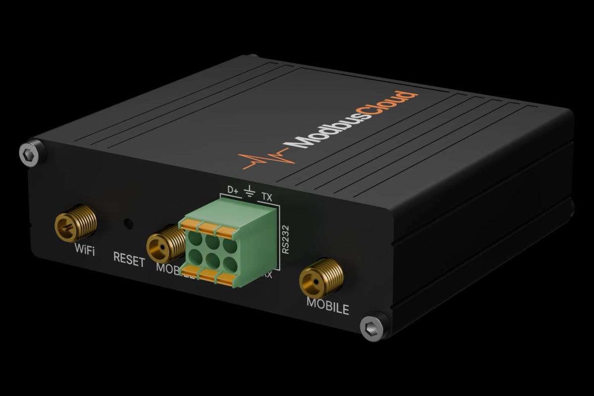
Connect the ModbusCloud Gateway RS485 A and B to SG+ and SG- on the RJ45 port of the drive, and terminate the end of the bus.
On the drive set Pr.09.00 to the Modbus address, Pr.09.01 to 1 for 9600 bps and Pr.09.04 to 4 for RTU 8,E,1.
For remote control set Pr.02.00 to 3 for the frequency and Pr.02.01 to 3 or 4 for the run command.
In ModbusCloud add a Modbus device on the gateway, import the Delta VFD-E template and enter the same address.
Check that output frequency and drive status come in, then test a setpoint change at a safe moment.
Things to watch for
The drive does not answer at all. What should I check?
The VFD-E ships with Modbus ASCII as protocol. Set Pr.09.04 to an RTU setting that matches the gateway (4 is 8,E,1), Pr.09.01 to the same speed and Pr.09.00 to the address. Check SG+ and SG- against A and B, and the termination. VFD-E models with a C in the type code have CANopen instead of RS485.
Status values work but some parameters give errors. Why?
The drive answers parameter reads one register per request. If a block of parameters fails while the 2100H status values are fine, read those parameters as single registers or remove the ones you do not need from the device.
Why does writing the frequency setpoint not change the speed?
The drive only follows the communication setpoint when Pr.02.00 is 3, and only follows the run command when Pr.02.01 is 3 or 4. Changes to parameters are stored, so avoid writing the same value in a fast loop.
Acceleration times show ten times too high or too low. What is wrong?
Pr.01.19 sets the time unit. With 0 (factory) one count is 0.1 s, with 1 it is 0.01 s. The template assumes 0.1 s; with 0.01 s, divide the shown value by ten or change the scale in the portal.
More Delta templates


Want to see how it works?