

Endress+Hauser Proline Promass 300
Coriolis flowmeter that measures mass flow, volume flow, density and temperature of liquids and gases.
The Endress+Hauser Proline Promass 300 is a Coriolis flowmeter that measures mass flow, density and temperature of liquids and gases directly in the pipe. This Modbus RTU template reads flow, density, temperature, totalizers and diagnostics, and lets you change units, damping, low flow cut off and totalizer settings from ModbusCloud.
- Protocol
- Modbus RTU
- Connection
- RS485, 19200 baud
- Registers
- 655, read and write
- Brand
- Endress+Hauser
- Key readings
- Mass flow · Volume flow · Density · Temperature · Totalizers · Diagnostic messages · Corrected volume flow
- Available commands
- Engineering units · Damping · Low flow cut off · Totalizer reset · Output settings
- Compatible models
- Promass A 300 · Promass E 300 · Promass F 300 · Promass H 300 · Promass I 300 · Promass O 300 · Promass P 300 · Promass Q 300 · Promass S 300 · Promass X 300
- Last updated
Registers (655)
655 read, 446 write
| Name | Unit | Access | Address (Hidden until you enter your email) | Function (hidden) | Type (hidden) |
|---|---|---|---|---|---|
| Mass Flow | kg/h | Read | |||
| Volume Flow | l/h | Read | |||
| Corrected Volume Flow | Read | ||||
| Density | Read | ||||
| Reference Density | Read | ||||
| Temperature | °C | Read | |||
| Pressure | bar | Read | |||
| Dynamic Viscosity | Read | ||||
| Kinematic Viscosity | Read | ||||
| Temp. Compensated Dynamic Viscosity | Read | ||||
| Temp. Compensated Kinematic Viscosity | Read | ||||
| Concentration | Read | ||||
| Target Mass Flow | Read | ||||
| Carrier Mass Flow | Read | ||||
| Target Corrected Volume Flow | Read | ||||
| Carrier Corrected Volume Flow | Read | ||||
| Target Volume Flow | Read | ||||
| Carrier Volume Flow | Read | ||||
| CTL | Read | ||||
| CPL | Read | ||||
| CTPL | Read | ||||
| S&W Volume Flow | Read | ||||
| S&W Correction Value | Read | ||||
| Reference Density Alternative | Read | ||||
| GSV Flow | Read | ||||
| GSV Flow Alternative | Read | ||||
| NSV Flow | Read | ||||
| NSV Flow Alternative | Read | ||||
| Oil CTL | Read | ||||
| Oil CPL | Read | ||||
| Oil CTPL | Read | ||||
| Water CTL | Read | ||||
| CTL Alternative | Read | ||||
| CPL Alternative | Read | ||||
| Oil Reference Density | Read | ||||
| Water Reference Density | Read | ||||
| Oil Density | Read | ||||
| Water Density | Read | ||||
| Water Cut | % | Read | |||
| Oil Volume Flow | Read | ||||
| Oil Corrected Volume Flow | Read | ||||
| Oil Mass Flow | Read | ||||
| Water Volume Flow | Read | ||||
| Water Corrected Volume Flow | Read | ||||
| Water Mass Flow | Read | ||||
| Weighted Density Average | Read | ||||
| Weighted Temperature Average | Read | ||||
| Time Period Signal (TPS) | Read | ||||
| Time Period Signal Frequency (TPS) | Hz | Read | |||
| Totalizer Value 1 | Read | ||||
| Totalizer Value 2 | Read | ||||
| Totalizer Value 3 | Read | ||||
| Totalizer Overflow 1 | Read | ||||
| Totalizer Overflow 2 | Read | ||||
| Totalizer Overflow 3 | Read | ||||
| Measured Values 1 | Read | ||||
| Measured Values 2 | Read | ||||
| Measured Values 3 | Read | ||||
| Current Input 1 Measured Current | mA | Read | |||
| Current Input 2 Measured Current | mA | Read | |||
| Current Input 3 Measured Current | mA | Read | |||
| Value Status Input 1 | Read | ||||
| Value Status Input 2 | Read | ||||
| Value Status Input 3 | Read | ||||
| Output Current 1 | mA | Read | |||
| Output Current 2 | mA | Read | |||
| Output Current 3 | mA | Read | |||
| Value Current Output 1 Measured Current | mA | Read | |||
| Value Current Output 2 Measured Current | mA | Read | |||
| Value Current Output 3 Measured Current | mA | Read | |||
| Output Frequency 1 | Hz | Read | |||
| Output Frequency 2 | Hz | Read | |||
| Output Frequency 3 | Hz | Read | |||
| Pulse Output 1 | Read | ||||
| Pulse Output 2 | Read | ||||
| Pulse Output 3 | Read | ||||
| Pulse/frequency/switch Output 1 Switch State | Read | ||||
| Pulse/frequency/switch Output 2 Switch State | Read | ||||
| Pulse/frequency/switch Output 3 Switch State | Read | ||||
| Relay Output 1 Switch State | Read | ||||
| Relay Output 2 Switch State | Read | ||||
| Relay Output 3 Switch State | Read | ||||
| Switch Cycles 1 | Read | ||||
| Switch Cycles 2 | Read | ||||
| Switch Cycles 3 | Read | ||||
| Max. Switch Cycles Number 1 | Read | ||||
| Max. Switch Cycles Number 2 | Read | ||||
| Max. Switch Cycles Number 3 | Read | ||||
| Pulse Output | Read | ||||
| Actual Diagnostics | Read | ||||
| Previous Diagnostics | Read | ||||
| Operating Time From Restart | Read | ||||
| Diagnostics 1 | Read | ||||
| Diagnostics 2 | Read | ||||
| Diagnostics 3 | Read | ||||
| Diagnostics 4 | Read | ||||
| Diagnostics 5 | Read | ||||
| Filter Options | Read and write | ||||
| Device Tag | Read | ||||
| Serial Number | Read | ||||
| Device Information Firmware Version | Read | ||||
| Device Name | Read | ||||
| Order Code | Read | ||||
| Extended Order Code 1 | Read | ||||
| Extended Order Code 2 | Read | ||||
| Extended Order Code 3 | Read | ||||
| ENP Version | Read | ||||
| Main Electronic Module + I/O Module 1 Firmware Version | Read | ||||
| Build No. Software | Read | ||||
| Bootloader Revision | Read | ||||
| Assign Channel 1 | Read and write | ||||
| Assign Channel 2 | Read and write | ||||
| Assign Channel 3 | Read and write | ||||
| Assign Channel 4 | Read and write | ||||
| Logging Interval | s | Read and write | |||
| Clear Logging Data | Read and write | ||||
| Data Logging | Read and write | ||||
| Logging Delay | h | Read and write | |||
| Data Logging Control | Read and write | ||||
| Data Logging Status | Read | ||||
| Entire Logging Duration | Read | ||||
| Reset Min/max Values | Read and write | ||||
| Electronics Temperature Minimum Value | Read | ||||
| Electronics Temperature Maximum Value | Read | ||||
| Medium Temperature Minimum Value | Read | ||||
| Medium Temperature Maximum Value | Read | ||||
| Carrier Pipe Temperature Minimum Value | Read | ||||
| Carrier Pipe Temperature Maximum Value | Read | ||||
| Oscillation Frequency Minimum Value | Read | ||||
| Oscillation Frequency Maximum Value | Read | ||||
| Torsion Oscillation Frequency Minimum Value | Read | ||||
| Torsion Oscillation Frequency Maximum Value | Read | ||||
| Oscillation Amplitude Minimum Value | Read | ||||
| Oscillation Amplitude Maximum Value | Read | ||||
| Torsion Oscillation Amplitude Minimum Value | Read | ||||
| Torsion Oscillation Amplitude Maximum Value | Read | ||||
| Oscillation Damping Minimum Value | Read | ||||
| Oscillation Damping Maximum Value | Read | ||||
| Torsion Oscillation Damping Minimum Value | Read | ||||
| Torsion Oscillation Damping Maximum Value | Read | ||||
| Signal Asymmetry Minimum Value | Read | ||||
| Signal Asymmetry Maximum Value | Read | ||||
| Torsion Signal Asymmetry Minimum Value | Read | ||||
| Torsion Signal Asymmetry Maximum Value | Read | ||||
| Direct Access | Read and write | ||||
| Locking Status | Read | ||||
| User Role | Read | ||||
| Enter Access Code | Read and write | ||||
| Display Language | Read and write | ||||
| Format Display | Read and write | ||||
| Value 1 Display | Read and write | ||||
| 0% Bargraph Value 1 | Read and write | ||||
| 100% Bargraph Value 1 | Read and write | ||||
| Decimal Places 1 | Read and write | ||||
| Value 2 Display | Read and write | ||||
| Decimal Places 2 | Read and write | ||||
| Value 3 Display | Read and write | ||||
| 0% Bargraph Value 3 | Read and write | ||||
| 100% Bargraph Value 3 | Read and write | ||||
| Decimal Places 3 | Read and write | ||||
| Value 4 Display | Read and write | ||||
| Decimal Places 4 | Read and write | ||||
| Value 5 Display | Read and write | ||||
| Decimal Places 5 | Read and write | ||||
| Value 6 Display | Read and write | ||||
| Decimal Places 6 | Read and write | ||||
| Value 7 Display | Read and write | ||||
| Decimal Places 7 | Read and write | ||||
| Value 8 Display | Read and write | ||||
| Decimal Places 8 | Read and write | ||||
| Display Interval | s | Read and write | |||
| Display Damping | s | Read and write | |||
| Header | Read and write | ||||
| Header Text | Read and write | ||||
| Separator | Read and write | ||||
| Contrast Display | % | Read and write | |||
| Backlight | Read and write | ||||
| Operating Time | Read | ||||
| Last Backup | Read | ||||
| Configuration Management | Read and write | ||||
| Backup State | Read | ||||
| Comparison Result | Read | ||||
| Alarm Delay | s | Read and write | |||
| Assign Behavior of Diagnostic No. 046 | Read and write | ||||
| Assign Behavior of Diagnostic No. 140 | Read and write | ||||
| Assign Behavior of Diagnostic No. 144 | Read and write | ||||
| Assign Behavior of Diagnostic No. 374 | Read and write | ||||
| Assign Behavior of Diagnostic No. 302 | Read and write | ||||
| Assign Behavior of Diagnostic No. 862 | Read and write | ||||
| Assign Behavior of Diagnostic No. 912 | Read and write | ||||
| Assign Behavior of Diagnostic No. 913 | Read and write | ||||
| Assign Behavior of Diagnostic No. 941 | Read and write | ||||
| Assign Behavior of Diagnostic No. 942 | Read and write | ||||
| Assign Behavior of Diagnostic No. 943 | Read and write | ||||
| Assign Behavior of Diagnostic No. 944 | Read and write | ||||
| Assign Behavior of Diagnostic No. 948 | Read and write | ||||
| Assign Behavior of Diagnostic No. 984 | Read and write | ||||
| Assign Behavior of Diagnostic No. 441 | Read and write | ||||
| Assign Behavior of Diagnostic No. 442 | Read and write | ||||
| Assign Behavior of Diagnostic No. 443 | Read and write | ||||
| Assign Behavior of Diagnostic No. 444 | Read and write | ||||
| Assign Behavior of Diagnostic No. 543 | Read and write | ||||
| Assign Behavior of Diagnostic No. 599 | Read and write | ||||
| Assign Behavior of Diagnostic No. 830 | Read and write | ||||
| Assign Behavior of Diagnostic No. 831 | Read and write | ||||
| Assign Behavior of Diagnostic No. 832 | Read and write | ||||
| Assign Behavior of Diagnostic No. 833 | Read and write | ||||
| Assign Behavior of Diagnostic No. 834 | Read and write | ||||
| Assign Behavior of Diagnostic No. 835 | Read and write | ||||
| Assign Behavior of Diagnostic No. 842 | Read and write | ||||
| Device Reset | Read and write | ||||
| Transmitter Identifier | Read | ||||
| Activate SW Option | Read and write | ||||
| Software Option Overview | Read | ||||
| Define Access Code | Read and write | ||||
| Confirm Access Code | Read and write | ||||
| Reset Access Code | Read and write | ||||
| Mass Flow Unit | Read and write | ||||
| Mass Unit | Read and write | ||||
| Volume Flow Unit | Read and write | ||||
| Volume Unit | Read and write | ||||
| Corrected Volume Flow Unit | Read and write | ||||
| Corrected Volume Unit | Read and write | ||||
| Density Unit | Read and write | ||||
| Reference Density Unit | Read and write | ||||
| Density 2 Unit | Read and write | ||||
| Temperature Unit | Read and write | ||||
| Pressure Unit | Read and write | ||||
| Date/time Format | Read and write | ||||
| Flow Damping | s | Read and write | |||
| Density Damping | s | Read and write | |||
| Temperature Damping | s | Read and write | |||
| Flow Override | Read and write | ||||
| Low Flow Cut Off Assign Process Variable | Read and write | ||||
| On Value Low Flow Cutoff | Read and write | ||||
| Off Value Low Flow Cutoff | % | Read and write | |||
| Pressure Shock Suppression | s | Read and write | |||
| Partially Filled Pipe Detection Assign Process Variable | Read and write | ||||
| Low Value Partial Filled Pipe Detection | Read and write | ||||
| High Value Partial Filled Pipe Detection | Read and write | ||||
| Response Time Part. Filled Pipe Detect. | s | Read and write | |||
| Maximum Damping Partial Filled Pipe Det. | Read and write | ||||
| Select Reference Density | Read and write | ||||
| External Reference Density | Read | ||||
| Fixed Reference Density | Read and write | ||||
| Reference Temperature | °C | Read and write | |||
| Linear Expansion Coefficient | Read and write | ||||
| Square Expansion Coefficient | Read and write | ||||
| MFT (Multi-Frequency Technology) | Read and write | ||||
| Select Medium | Read and write | ||||
| Select Gas Type | Read and write | ||||
| Reference Sound Velocity | m/s | Read and write | |||
| Temperature Coefficient Sound Velocity | Read and write | ||||
| Gas Fraction Handler | Read and write | ||||
| Pressure Compensation | Read and write | ||||
| Pressure Value | Read and write | ||||
| External Pressure | Read and write | ||||
| Temperature Correction Source | Read and write | ||||
| External Temperature | Read and write | ||||
| Application Specific Input Source 0 | Read and write | ||||
| Application Specific Input Source 1 | Read and write | ||||
| Installation Direction | Read and write | ||||
| Installation Angle Roll | ° | Read and write | |||
| Installation Angle Pitch | ° | Read and write | |||
| Combined Density-pressure Factor | Read | ||||
| Combined Density-temperature Factor | Read | ||||
| Cubic Temperature Factor | Read | ||||
| Constant Offset | Read | ||||
| Linear Density Factor | Read | ||||
| Linear Temperature Factor | Read | ||||
| Linear Pressure Factor | Read | ||||
| Quadratic Density Factor | Read | ||||
| Quadratic Temperature Factor | Read | ||||
| Quadratic Pressure Factor | Read | ||||
| Combined Temperature-pressure Factor | Read | ||||
| Process Conditions | Read and write | ||||
| Progress | % | Read | |||
| Status | Read | ||||
| Advanced Information | Read and write | ||||
| Recommendation | Read | ||||
| Root Cause | Read | ||||
| Abort Message | Read | ||||
| Reliability of Measured Zero | Read | ||||
| Zero Point Measured | Read | ||||
| Select Action | Read and write | ||||
| Mass Flow Offset | Read and write | ||||
| Mass Flow Factor | Read and write | ||||
| Volume Flow Offset | Read and write | ||||
| Volume Flow Factor | Read and write | ||||
| Density Offset | Read and write | ||||
| Density Factor | Read and write | ||||
| Corrected Volume Flow Offset | Read and write | ||||
| Corrected Volume Flow Factor | Read and write | ||||
| Reference Density Offset | Read and write | ||||
| Reference Density Factor | Read and write | ||||
| Temperature Offset | Read and write | ||||
| Temperature Factor | Read and write | ||||
| Calibration Factor | Read | ||||
| Zero | Read and write | ||||
| Nominal Diameter | Read | ||||
| Calibration Coefficient C0 | Read | ||||
| Calibration Coefficient C1 | Read | ||||
| Calibration Coefficient C2 | Read | ||||
| Calibration Coefficient C3 | Read | ||||
| Calibration Coefficient C4 | Read | ||||
| Calibration Coefficient C5 | Read | ||||
| I/O Module 1 Terminal Numbers | Read | ||||
| I/O Module 2 Terminal Numbers | Read | ||||
| I/O Module 3 Terminal Numbers | Read | ||||
| I/O Module 4 Terminal Numbers | Read | ||||
| I/O Module 1 Information | Read | ||||
| I/O Module 2 Information | Read | ||||
| I/O Module 3 Information | Read | ||||
| I/O Module 4 Information | Read | ||||
| I/O Module 1 Type | Read and write | ||||
| I/O Module 2 Type | Read and write | ||||
| I/O Module 3 Type | Read and write | ||||
| I/O Module 4 Type | Read and write | ||||
| Apply I/O Configuration | Read and write | ||||
| I/O Alteration Code | Read and write | ||||
| Current Input 1 Terminal Number | Read | ||||
| Current Input 2 Terminal Number | Read | ||||
| Current Input 3 Terminal Number | Read | ||||
| Current Input 1 Signal Mode | Read and write | ||||
| Current Input 2 Signal Mode | Read and write | ||||
| Current Input 3 Signal Mode | Read and write | ||||
| Current Span 1 | Read and write | ||||
| Current Span 2 | Read and write | ||||
| Current Span 3 | Read and write | ||||
| 0/4 mA Value 1 | Read and write | ||||
| 0/4 mA Value 2 | Read and write | ||||
| 0/4 mA Value 3 | Read and write | ||||
| 20 mA Value 1 | Read and write | ||||
| 20 mA Value 2 | Read and write | ||||
| 20 mA Value 3 | Read and write | ||||
| Current Input 1 Failure Mode | Read and write | ||||
| Current Input 2 Failure Mode | Read and write | ||||
| Current Input 3 Failure Mode | Read and write | ||||
| Failure Value 1 | Read and write | ||||
| Failure Value 2 | Read and write | ||||
| Failure Value 3 | Read and write | ||||
| Status Input 1 Terminal Number | Read | ||||
| Status Input 2 Terminal Number | Read | ||||
| Status Input 3 Terminal Number | Read | ||||
| Assign Status Input 1 | Read and write | ||||
| Assign Status Input 2 | Read and write | ||||
| Assign Status Input 3 | Read and write | ||||
| Active Level 1 | Read and write | ||||
| Active Level 2 | Read and write | ||||
| Active Level 3 | Read and write | ||||
| Response Time Status Input 1 | ms | Read and write | |||
| Response Time Status Input 2 | ms | Read and write | |||
| Response Time Status Input 3 | ms | Read and write | |||
| Current Output 1 Terminal Number | Read | ||||
| Current Output 2 Terminal Number | Read | ||||
| Current Output 3 Terminal Number | Read | ||||
| Current Output 1 Signal Mode | Read and write | ||||
| Current Output 2 Signal Mode | Read and write | ||||
| Current Output 3 Signal Mode | Read and write | ||||
| Process Variable Current Output 1 | Read and write | ||||
| Process Variable Current Output 2 | Read and write | ||||
| Process Variable Current Output 3 | Read and write | ||||
| Current Range Output 1 | Read and write | ||||
| Current Range Output 2 | Read and write | ||||
| Current Range Output 3 | Read and write | ||||
| Fixed Current 1 | mA | Read and write | |||
| Fixed Current 2 | mA | Read and write | |||
| Fixed Current 3 | mA | Read and write | |||
| Lower Range Value Output 1 | Read and write | ||||
| Lower Range Value Output 2 | Read and write | ||||
| Lower Range Value Output 3 | Read and write | ||||
| Upper Range Value Output 1 | Read and write | ||||
| Upper Range Value Output 2 | Read and write | ||||
| Upper Range Value Output 3 | Read and write | ||||
| Measuring Mode Current Output 1 | Read and write | ||||
| Measuring Mode Current Output 2 | Read and write | ||||
| Measuring Mode Current Output 3 | Read and write | ||||
| Damping Current Output 1 | s | Read and write | |||
| Damping Current Output 2 | s | Read and write | |||
| Damping Current Output 3 | s | Read and write | |||
| Failure Behavior Current Output 1 | Read and write | ||||
| Failure Behavior Current Output 2 | Read and write | ||||
| Failure Behavior Current Output 3 | Read and write | ||||
| Failure Current 1 | mA | Read and write | |||
| Failure Current 2 | mA | Read and write | |||
| Failure Current 3 | mA | Read and write | |||
| Pulse/frequency/switch Output 1 Terminal Number | Read | ||||
| Pulse/frequency/switch Output 2 Terminal Number | Read | ||||
| Pulse/frequency/switch Output 3 Terminal Number | Read | ||||
| Pulse/frequency/switch Output 1 Signal Mode | Read and write | ||||
| Pulse/frequency/switch Output 2 Signal Mode | Read and write | ||||
| Pulse/frequency/switch Output 3 Signal Mode | Read and write | ||||
| Operating Mode 1 | Read and write | ||||
| Operating Mode 2 | Read and write | ||||
| Operating Mode 3 | Read and write | ||||
| Pulse/frequency/switch Output 1 Assign Pulse Output | Read and write | ||||
| Assign Pulse Output 2 | Read and write | ||||
| Assign Pulse Output 3 | Read and write | ||||
| Pulse Scaling 1 | Read and write | ||||
| Pulse Scaling 2 | Read and write | ||||
| Pulse Scaling 3 | Read and write | ||||
| Pulse Width 1 | ms | Read and write | |||
| Pulse Width 2 | ms | Read and write | |||
| Pulse Width 3 | ms | Read and write | |||
| Pulse/frequency/switch Output 1 Pulse Measuring Mode | Read and write | ||||
| Pulse/frequency/switch Output 2 Pulse Measuring Mode | Read and write | ||||
| Pulse/frequency/switch Output 3 Pulse Measuring Mode | Read and write | ||||
| Pulse/frequency/switch Output 1 Pulse Failure Mode | Read and write | ||||
| Pulse/frequency/switch Output 2 Pulse Failure Mode | Read and write | ||||
| Pulse/frequency/switch Output 3 Pulse Failure Mode | Read and write | ||||
| Assign Frequency Output 1 | Read and write | ||||
| Assign Frequency Output 2 | Read and write | ||||
| Assign Frequency Output 3 | Read and write | ||||
| Minimum Frequency Value 1 | Hz | Read and write | |||
| Minimum Frequency Value 2 | Hz | Read and write | |||
| Minimum Frequency Value 3 | Hz | Read and write | |||
| Maximum Frequency Value 1 | Hz | Read and write | |||
| Maximum Frequency Value 2 | Hz | Read and write | |||
| Maximum Frequency Value 3 | Hz | Read and write | |||
| Measuring Value at Minimum Frequency 1 | Read and write | ||||
| Measuring Value at Minimum Frequency 2 | Read and write | ||||
| Measuring Value at Minimum Frequency 3 | Read and write | ||||
| Measuring Value at Maximum Frequency 1 | Read and write | ||||
| Measuring Value at Maximum Frequency 2 | Read and write | ||||
| Measuring Value at Maximum Frequency 3 | Read and write | ||||
| Pulse/frequency/switch Output 1 Frequency Measuring Mode | Read and write | ||||
| Pulse/frequency/switch Output 2 Frequency Measuring Mode | Read and write | ||||
| Pulse/frequency/switch Output 3 Frequency Measuring Mode | Read and write | ||||
| Damping Output 1 | s | Read and write | |||
| Damping Output 2 | s | Read and write | |||
| Damping Output 3 | s | Read and write | |||
| Pulse/frequency/switch Output 1 Frequency Failure Mode | Read and write | ||||
| Pulse/frequency/switch Output 2 Frequency Failure Mode | Read and write | ||||
| Pulse/frequency/switch Output 3 Frequency Failure Mode | Read and write | ||||
| Failure Frequency 1 | Hz | Read and write | |||
| Failure Frequency 2 | Hz | Read and write | |||
| Failure Frequency 3 | Hz | Read and write | |||
| Switch Output Function 1 | Read and write | ||||
| Switch Output Function 2 | Read and write | ||||
| Switch Output Function 3 | Read and write | ||||
| Pulse/frequency/switch Output 1 Assign Diagnostic Behavior | Read and write | ||||
| Pulse/frequency/switch Output 2 Assign Diagnostic Behavior | Read and write | ||||
| Pulse/frequency/switch Output 3 Assign Diagnostic Behavior | Read and write | ||||
| Pulse/frequency/switch Output 1 Assign Limit | Read and write | ||||
| Pulse/frequency/switch Output 2 Assign Limit | Read and write | ||||
| Pulse/frequency/switch Output 3 Assign Limit | Read and write | ||||
| Pulse/frequency/switch Output 1 Switch-on Value | Read and write | ||||
| Pulse/frequency/switch Output 2 Switch-on Value | Read and write | ||||
| Pulse/frequency/switch Output 3 Switch-on Value | Read and write | ||||
| Pulse/frequency/switch Output 1 Switch-off Value | Read and write | ||||
| Pulse/frequency/switch Output 2 Switch-off Value | Read and write | ||||
| Pulse/frequency/switch Output 3 Switch-off Value | Read and write | ||||
| Pulse/frequency/switch Output 1 Assign Flow Direction Check | Read and write | ||||
| Pulse/frequency/switch Output 2 Assign Flow Direction Check | Read and write | ||||
| Pulse/frequency/switch Output 3 Assign Flow Direction Check | Read and write | ||||
| Pulse/frequency/switch Output 1 Assign Status | Read and write | ||||
| Pulse/frequency/switch Output 2 Assign Status | Read and write | ||||
| Pulse/frequency/switch Output 3 Assign Status | Read and write | ||||
| Pulse/frequency/switch Output 1 Switch-on Delay | s | Read and write | |||
| Pulse/frequency/switch Output 2 Switch-on Delay | s | Read and write | |||
| Pulse/frequency/switch Output 3 Switch-on Delay | s | Read and write | |||
| Pulse/frequency/switch Output 1 Switch-off Delay | s | Read and write | |||
| Pulse/frequency/switch Output 2 Switch-off Delay | s | Read and write | |||
| Pulse/frequency/switch Output 3 Switch-off Delay | s | Read and write | |||
| Pulse/frequency/switch Output 1 Switch Failure Mode | Read and write | ||||
| Pulse/frequency/switch Output 2 Switch Failure Mode | Read and write | ||||
| Pulse/frequency/switch Output 3 Switch Failure Mode | Read and write | ||||
| Invert Output Signal 1 | Read and write | ||||
| Invert Output Signal 2 | Read and write | ||||
| Invert Output Signal 3 | Read and write | ||||
| Relay Output 1 Terminal Number | Read | ||||
| Relay Output 2 Terminal Number | Read | ||||
| Relay Output 3 Terminal Number | Read | ||||
| Relay Output Function 1 | Read and write | ||||
| Relay Output Function 2 | Read and write | ||||
| Relay Output Function 3 | Read and write | ||||
| Relay Output 1 Assign Flow Direction Check | Read and write | ||||
| Relay Output 2 Assign Flow Direction Check | Read and write | ||||
| Relay Output 3 Assign Flow Direction Check | Read and write | ||||
| Relay Output 1 Assign Limit | Read and write | ||||
| Relay Output 2 Assign Limit | Read and write | ||||
| Relay Output 3 Assign Limit | Read and write | ||||
| Relay Output 1 Assign Diagnostic Behavior | Read and write | ||||
| Relay Output 2 Assign Diagnostic Behavior | Read and write | ||||
| Relay Output 3 Assign Diagnostic Behavior | Read and write | ||||
| Relay Output 1 Assign Status | Read and write | ||||
| Relay Output 2 Assign Status | Read and write | ||||
| Relay Output 3 Assign Status | Read and write | ||||
| Relay Output 1 Switch-off Value | Read and write | ||||
| Relay Output 2 Switch-off Value | Read and write | ||||
| Relay Output 3 Switch-off Value | Read and write | ||||
| Relay Output 1 Switch-off Delay | s | Read and write | |||
| Relay Output 2 Switch-off Delay | s | Read and write | |||
| Relay Output 3 Switch-off Delay | s | Read and write | |||
| Relay Output 1 Switch-on Value | Read and write | ||||
| Relay Output 2 Switch-on Value | Read and write | ||||
| Relay Output 3 Switch-on Value | Read and write | ||||
| Relay Output 1 Switch-on Delay | s | Read and write | |||
| Relay Output 2 Switch-on Delay | s | Read and write | |||
| Relay Output 3 Switch-on Delay | s | Read and write | |||
| Relay Output 1 Failure Mode | Read and write | ||||
| Relay Output 2 Failure Mode | Read and write | ||||
| Relay Output 3 Failure Mode | Read and write | ||||
| Powerless Relay Status 1 | Read and write | ||||
| Powerless Relay Status 2 | Read and write | ||||
| Powerless Relay Status 3 | Read and write | ||||
| Master Terminal Number | Read | ||||
| Slave Terminal Number | Read | ||||
| Signal Mode | Read and write | ||||
| Double Pulse Output Assign Pulse Output 1 | Read and write | ||||
| Value per Pulse | Read and write | ||||
| Pulse Width | ms | Read and write | |||
| Phase Shift | Read and write | ||||
| Measuring Mode | Read and write | ||||
| Double Pulse Output Failure Mode | Read and write | ||||
| Invert Output Signal | Read and write | ||||
| Bus Address | Read and write | ||||
| Baudrate | Read and write | ||||
| Data Transfer Mode | Read and write | ||||
| Parity | Read and write | ||||
| Byte Order | Read and write | ||||
| Telegram Delay | ms | Read and write | |||
| Modbus Configuration Failure Mode | Read and write | ||||
| Bus Termination | Read | ||||
| Fieldbus Writing Access | Read and write | ||||
| Device ID | Read | ||||
| Device Revision | Read | ||||
| Scan List Register 0 | Read and write | ||||
| Scan List Register 1 | Read and write | ||||
| Scan List Register 2 | Read and write | ||||
| Scan List Register 3 | Read and write | ||||
| Scan List Register 4 | Read and write | ||||
| Scan List Register 5 | Read and write | ||||
| Scan List Register 6 | Read and write | ||||
| Scan List Register 7 | Read and write | ||||
| Scan List Register 8 | Read and write | ||||
| Scan List Register 9 | Read and write | ||||
| Scan List Register 10 | Read and write | ||||
| Scan List Register 11 | Read and write | ||||
| Scan List Register 12 | Read and write | ||||
| Scan List Register 13 | Read and write | ||||
| Scan List Register 14 | Read and write | ||||
| Scan List Register 15 | Read and write | ||||
| Web Server Language | Read and write | ||||
| MAC Address | Read | ||||
| DHCP Client | Read and write | ||||
| IP Address | Read and write | ||||
| Subnet Mask | Read and write | ||||
| Default Gateway | Read and write | ||||
| Web Server Functionality | Read and write | ||||
| Login Page | Read and write | ||||
| WLAN | Read and write | ||||
| WLAN Mode | Read and write | ||||
| WLAN SSID Name (Parameter 2714) | Read and write | ||||
| Network Security | Read and write | ||||
| Security Identification | Read | ||||
| User Name | Read and write | ||||
| WLAN Password | Read and write | ||||
| WLAN IP Address | Read and write | ||||
| WLAN MAC Address | Read | ||||
| WLAN Subnet Mask | Read and write | ||||
| WLAN Passphrase | Read and write | ||||
| WLAN SSID Name (Parameter 2708) | Read and write | ||||
| WLAN SSID Name (Parameter 2707) | Read and write | ||||
| 2.4 GHz WLAN Channel | Read and write | ||||
| Select Antenna | Read and write | ||||
| Connection State | Read | ||||
| Received Signal Strength | Read | ||||
| Gateway IP Address | Read | ||||
| IP Address Domain Name Server | Read | ||||
| Reset All Totalizers | Read and write | ||||
| Assign Process Variable 1 | Read and write | ||||
| Assign Process Variable 2 | Read and write | ||||
| Assign Process Variable 3 | Read and write | ||||
| Unit Totalizer 1 | Read and write | ||||
| Unit Totalizer 2 | Read and write | ||||
| Unit Totalizer 3 | Read and write | ||||
| Totalizer Operation Mode 1 | Read and write | ||||
| Totalizer Operation Mode 2 | Read and write | ||||
| Totalizer Operation Mode 3 | Read and write | ||||
| Control Totalizer 1 | Read and write | ||||
| Control Totalizer 2 | Read and write | ||||
| Control Totalizer 3 | Read and write | ||||
| Preset Value 1 | Read and write | ||||
| Preset Value 2 | Read and write | ||||
| Preset Value 3 | Read and write | ||||
| Totalizer 1 Failure Mode | Read and write | ||||
| Totalizer 2 Failure Mode | Read and write | ||||
| Totalizer 3 Failure Mode | Read and write | ||||
| Parameter 0 | Read and write | ||||
| Parameter 1 | Read and write | ||||
| Parameter 2 | Read and write | ||||
| Parameter 3 | Read and write | ||||
| Parameter 4 | Read and write | ||||
| Parameter 5 | Read and write | ||||
| Parameter 6 | Read and write | ||||
| Parameter 7 | Read and write | ||||
| Parameter 8 | Read and write | ||||
| Parameter 9 | Read and write | ||||
| Application Specific Input 0 | Read | ||||
| Application Specific Input 1 | Read | ||||
| Application Specific Output 0 | Read | ||||
| Application Specific Output 1 | Read | ||||
| Index Inhomogeneous Medium | Read | ||||
| Cut Off Inhomogeneous Wet Gas | Read and write | ||||
| Cut Off Inhomogeneous Liquid | Read and write | ||||
| Index Suspended Bubbles | Read | ||||
| Cut Off Suspended Bubbles | Read and write | ||||
| Assign Simulation Process Variable | Read and write | ||||
| Process Variable Value | Read and write | ||||
| Current Output 1 Simulation | Read and write | ||||
| Current Output 2 Simulation | Read and write | ||||
| Current Output 3 Simulation | Read and write | ||||
| Current Output Value | mA | Read and write | |||
| Frequency Output 1 Simulation | Read and write | ||||
| Frequency Output 2 Simulation | Read and write | ||||
| Frequency Output 3 Simulation | Read and write | ||||
| Frequency Output 1 Value | Hz | Read and write | |||
| Frequency Output 2 Value | Hz | Read and write | |||
| Frequency Output 3 Value | Hz | Read and write | |||
| Pulse Output Simulation 1 | Read and write | ||||
| Pulse Output Simulation 2 | Read and write | ||||
| Pulse Output Simulation 3 | Read and write | ||||
| Pulse Value 1 | Read and write | ||||
| Pulse Value 2 | Read and write | ||||
| Pulse Value 3 | Read and write | ||||
| Switch Output Simulation 1 | Read and write | ||||
| Switch Output Simulation 2 | Read and write | ||||
| Switch Output Simulation 3 | Read and write | ||||
| Switch Output 1 Simulated State | Read and write | ||||
| Switch Output 2 Simulated State | Read and write | ||||
| Switch Output 3 Simulated State | Read and write | ||||
| Relay Output 1 Simulation | Read and write | ||||
| Relay Output 2 Simulation | Read and write | ||||
| Relay Output 3 Simulation | Read and write | ||||
| Relay Output 1 Simulated State | Read and write | ||||
| Relay Output 2 Simulated State | Read and write | ||||
| Relay Output 3 Simulated State | Read and write | ||||
| Pulse Output Simulation | Read and write | ||||
| Pulse Value | Read and write | ||||
| Device Alarm Simulation | Read and write | ||||
| Diagnostic Event Category | Read and write | ||||
| Diagnostic Event Simulation | Read and write | ||||
| Current Input 1 Simulation | Read and write | ||||
| Current Input 2 Simulation | Read and write | ||||
| Current Input 3 Simulation | Read and write | ||||
| Value Current Input 1 | mA | Read and write | |||
| Value Current Input 2 | mA | Read and write | |||
| Value Current Input 3 | mA | Read and write | |||
| Status Input 1 Simulation | Read and write | ||||
| Status Input 2 Simulation | Read and write | ||||
| Status Input 3 Simulation | Read and write | ||||
| Input Signal Level 1 | Read and write | ||||
| Input Signal Level 2 | Read and write | ||||
| Input Signal Level 3 | Read and write |
Loading registers…
Send your device list
If a device is not in the library yet, we build the template for free as soon as we have the register data.
Use cases
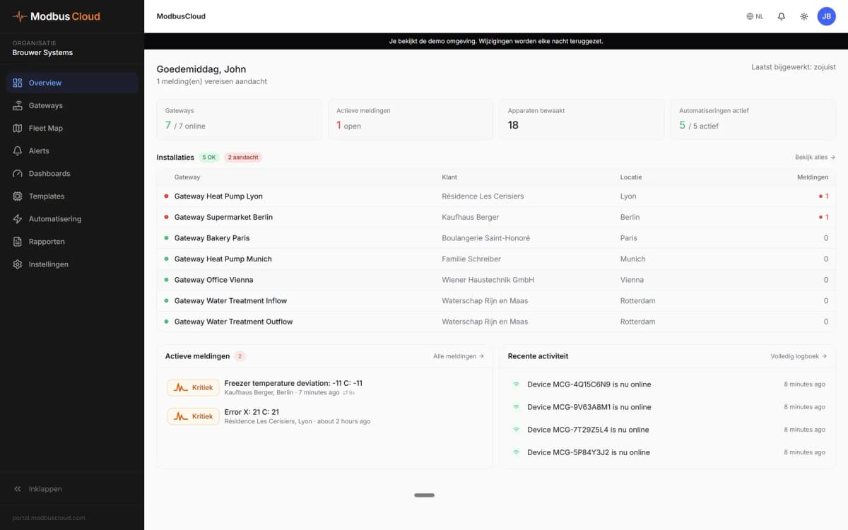
- Show mass flow, density and temperature on a dashboard per production line.
- Log totalizer values every day to report consumption per batch or per month.
- Raise an email alarm when the actual diagnostic code is not zero.
- Alert when density leaves its normal band, a sign of air or a wrong product in the line.
- Change the mass flow unit or the damping remotely without opening the transmitter.
- Compare electronics temperature and Heartbeat results over a year of history.
Installation
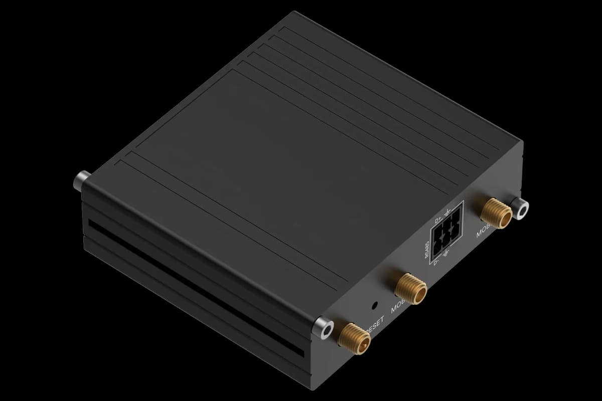
Connect RS485 A and B of the Modbus I/O module to the RS485 port of the ModbusCloud Gateway, and terminate both ends of the bus.
On the device, check under Communication that the bus address, 19200 baud, even parity and byte order 1-0-3-2 are set.
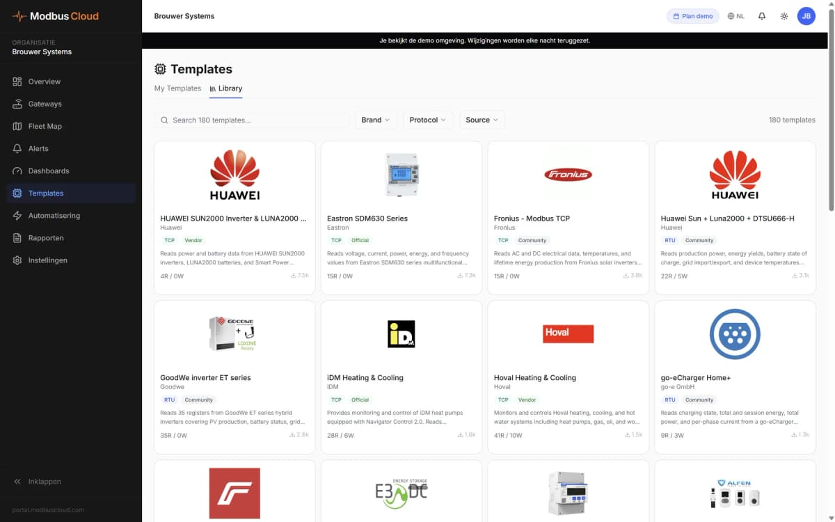
In ModbusCloud, add a Modbus device with the same address and serial settings and import this template.
Check that mass flow and temperature show plausible values; a zero flow at a running pump points to the wrong address or byte order.
Things to watch for
The flowmeter does not answer. What should I check?
Check the address (factory 247), 19200 baud and even parity on both sides, then swap A and B. Make sure the bus is terminated at both ends and that only one master polls the device.
Why do the flow values look like huge or tiny random numbers?
The float word order does not match. With the factory byte order 1-0-3-2 the template reads correctly. If someone changed the byte order on the device, set it back under Communication.
Some registers always read zero. Is that a fault?
Not always. Values such as concentration, viscosity, pressure or the petroleum values only exist with the matching order option or configuration. Without that option the device returns zero or rejects the read.
Is it safe to write settings from the portal?
Yes, but sparingly. Every write to a setting is stored in the EEPROM of the device, which allows about one million write cycles. Do not write settings from an automation that runs every few minutes, and check the access code if the device refuses writes.
More Endress+Hauser templates


Want to see how it works?