








Grundfos SMART Digital DDA
Monitors and controls Grundfos DDA dosing pumps: dosing flow, backpressure, dosed volume, tank level and alarms.
The Grundfos SMART Digital DDA is a digital dosing pump that doses acid, nutrients or disinfectant into water, for example into the irrigation water of a greenhouse. This Modbus RTU template reads dosing flow, backpressure, dosed volume, tank level and alarm codes and lets you write start and stop, the operating mode and the dosing setpoint from ModbusCloud.
- Protocol
- Modbus RTU
- Connection
- RS485, 19200 baud
- Registers
- 84, read and write
- Brand
- Grundfos
- Key readings
- Dosing flow · Backpressure · Dosed volume · Tank level · Operating mode and state · Alarm and warning code · Stroke counter · Process flow and concentration
- Available commands
- Start and stop · Operating mode · Manual dosing setpoint · Batch volume and time · Pressure alarm limit · Relay and analog outputs
- Compatible models
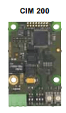
- SMART Digital S DDA model C · SMART Digital XL DDA · SoftCIM Modbus RTU (DDA model C) · SoftCIM Modbus TCP (DDA model C) · CIM 200 Modbus RTU in CIU 900 · CIM 500 Modbus TCP in CIU 900
- Last updated
Registers (84)
84 read, 25 write
| Name | Unit | Access | Address (Hidden until you enter your email) | Function (hidden) | Type (hidden) |
|---|---|---|---|---|---|
| Measured Dosing Capacity | l/h | Read | |||
| Dosing Capacity Reference | l/h | Read | |||
| Measured Pressure | bar | Read | |||
| Volume Total | l | Read | |||
| Volume Trip Counter | l | Read | |||
| Remaining Dosing Volume | l | Read | |||
| Tank Level Remaining | % | Read | |||
| Tank Volume Remaining | l | Read | |||
| Tank Volume | l | Read | |||
| Process Flow | l/h | Read | |||
| Actual Concentration | ppm | Read | |||
| Target Concentration | ppm | Read | |||
| Analog Input | mA | Read | |||
| Analog Output | mA | Read | |||
| Pulse Input Frequency | Read | ||||
| Actual Start Stop | Read | ||||
| Actual Operating Mode | Read | ||||
| Fault Code | Read | ||||
| Warning Code | Read | ||||
| Warning Bits | Read | ||||
| Miscellaneous Status Bits | Read | ||||
| Mode Status Bits | Read | ||||
| Function Enable Status Bits | Read | ||||
| Command Acknowledge Bits | Read | ||||
| Control Source States | Read | ||||
| Digital Inputs | Read | ||||
| Output Relays | Read | ||||
| Tank Level Monitoring | Read | ||||
| Actual Manual Setpoint | l/h | Read | |||
| Actual Pulse Volume | Read | ||||
| Actual Batch Dosing Volume | l | Read | |||
| Actual Batch Dosing Time | s | Read | |||
| Actual Pressure Max | bar | Read | |||
| Mode Control Bits | Read and write | ||||
| Function Enable Bits | Read and write | ||||
| Action Commands | Read and write | ||||
| Start Stop Request | Read and write | ||||
| Set Operating Mode | Read and write | ||||
| Set Manual Setpoint | l/h | Read and write | |||
| Set Pulse Volume | Read and write | ||||
| Set Batch Dosing Volume | l | Read and write | |||
| Set Batch Dosing Time | s | Read and write | |||
| Set Pressure Max | bar | Read and write | |||
| Set Target Concentration | ppm | Read and write | |||
| Set Output Relays | Read and write | ||||
| Set Analog Output | mA | Read and write | |||
| Set Clock Year | Read and write | ||||
| Set Clock Month | Read and write | ||||
| Set Clock Day | Read and write | ||||
| Set Clock Hour | Read and write | ||||
| Set Clock Minute | Read and write | ||||
| Set Clock Second | Read and write | ||||
| Dosing Capacity Max | l/h | Read | |||
| Dosing Pressure Max | bar | Read | |||
| Tank Volume Low Limit | l | Read | |||
| Tank Level Low Limit | % | Read | |||
| Process Flow Sensor Max | l/h | Read | |||
| Process Flow Pulse Volume | Read | ||||
| Operating Hours | s | Read | |||
| Run Time | Read | ||||
| Stroke Counter | Read | ||||
| Number Of Power Ons | Read | ||||
| Time To Next Dosing | s | Read | |||
| Clock Year | Read | ||||
| Clock Month | Read | ||||
| Clock Day | Read | ||||
| Clock Hour | Read | ||||
| Clock Minute | Read | ||||
| Clock Second | Read | ||||
| Auto Ack Control Bits | Read and write | ||||
| Slave Minimum Reply Delay | ms | Read and write | |||
| Software Defined Modbus Address | Read and write | ||||
| Software Defined Bit Rate | Read and write | ||||
| Software Defined Parity | Read and write | ||||
| Software Defined Stop Bits | Read and write | ||||
| Actual Modbus Address | Read | ||||
| CIM Version Number | Read | ||||
| GENIbus CRC Error Count | Read | ||||
| GENIbus Data Error Count | Read | ||||
| GENIbus TX Count | Read | ||||
| GENIbus RX Count | Read | ||||
| Unit Family | Read | ||||
| Unit Type | Read | ||||
| Unit Version | Read |
Loading registers…
Send your device list
If a device is not in the library yet, we build the template for free as soon as we have the register data.
Use cases
- Show dosing flow, backpressure and tank level of every dosing pump in the water room on one dashboard.
- Get an email or webhook alert when the pump reports a fault code, such as an empty tank, a blocked pump or too high pressure.
- Set a threshold on the remaining tank level so you refill the acid or nutrient tank before it runs empty.
- Follow the dosed volume over 365 days of history to check chemical consumption per week or season.
- Change the manual dosing setpoint or operating mode from the portal, or stop the pump with a scheduled automation.
- Compare measured dosing flow with the setpoint over time to see when the pump no longer reaches its setpoint.
Installation
DDA model C: in Grundfos GO or the pump menu, open Settings, Communication, RS485 AYB, select Modbus RTU and set address, baud rate, parity and stop bits.
DDA XL: fit a CIM 200 in a CIU 900, set the speed with SW4 and SW5 and the parity with SW3 (default 19200 baud, even parity, 1 stop bit), and choose the Modbus address in the pump menu.
Connect A and B (on the CIM 200: D1 positive, D0 negative) to the RS485 lines of the ModbusCloud Gateway with screened twisted pair, and terminate the bus only at both ends.
In ModbusCloud, add a Modbus device with the same address, speed, parity and stop bits, and import this template.
Check that Unit Family reads 30 and that Dosing Capacity Reference matches the pump display. If nothing answers, swap A and B.
Things to watch for
The pump does not answer on RS485. What should I check?
On a DDA model C the AYB terminals run GENIbus by default, so select Modbus RTU in Grundfos GO or the pump menu and match address, baud rate (default 9600), parity and stop bits with ModbusCloud. On a CIM 200 check the DIP switches (default 19200 baud, even parity, 1 stop bit) and that LED2 is steady green. Then check A and B and the termination at both ends of the bus.
The pump stops with alarm 15 after I switch on bus control. Why?
Switching on Bus/Cloud control also switches on the Modbus watchdog, which stops the pump with alarm 15 when no Modbus telegram arrives for 10 seconds. ModbusCloud reads every 5 minutes by default, so clear bit 2 of Function Enable Bits, or leave bus control off if you only monitor. Without the watchdog the pump keeps dosing at its last setting when the connection drops.
The pump ignores the setpoint or start command I write. Why?
Writing works only when Bus/Cloud control is on in the pump menu (bit 3 of Miscellaneous Status Bits) and remote access is active: write 1 to bit 0 of Mode Control Bits and start the pump once on its display, then bit 0 of Mode Status Bits reads 1. Writing registers is off by default per gateway, so request it in the portal first. With bus control on, settings can only be changed over Modbus.
Why do dosing flow and pressure show 65535 or a huge number?
Measured dosing flow and backpressure need a DDA with FlowControl, with the function switched on in bit 1 of Function Enable Bits. Other values exist only in some modes, such as the remaining batch volume in Batch mode or the process flow in proportional dosing. A value that is not available reads 65535 in each register.
Why are the dosing values so small, and where is ml/h?
The pump counts dosing flow in steps of 0.1 ml/h, and the template shows it in l/h, so 0.0150 l/h is 15 ml/h. Batch and remaining volume are in litres with six decimals, pulse volume is in nanolitres. The clock registers are BCD coded, so a day of 24 reads as 36.
Want to see how it works?
