








Grundfos E-pumps (CIM 200 / CIM 500)
Monitors and controls Grundfos E-pumps and MAGNA3 circulators: head, flow, power, energy and alarms.
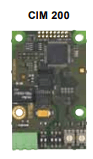
Grundfos E-pumps such as the CRE, TPE, NBE and NKE and the MAGNA3 circulator are speed-controlled pumps for irrigation, circulation and heating water, also in greenhouses, and connect to Modbus through a CIM 200 or CIM 500 module. This Modbus RTU template reads head, flow, power, energy, temperatures and alarm codes and lets you write start and stop, control mode and setpoint from ModbusCloud.
- Protocol
- Modbus RTU
- Connection
- RS485, 19200 baud
- Registers
- 161, read and write
- Brand
- Grundfos
- Key readings
- Head · Volume flow · Power consumption · Energy consumption · Motor speed · Pumped liquid temperature · Alarm and warning code · Operating hours
- Available commands
- Start and stop · Control mode · Setpoint · Operating mode · Maximum flow limit · Relay outputs
- Compatible models
- CRE · CRNE · CRIE · MTRE · CHIE · CME · TPE · TPE Series 2000 · NBE · NKE · CUE · MAGNA3 · CIM 200 Modbus RTU · CIU 200 Modbus RTU · CIM 500 Modbus TCP · CIU 500 Modbus TCP · SoftCIM Modbus RTU (MGE with FM310/311/110)
- Last updated
Registers (161)
161 read, 73 write
| Name | Unit | Access | Address (Hidden until you enter your email) | Function (hidden) | Type (hidden) |
|---|---|---|---|---|---|
| Head | bar | Read | |||
| Volume Flow | m³/h | Read | |||
| Power | W | Read | |||
| Speed | rpm | Read | |||
| Frequency | Hz | Read | |||
| Relative Performance | % | Read | |||
| Motor Current | A | Read | |||
| Pumped Liquid Temperature | K | Read | |||
| Differential Pressure | bar | Read | |||
| Actual Setpoint | % | Read | |||
| User Setpoint | % | Read | |||
| Specific Energy Consumption | Read | ||||
| DC Link Voltage | V | Read | |||
| Motor Voltage | V | Read | |||
| Load Percent | % | Read | |||
| Torque | Nm | Read | |||
| Remote Flow | m³/h | Read | |||
| Inlet Pressure | bar | Read | |||
| Outlet Pressure | bar | Read | |||
| Remote Pressure 1 | bar | Read | |||
| Remote Pressure 2 | bar | Read | |||
| Inlet Differential Pressure | bar | Read | |||
| Outlet Differential Pressure | bar | Read | |||
| Remote Differential Pressure | bar | Read | |||
| Feed Tank Level | m | Read | |||
| Storage Tank Level | m | Read | |||
| Remote Temperature 1 | K | Read | |||
| Remote Temperature 2 | K | Read | |||
| Remote Differential Temperature | K | Read | |||
| Ambient Temperature | K | Read | |||
| Aux Sensor Input | % | Read | |||
| Conductivity | µS/cm | Read | |||
| pH | pH | Read | |||
| Turbidity | NTU | Read | |||
| Heat Power | W | Read | |||
| Heat Differential Temperature | K | Read | |||
| Power Electronics Temperature | K | Read | |||
| Electronics Temperature | K | Read | |||
| Motor Temperature | K | Read | |||
| Bearing Temperature DE | K | Read | |||
| Bearing Temperature NDE | K | Read | |||
| Digital Inputs | Read | ||||
| Digital Outputs | Read | ||||
| Pump Status Word | Read | ||||
| Alarm Code | Read | ||||
| Warning Code | Read | ||||
| Actual Control Mode | Read | ||||
| Actual Operation Mode | Read | ||||
| Process Feedback | % | Read | |||
| Control Source | Read | ||||
| Drive State | Read | ||||
| Flow Estimation State | Read | ||||
| Bearing Service | Read | ||||
| Feedback Sensor Unit | Read | ||||
| Feedback Sensor Min | Read | ||||
| Feedback Sensor Max | Read | ||||
| Nominal Frequency | Hz | Read | |||
| Min Frequency | % | Read | |||
| Max Frequency | % | Read | |||
| Setpoint Range Min | % | Read | |||
| Setpoint Range Max | % | Read | |||
| Actual Kp | Read | ||||
| Actual Ti | s | Read | |||
| Actual Direct Control | Read | ||||
| Max Flow Limit | m³/h | Read | |||
| Control Register | Read and write | ||||
| Control Mode Request | Read and write | ||||
| Operation Mode Request | Read and write | ||||
| Setpoint | % | Read and write | |||
| Max Flow Limit Setting | m³/h | Read and write | |||
| Relay Control | Read and write | ||||
| Sensor Feedback | % | Read and write | |||
| Kp Setting | Read and write | ||||
| Ti Setting | s | Read and write | |||
| Direct Control Setting | Read and write | ||||
| Set Pump Clock | Read and write | ||||
| Watchdog | s | Read and write | |||
| Auto Ack Control Bits | Read and write | ||||
| Slave Minimum Reply Delay | ms | Read and write | |||
| Register Offset | Read and write | ||||
| Software Defined Modbus Address | Read and write | ||||
| Software Defined Bit Rate | Read and write | ||||
| Software Defined Parity | Read and write | ||||
| Software Defined Stop Bits | Read and write | ||||
| GENIbus LED Off | Read and write | ||||
| Energy | kWh | Read | |||
| Operating Time | h | Read | |||
| Powered Time | h | Read | |||
| Number of Starts | Read | ||||
| Volume Direction 1 | m³ | Read | |||
| Volume Direction 2 | m³ | Read | |||
| Heat Energy Direction 1 | kWh | Read | |||
| Heat Energy Direction 2 | kWh | Read | |||
| Pump Clock | Read | ||||
| GENIbus CRC Error Count | Read | ||||
| GENIbus Data Error Count | Read | ||||
| GENIbus TX Count | Read | ||||
| GENIbus RX Count | Read | ||||
| Actual Modbus Address | Read | ||||
| CIM Version Number | Read | ||||
| Unit Family | Read | ||||
| Unit Type | Read | ||||
| Unit Version | Read | ||||
| Product Software Version HI | Read | ||||
| Product Software Version LO | Read | ||||
| Product Software Day Month | Read | ||||
| Product Software Year | Read | ||||
| Simulation Alarm Code | Read and write | ||||
| Simulation Warning Code | Read and write | ||||
| Simulation Activate | Read and write | ||||
| Simulation Active | Read | ||||
| User Register 1 | Read and write | ||||
| User Register 2 | Read and write | ||||
| User Register 3 | Read and write | ||||
| User Register 4 | Read and write | ||||
| User Register 5 | Read and write | ||||
| User Register 6 | Read and write | ||||
| User Register 7 | Read and write | ||||
| User Register 8 | Read and write | ||||
| User Register 9 | Read and write | ||||
| User Register 10 | Read and write | ||||
| User Register 11 | Read and write | ||||
| User Register 12 | Read and write | ||||
| User Register 13 | Read and write | ||||
| User Register 14 | Read and write | ||||
| User Register 15 | Read and write | ||||
| User Register 16 | Read and write | ||||
| User Register 17 | Read and write | ||||
| User Register 18 | Read and write | ||||
| User Register 19 | Read and write | ||||
| User Register 20 | Read and write | ||||
| User Register 21 | Read and write | ||||
| User Register 22 | Read and write | ||||
| User Register 23 | Read and write | ||||
| User Register 24 | Read and write | ||||
| User Register 25 | Read and write | ||||
| User Register 26 | Read and write | ||||
| User Register 27 | Read and write | ||||
| User Register 28 | Read and write | ||||
| User Register 29 | Read and write | ||||
| User Register 30 | Read and write | ||||
| User Register 31 | Read and write | ||||
| User Register 32 | Read and write | ||||
| User Register 33 | Read and write | ||||
| User Register 34 | Read and write | ||||
| User Register 35 | Read and write | ||||
| User Register 36 | Read and write | ||||
| User Register 37 | Read and write | ||||
| User Register 38 | Read and write | ||||
| User Register 39 | Read and write | ||||
| User Register 40 | Read and write | ||||
| User Register 41 | Read and write | ||||
| User Register 42 | Read and write | ||||
| User Register 43 | Read and write | ||||
| User Register 44 | Read and write | ||||
| User Register 45 | Read and write | ||||
| User Register 46 | Read and write | ||||
| User Register 47 | Read and write | ||||
| User Register 48 | Read and write | ||||
| User Register 49 | Read and write | ||||
| User Register 50 | Read and write |
Loading registers…
Send your device list
If a device is not in the library yet, we build the template for free as soon as we have the register data.
Use cases
- Show head, flow and power of all irrigation pumps on one dashboard and compare them per pump.
- Send an email or webhook alert when the pump reports an alarm code, for example dry running or a blocked pump.
- Track energy consumption and operating hours per pump in the history to plan maintenance.
- Change the setpoint or control mode of a circulation pump from the portal, or lower it at night with a scheduled automation.
- Follow the pumped liquid temperature and heat power of a heating circuit pump over 365 days of history.
- Get an alert when the flow drops below a threshold while the pump runs, for example after a blocked filter.
Installation
Fit the CIM 200 module in the pump, or a CIU 200 box for a CUE drive, and set the Modbus address on the rotary switches SW6 and SW7.
Leave the DIP switches at 19200 baud, even parity and 1 stop bit, or set the speed and parity that your bus uses.
Connect D1 (positive) and D0 (negative) to the RS485 lines of the ModbusCloud Gateway with screened twisted pair. Switch on the termination only at both ends of the bus.
In ModbusCloud, add a Modbus device with the same address, 19200 baud, 8 data bits, even parity and 1 stop bit, and import this template.
Check that Speed and Unit Family show plausible values. If nothing answers, swap the two data wires.
Things to watch for
The pump does not answer on RS485. What should I check?
Check that address, baud rate and parity in ModbusCloud match the CIM 200. The default is 19200 baud, even parity and 1 stop bit, and the address comes from the rotary switches SW6 and SW7. A flashing red LED1 points to a speed, parity or wiring fault, so check the switches and swap D1 and D0 if needed. Switch on the termination only at the two ends of the bus.
Why do some registers show 65535?
65535 means the pump does not have that value. Many readings need a sensor on an analog input, such as inlet pressure, tank level or the external temperatures, and some only exist on newer MGE motors or on the MAGNA3. Set up the sensor on the pump, then restart the module so it picks up the sensor scaling.
Why does the liquid temperature read around 290?
The pump reports all temperatures in kelvin with two decimals. Subtract 273.15 for degrees Celsius, so 293.15 K is 20 °C. Inlet pressure and the tank levels carry a fixed offset too: subtract 1 bar from the inlet pressure and 100 m from the tank levels.
The pump ignores the setpoint I write. Why?
The pump only follows Modbus in remote mode. Write 3 to the Control Register for remote and start, or 1 for remote and stop, and check bit 8 of the Pump Status Word. Writing registers is off by default per gateway, so request it in the portal first. If you enable the watchdog, make its timeout longer than the polling interval, otherwise the pump falls back to local mode.
Does this also work with the CIM 500 over Ethernet?
Yes, the CIM 500 has the same registers over Modbus TCP. Set its protocol rotary switch to 1, give the Modbus TCP interface an IP address in the web server of the module (default 192.168.1.100) and connect it to the network of the ModbusCloud Gateway. Port 502 is always active and the unit ID is ignored.
Want to see how it works?
