








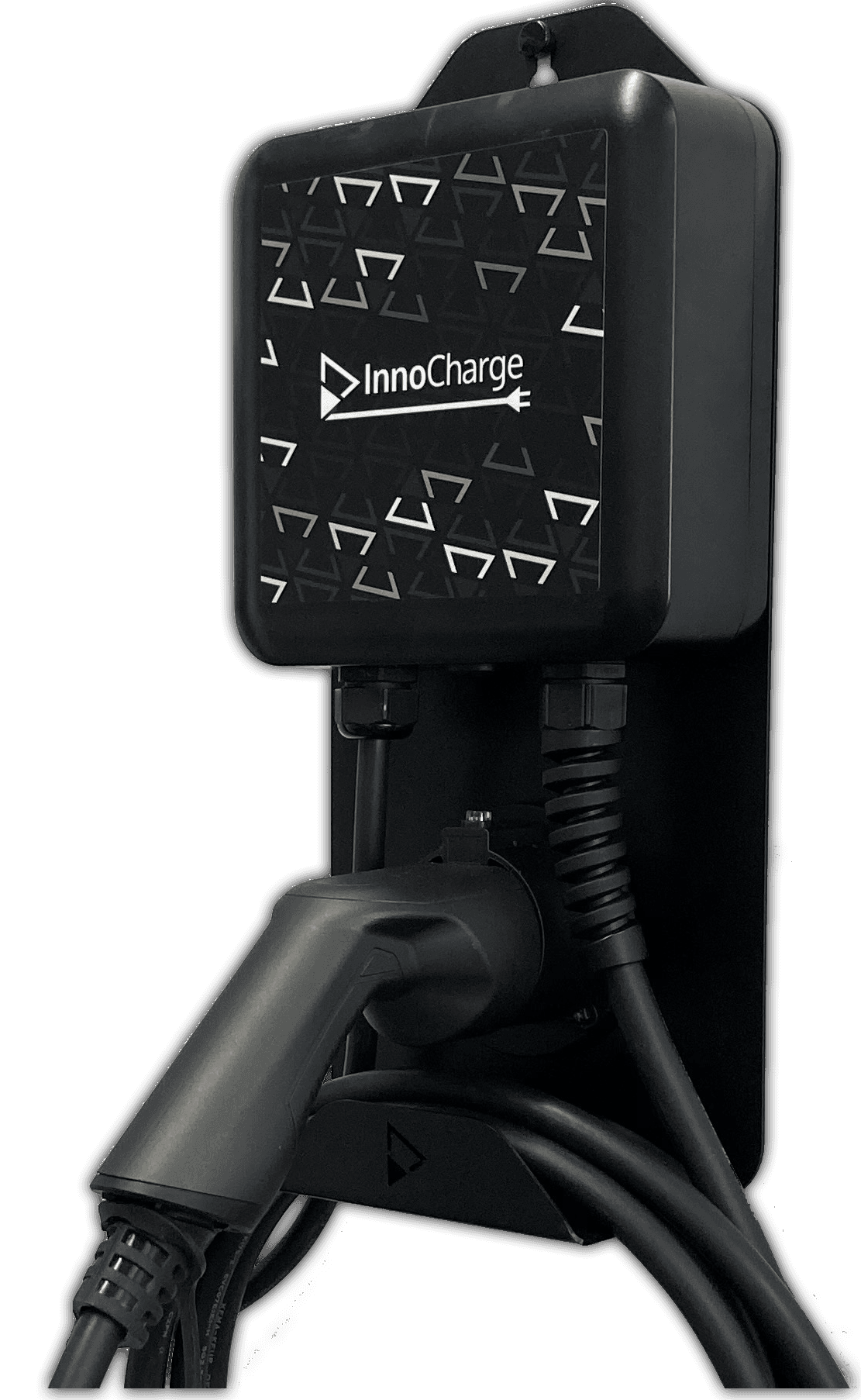
01 InnoCharge Wallbox
Controls and monitors InnoCharge EV wallbox charging via Modbus RTU.
This template provides a Modbus RTU communication interface for InnoTune InnoCharge wallboxes. It reads EVSE status, installed amps, and throttled amps, and allows control of charge current throttling, station disable, force unlock, and reboot.
- Protocol
- Modbus RTU
- Connection
- RS485, 9600 baud
- Registers
- 9, read and write
- Brand
- InnoTune
- Key readings
- EVSE status · Actual Modbus ID · Installed amps · Throttled amps · Disable charging station status
- Available commands
- Disable charging station · Throttled amps · Force unlock · Reboot unit
- Compatible models
- InnoCharge Wallbox
- Last updated
Registers (9)
9 read, 6 write
| Name | Unit | Access | Address (Hidden until you enter your email) | Function (hidden) | Type (hidden) |
|---|---|---|---|---|---|
| 0=EVSE status 1 Ready, 2 Connected, 3 Charging | Read | ||||
| 1=Actual Modbus ID, default 1 | Read | ||||
| 2=Installed Amps (Read from rotary switch) | A | Read | |||
| 3=Force unlock (Always 0) | Read and write | ||||
| 4=Disable Charging-Station | Read and write | ||||
| 5=Trottled A | A | Read and write | |||
| 6=New Modbus ID | Read and write | ||||
| 7=Write new ID to EPROM | Read and write | ||||
| 8=Reboot Unit | Read and write |
Loading registers…
Send your device list
If a device is not in the library yet, we build the template for free as soon as we have the register data.
Use cases
- Monitor EVSE status and charge current in real time on a cloud dashboard for each customer site.
- Throttle the charge current remotely to implement basic load management across multiple wallboxes.
- Create an alert when the EVSE status indicates a fault or the charging station has been unexpectedly disabled.
- Reboot or force unlock an InnoCharge wallbox remotely without dispatching a technician to the site.
- Log historical charging data to analyze usage patterns and energy consumption per charging station.
Installation
Connect the ModbusCloud Gateway to the InnoCharge wallbox RS-485 terminals using a twisted pair cable for the A and B data lines.
Configure the gateway serial port to 9600 baud, 8 data bits, 1 stop bit, and verify the parity setting matches the wallbox (factory default is none, but confirm on the device).
Set the Modbus slave address on the wallbox to a unique value if multiple units share the same bus, and write the address to EPROM register 7 to persist it.
Import the InnoTune InnoCharge Wallbox template from the ModbusCloud template library into your project.
Assign the correct slave address in the template configuration to match the address set on the wallbox.
Verify communication by checking that EVSE status and installed amps values appear on the ModbusCloud dashboard.
Things to watch for
Communication fails after wiring the gateway to the wallbox. What should I check?
Verify that the RS-485 A and B lines are not swapped. Confirm the baud rate is set to 9600 on both the gateway and the wallbox. Also check that the parity setting matches. The factory default is "none" but the template detected a value of 1, so confirm the actual device configuration.
I changed the Modbus slave address but it resets after a reboot. Why?
The new Modbus ID must be written to the EPROM register (register 7) to persist across power cycles. Writing to the standard address register alone will not survive a reboot.
Can I connect multiple InnoCharge wallboxes to a single gateway?
Yes, as long as each wallbox has a unique Modbus slave address on the RS-485 bus. Assign distinct addresses via EPROM register 7 on each unit and create a separate template instance per wallbox in ModbusCloud.
What register format does the InnoCharge wallbox use?
All registers are 16-bit integers starting at address 0. The protocol uses standard Modbus RTU framing with function codes 0x03 for reading and 0x10 for writing.






Want to see how it works?
