

Lovato DMG210
Modular three-phase multimeter for voltage, current, power, energy and power quality.
The Lovato DMG210 is a modular three-phase multimeter that measures voltage, current, power, energy and power quality in low-voltage distribution boards. This Modbus RTU template reads all measurements, peak and demand values and energy counters, and lets you reset values, start the wiring test and change setup parameters from ModbusCloud.
- Protocol
- Modbus RTU
- Connection
- RS485, 9600 baud
- Registers
- 240, read and write
- Brand
- Lovato
- Key readings
- Voltage per phase · Current per phase · Active power · Reactive and apparent power · Power factor · THD of voltage and current · Energy counters · Peak and demand values
- Available commands
- Reset of peak values · Reset of partial counters · Wiring test · Setup parameters
- Compatible models
- DMG210
- Last updated
Registers (240)
238 read, 6 write
| Name | Unit | Access | Address (Hidden until you enter your email) | Function (hidden) | Type (hidden) |
|---|---|---|---|---|---|
| Voltage L1-N | V | Read | 1 | FC04 | uint32 |
| Voltage L2-N | V | Read | 3 | FC04 | uint32 |
| Voltage L3-N | V | Read | 5 | FC04 | uint32 |
| Current L1 | A | Read | 7 | FC04 | uint32 |
| Current L2 | A | Read | 9 | FC04 | uint32 |
| Current L3 | A | Read | |||
| Voltage L1-L2 | V | Read | |||
| Voltage L2-L3 | V | Read | |||
| Voltage L3-L1 | V | Read | |||
| Active Power L1 | W | Read | |||
| Active Power L2 | W | Read | |||
| Active Power L3 | W | Read | |||
| Reactive Power L1 | var | Read | |||
| Reactive Power L2 | var | Read | |||
| Reactive Power L3 | var | Read | |||
| Apparent Power L1 | VA | Read | |||
| Apparent Power L2 | VA | Read | |||
| Apparent Power L3 | VA | Read | |||
| Power Factor L1 | Read | ||||
| Power Factor L2 | Read | ||||
| Power Factor L3 | Read | ||||
| Frequency | Hz | Read | |||
| Equivalent Phase Voltage | V | Read | |||
| Equivalent Line Voltage | V | Read | |||
| Equivalent Current | A | Read | |||
| System Active Power | W | Read | |||
| System Reactive Power | var | Read | |||
| System Apparent Power | VA | Read | |||
| System Power Factor | Read | ||||
| Line Voltage Asymmetry | % | Read | |||
| Phase Voltage Asymmetry | % | Read | |||
| Current Asymmetry | % | Read | |||
| Neutral Current | A | Read | |||
| THD Voltage L1 | % | Read | |||
| THD Voltage L2 | % | Read | |||
| THD Voltage L3 | % | Read | |||
| THD Current L1 | % | Read | |||
| THD Current L2 | % | Read | |||
| THD Current L3 | % | Read | |||
| THD Voltage L1-L2 | % | Read | |||
| THD Voltage L2-L3 | % | Read | |||
| THD Voltage L3-L1 | % | Read | |||
| Max Voltage L1-N | V | Read | |||
| Max Voltage L2-N | V | Read | |||
| Max Voltage L3-N | V | Read | |||
| Max Current L1 | A | Read | |||
| Max Current L2 | A | Read | |||
| Max Current L3 | A | Read | |||
| Max Voltage L1-L2 | V | Read | |||
| Max Voltage L2-L3 | V | Read | |||
| Max Voltage L3-L1 | V | Read | |||
| Max Active Power L1 | W | Read | |||
| Max Active Power L2 | W | Read | |||
| Max Active Power L3 | W | Read | |||
| Max Reactive Power L1 | var | Read | |||
| Max Reactive Power L2 | var | Read | |||
| Max Reactive Power L3 | var | Read | |||
| Max Apparent Power L1 | VA | Read | |||
| Max Apparent Power L2 | VA | Read | |||
| Max Apparent Power L3 | VA | Read | |||
| Max Power Factor L1 | Read | ||||
| Max Power Factor L2 | Read | ||||
| Max Power Factor L3 | Read | ||||
| Max Frequency | Hz | Read | |||
| Max Equivalent Phase Voltage | V | Read | |||
| Max Equivalent Line Voltage | V | Read | |||
| Max Equivalent Current | A | Read | |||
| Max System Active Power | W | Read | |||
| Max System Reactive Power | var | Read | |||
| Max System Apparent Power | VA | Read | |||
| Max System Power Factor | Read | ||||
| Max Line Voltage Asymmetry | % | Read | |||
| Max Phase Voltage Asymmetry | % | Read | |||
| Max Current Asymmetry | % | Read | |||
| Max Neutral Current | A | Read | |||
| Max THD Voltage L1 | % | Read | |||
| Max THD Voltage L2 | % | Read | |||
| Max THD Voltage L3 | % | Read | |||
| Max THD Current L1 | % | Read | |||
| Max THD Current L2 | % | Read | |||
| Max THD Current L3 | % | Read | |||
| Max THD Voltage L1-L2 | % | Read | |||
| Max THD Voltage L2-L3 | % | Read | |||
| Max THD Voltage L3-L1 | % | Read | |||
| Min Voltage L1-N | V | Read | |||
| Min Voltage L2-N | V | Read | |||
| Min Voltage L3-N | V | Read | |||
| Min Current L1 | A | Read | |||
| Min Current L2 | A | Read | |||
| Min Current L3 | A | Read | |||
| Min Voltage L1-L2 | V | Read | |||
| Min Voltage L2-L3 | V | Read | |||
| Min Voltage L3-L1 | V | Read | |||
| Min Active Power L1 | W | Read | |||
| Min Active Power L2 | W | Read | |||
| Min Active Power L3 | W | Read | |||
| Min Reactive Power L1 | var | Read | |||
| Min Reactive Power L2 | var | Read | |||
| Min Reactive Power L3 | var | Read | |||
| Min Apparent Power L1 | VA | Read | |||
| Min Apparent Power L2 | VA | Read | |||
| Min Apparent Power L3 | VA | Read | |||
| Min Power Factor L1 | Read | ||||
| Min Power Factor L2 | Read | ||||
| Min Power Factor L3 | Read | ||||
| Min Frequency | Hz | Read | |||
| Min Equivalent Phase Voltage | V | Read | |||
| Min Equivalent Line Voltage | V | Read | |||
| Min Equivalent Current | A | Read | |||
| Min System Active Power | W | Read | |||
| Min System Reactive Power | var | Read | |||
| Min System Apparent Power | VA | Read | |||
| Min System Power Factor | Read | ||||
| Min Line Voltage Asymmetry | % | Read | |||
| Min Phase Voltage Asymmetry | % | Read | |||
| Min Current Asymmetry | % | Read | |||
| Min Neutral Current | A | Read | |||
| Min THD Voltage L1 | % | Read | |||
| Min THD Voltage L2 | % | Read | |||
| Min THD Voltage L3 | % | Read | |||
| Min THD Current L1 | % | Read | |||
| Min THD Current L2 | % | Read | |||
| Min THD Current L3 | % | Read | |||
| Min THD Voltage L1-L2 | % | Read | |||
| Min THD Voltage L2-L3 | % | Read | |||
| Min THD Voltage L3-L1 | % | Read | |||
| Avg Voltage L1-N | V | Read | |||
| Avg Voltage L2-N | V | Read | |||
| Avg Voltage L3-N | V | Read | |||
| Avg Current L1 | A | Read | |||
| Avg Current L2 | A | Read | |||
| Avg Current L3 | A | Read | |||
| Avg Voltage L1-L2 | V | Read | |||
| Avg Voltage L2-L3 | V | Read | |||
| Avg Voltage L3-L1 | V | Read | |||
| Avg Active Power L1 | W | Read | |||
| Avg Active Power L2 | W | Read | |||
| Avg Active Power L3 | W | Read | |||
| Avg Reactive Power L1 | var | Read | |||
| Avg Reactive Power L2 | var | Read | |||
| Avg Reactive Power L3 | var | Read | |||
| Avg Apparent Power L1 | VA | Read | |||
| Avg Apparent Power L2 | VA | Read | |||
| Avg Apparent Power L3 | VA | Read | |||
| Avg Power Factor L1 | Read | ||||
| Avg Power Factor L2 | Read | ||||
| Avg Power Factor L3 | Read | ||||
| Avg Frequency | Hz | Read | |||
| Avg Equivalent Phase Voltage | V | Read | |||
| Avg Equivalent Line Voltage | V | Read | |||
| Avg Equivalent Current | A | Read | |||
| Avg System Active Power | W | Read | |||
| Avg System Reactive Power | var | Read | |||
| Avg System Apparent Power | VA | Read | |||
| Avg System Power Factor | Read | ||||
| Avg Line Voltage Asymmetry | % | Read | |||
| Avg Phase Voltage Asymmetry | % | Read | |||
| Avg Current Asymmetry | % | Read | |||
| Avg Neutral Current | A | Read | |||
| Avg THD Voltage L1 | % | Read | |||
| Avg THD Voltage L2 | % | Read | |||
| Avg THD Voltage L3 | % | Read | |||
| Avg THD Current L1 | % | Read | |||
| Avg THD Current L2 | % | Read | |||
| Avg THD Current L3 | % | Read | |||
| Avg THD Voltage L1-L2 | % | Read | |||
| Avg THD Voltage L2-L3 | % | Read | |||
| Avg THD Voltage L3-L1 | % | Read | |||
| Max Demand Voltage L1-N | V | Read | |||
| Max Demand Voltage L2-N | V | Read | |||
| Max Demand Voltage L3-N | V | Read | |||
| Max Demand Current L1 | A | Read | |||
| Max Demand Current L2 | A | Read | |||
| Max Demand Current L3 | A | Read | |||
| Max Demand Voltage L1-L2 | V | Read | |||
| Max Demand Voltage L2-L3 | V | Read | |||
| Max Demand Voltage L3-L1 | V | Read | |||
| Max Demand Active Power L1 | W | Read | |||
| Max Demand Active Power L2 | W | Read | |||
| Max Demand Active Power L3 | W | Read | |||
| Max Demand Reactive Power L1 | var | Read | |||
| Max Demand Reactive Power L2 | var | Read | |||
| Max Demand Reactive Power L3 | var | Read | |||
| Max Demand Apparent Power L1 | VA | Read | |||
| Max Demand Apparent Power L2 | VA | Read | |||
| Max Demand Apparent Power L3 | VA | Read | |||
| Max Demand Power Factor L1 | Read | ||||
| Max Demand Power Factor L2 | Read | ||||
| Max Demand Power Factor L3 | Read | ||||
| Max Demand Frequency | Hz | Read | |||
| Max Demand Equivalent Phase Voltage | V | Read | |||
| Max Demand Equivalent Line Voltage | V | Read | |||
| Max Demand Equivalent Current | A | Read | |||
| Max Demand System Active Power | W | Read | |||
| Max Demand System Reactive Power | var | Read | |||
| Max Demand System Apparent Power | VA | Read | |||
| Max Demand System Power Factor | Read | ||||
| Max Demand Line Voltage Asymmetry | % | Read | |||
| Max Demand Phase Voltage Asymmetry | % | Read | |||
| Max Demand Current Asymmetry | % | Read | |||
| Max Demand Neutral Current | A | Read | |||
| Max Demand THD Voltage L1 | % | Read | |||
| Max Demand THD Voltage L2 | % | Read | |||
| Max Demand THD Voltage L3 | % | Read | |||
| Max Demand THD Current L1 | % | Read | |||
| Max Demand THD Current L2 | % | Read | |||
| Max Demand THD Current L3 | % | Read | |||
| Max Demand THD Voltage L1-L2 | % | Read | |||
| Max Demand THD Voltage L2-L3 | % | Read | |||
| Max Demand THD Voltage L3-L1 | % | Read | |||
| Phase Sequence | Read | ||||
| Total Imported Active Energy | kWh | Read | |||
| Total Exported Active Energy | kWh | Read | |||
| Total Imported Reactive Energy | kvarh | Read | |||
| Total Exported Reactive Energy | kvarh | Read | |||
| Total Apparent Energy | kVAh | Read | |||
| Partial Imported Active Energy | kWh | Read | |||
| Partial Exported Active Energy | kWh | Read | |||
| Partial Imported Reactive Energy | kvarh | Read | |||
| Partial Exported Reactive Energy | kvarh | Read | |||
| Partial Apparent Energy | kVAh | Read | |||
| Total Imported Active Energy 64-bit | kWh | Read | |||
| Total Exported Active Energy 64-bit | kWh | Read | |||
| Total Imported Reactive Energy 64-bit | kvarh | Read | |||
| Total Exported Reactive Energy 64-bit | kvarh | Read | |||
| Total Apparent Energy 64-bit | kVAh | Read | |||
| Partial Imported Active Energy 64-bit | kWh | Read | |||
| Partial Exported Active Energy 64-bit | kWh | Read | |||
| Partial Imported Reactive Energy 64-bit | kvarh | Read | |||
| Partial Exported Reactive Energy 64-bit | kvarh | Read | |||
| Partial Apparent Energy 64-bit | kVAh | Read | |||
| Total Hour Meter | s | Read | |||
| Partial Hour Meter | s | Read | |||
| Wiring Test Result | Read | ||||
| Command | Write | ||||
| System Reboot | Write | ||||
| Setup Menu Selection | Read and write | ||||
| Setup Submenu Selection | Read and write | ||||
| Setup Parameter Selection | Read and write | ||||
| Setup Parameter Value | Read and write |
Loading registers…
Send your device list
If a device is not in the library yet, we build the template for free as soon as we have the register data.
Use cases
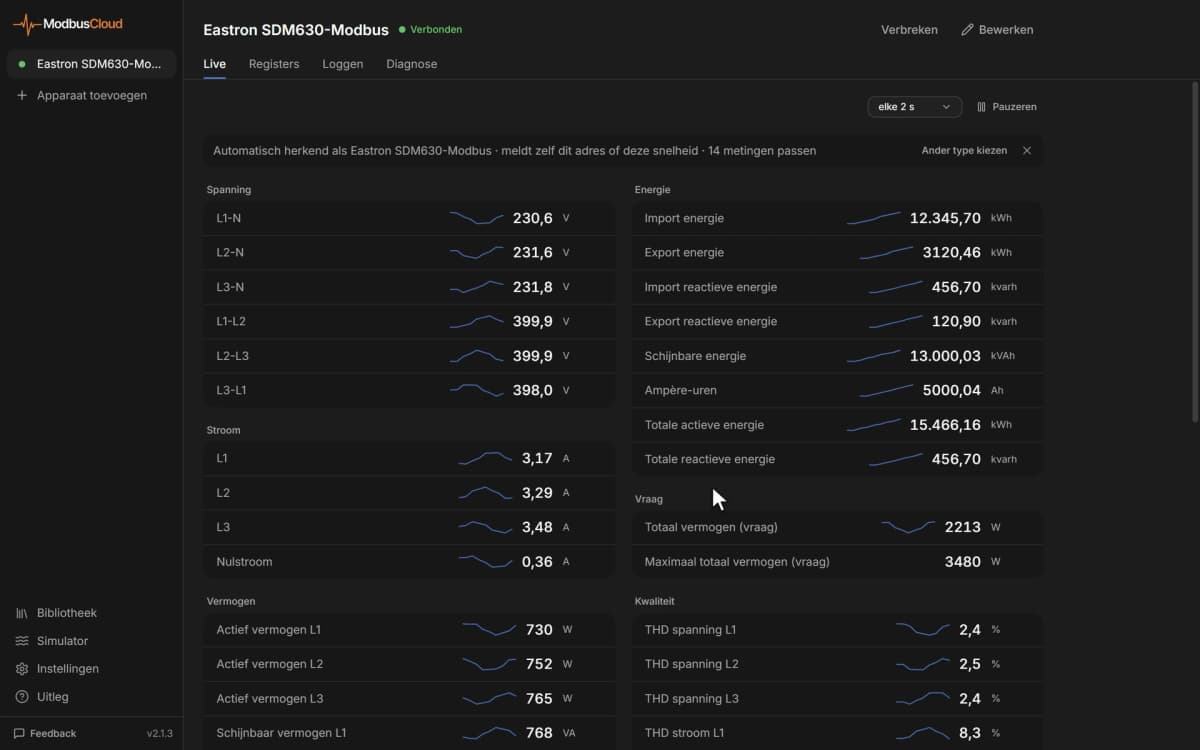
- Show voltage, current and total power of every feeder on one dashboard.
- Get an email alert when total active power goes above the capacity of a feeder or connection.
- Keep the energy counters in the history and report consumption per group or tenant each month.
- Compare current per phase and current asymmetry to balance the loads in a distribution board.
- Track THD of voltage and current to spot harmonics from drives or LED lighting.
- Reset the demand values and partial counters remotely at the start of a billing period.
Installation
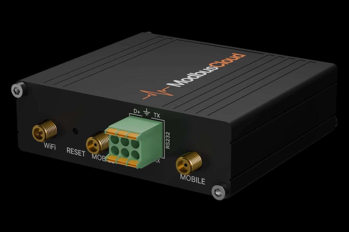
Connect A and B of the DMG210 to the RS485 port of the ModbusCloud Gateway, with termination at both ends of the bus.
On the meter, open menu M07 and set the address, speed (9600 by default), data format (8 bit, no parity) and protocol Modbus RTU.
In ModbusCloud, add a Modbus device on the Gateway with the same address and import this template.
Check that voltage L1-N shows about 230 V and frequency about 50 Hz.
Things to watch for
The DMG210 does not answer on the RS485 bus. What should I check?
Check menu M07: the protocol must be Modbus RTU, and address, speed and data format must match the device in ModbusCloud, by default address 1, 9600 baud, 8 bit, no parity, 1 stop bit. Swap A and B if nothing comes back and terminate both ends of the bus.
Frequency reads 500 Hz or 5 Hz instead of 50 Hz.
The template reads the frequency with the resolution Lovato gives for the DMG210. If your meter is off by a factor of ten, compare with the display and adjust the scale of the frequency registers.
The 64-bit energy counters give an error. Why?
The 64-bit counters need DMG210 software revision 07 or later. On older firmware use the 32-bit energy counters, which are also in the template.
Several meters on one bus answer at random.
Every DMG210 leaves the factory with address 1. Give each meter its own address in menu M07 before you connect them on one line, and use the same speed and data format on all of them.
How do I change a setup parameter such as the CT primary?
Write the menu, submenu and parameter number to the setup selection registers, then write the new value to the setup value register. Write 1 to the reboot register to save; the meter restarts without a Modbus answer. Read the value back afterwards.
More Lovato templates


Want to see how it works?