








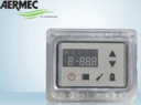
AERMEC Moducontrol
Integrates and supervises AERMEC chillers and heat pumps via Moducontrol controller.
This template integrates AERMEC chillers and heat pumps equipped with the Moducontrol controller via Modbus RTU. It reads temperatures, machine status, alarms, and power output, and provides remote on/off control and alarm reset.
- Protocol
- Modbus RTU
- Connection
- RS485, 9600 baud
- Registers
- 23, read and write
- Brand
- Aermec
- Key readings
- TIA / TUA temperatures · TGP temperature · Set Point · Machine Status · Cumulative Alarms / Pre-alarms · Power Supplied (%)
- Available commands
- ON-Off · RESET Alarm
- Compatible models
- ANL050
- Last updated
Registers (23)
22 read, 2 write
| Name | Unit | Access | Address (Hidden until you enter your email) | Function (hidden) | Type (hidden) |
|---|---|---|---|---|---|
| ON-Off | Read and write | ||||
| TIA | °C | Read | |||
| CP | Read | ||||
| Cumulative Alarms | Read | ||||
| Cumulative Pre-alarms | Read | ||||
| TUA | °C | Read | |||
| TGP | °C | Read | |||
| Set Point | °C | Read | |||
| Machine Status | Read | ||||
| Alarm 1 MT Compressor | Read | ||||
| Alarm 2 MT Fan | Read | ||||
| Alarm 3 high pression | Read | ||||
| Alarm 4 water | Read | ||||
| Alarm 5 low pression | Read | ||||
| Alarm 6 NTC1 | Read | ||||
| Alarm 7 NTC2 | Read | ||||
| Alarm 8 Antifreeze | Read | ||||
| Alarm 9 NTC4 | Read | ||||
| Alarm 10 Pressure Gas Temp | Read | ||||
| Alarm 16 Low Yield | Read | ||||
| Alarm 17 MT Pup | Read | ||||
| Po Power supplied | % | Read | |||
| RESET Allarm | Write |
Loading registers…
Send your device list
If a device is not in the library yet, we build the template for free as soon as we have the register data.
Use cases
- Monitor TIA, TUA, and TGP temperatures on a live dashboard to verify chiller performance remotely.
- Create an alert when cumulative alarms or pre-alarms are triggered so you can respond before downtime occurs.
- Log power supplied percentage over time to identify efficiency degradation or unusual load patterns.
- Remotely switch the AERMEC unit on or off from the ModbusCloud platform during commissioning or seasonal shutdowns.
- Reset alarms remotely after resolving a fault, avoiding an unnecessary site visit.
- Track set point values across multiple AERMEC units on different sites from a single dashboard.
Installation
Connect the Modbus RTU wiring (A, B, and GND) from the AERMEC Moducontrol controller's RS-485 port to the ModbusCloud Gateway.
Set the Modbus slave address on the Moducontrol controller to match the address configured in the ModbusCloud template.
Verify that the baud rate on the Moducontrol controller is set to 9600, matching the template default.
Import the AERMEC Moducontrol template in the ModbusCloud platform and assign it to the correct gateway and slave address.
Add a 120 ohm termination resistor at the end of the RS-485 bus if the AERMEC unit is the last device on the line.
Power cycle the gateway and confirm that live readings such as TIA temperature and machine status appear in the dashboard.
Things to watch for
The template shows identical values for CP and TGP. Is this normal?
Yes. Registers CP and TGP share the same Modbus address (address 5). The value returned depends on the operating context of the Moducontrol controller. Check the AERMEC documentation for your specific model to confirm which parameter is active.
Can I use this template with AERMEC models other than the ANL050?
Yes. The template works with any AERMEC chiller or heat pump equipped with the Moducontrol controller. The register map is consistent across models, though you should verify key registers during commissioning.
Communication fails or returns no data after wiring the gateway. What should I check?
Confirm that the RS-485 wiring polarity (A and B) is correct and that the baud rate is set to 9600 on both the Moducontrol controller and the gateway. Also verify the Modbus slave address matches the template configuration.
Is Modbus enabled by default on the Moducontrol controller?
On some AERMEC models, Modbus communication must be explicitly enabled in the controller settings. Consult the Moducontrol installation manual for your unit and ensure the serial communication option is activated.






Want to see how it works?
