









Schneider Electric Altivar ATV212
HVAC variable speed drive for fans and pumps: speed, current, power, faults and run commands over Modbus RTU.
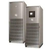
The Schneider Electric Altivar ATV212 is a variable speed drive that controls fans and pumps in heating, ventilation and air conditioning systems. This Modbus RTU template reads frequency, speed, current, power, energy, run hours and trip codes, and lets you start, stop and set the speed of the drive from ModbusCloud.
- Protocol
- Modbus RTU
- Connection
- RS485, 19200 baud
- Registers
- 81, read and write
- Brand
- Schneider Electric
- Key readings
- Output frequency · Output speed · Output current · Input power · Energy · Run hours · Trip code · Status word
- Available commands
- Command word · Frequency setpoint · Speed setpoint · Relay outputs · Analog output · Communication timeout
- Compatible models
- ATV212H (IP21, 0.75 to 75 kW) · ATV212W (IP55, 0.75 to 75 kW) · Schneider Electric Altivar 212 variable speed drives
- Last updated
Registers (81)
79 read, 31 write
| Name | Unit | Access | Address (Hidden until you enter your email) | Function (hidden) | Type (hidden) |
|---|---|---|---|---|---|
| Output Frequency | Hz | Read | |||
| Output Speed | rpm | Read | |||
| Output Current | % | Read | |||
| Torque | % | Read | |||
| DC Bus Voltage | % | Read | |||
| Input Power | kW | Read | |||
| Output Power | kW | Read | |||
| Input Energy | Wh | Read | |||
| Output Energy | Wh | Read | |||
| Motor Load | % | Read | |||
| Drive Load | % | Read | |||
| Cumulative Run Time | h | Read | |||
| Cumulative Power On Time | h | Read | |||
| Status Word | Read | ||||
| Status Word 2 | Read | ||||
| Status Word 3 | Read | ||||
| Trip Code | Read | ||||
| Alarm Code | Read | ||||
| Run Time Alarm | Read | ||||
| Latest Trip Code | Read | ||||
| 2nd Previous Trip Code | Read | ||||
| 3rd Previous Trip Code | Read | ||||
| 4th Previous Trip Code | Read | ||||
| Command Mode Status | Read | ||||
| Setpoint Mode Status | Read | ||||
| Digital Inputs Status | Read | ||||
| Digital Outputs Status | Read | ||||
| Analog Input VIA | Read | ||||
| Analog Input VIB | Read | ||||
| Output Frequency At Last Trip | Hz | Read | |||
| Frequency Reference Before Ramp | Hz | Read | |||
| Frequency Reference After Ramp | Hz | Read | |||
| Estimated Speed | Hz | Read | |||
| PID Feedback Value | Hz | Read | |||
| Torque Current | % | Read | |||
| Exciting Current | % | Read | |||
| Output Voltage | % | Read | |||
| Status Word At Last Trip | Read | ||||
| Status Word 2 At Last Trip | Read | ||||
| Status Word 3 At Last Trip | Read | ||||
| Digital Inputs At Last Trip | Read | ||||
| Digital Outputs At Last Trip | Read | ||||
| Command Word | Read and write | ||||
| Command Word 2 | Read and write | ||||
| Frequency Setpoint | Hz | Read and write | |||
| Speed Setpoint | rpm | Read and write | |||
| Relay Output Command | Read and write | ||||
| Analog Output Command | Read and write | ||||
| Damper Feedback | Read and write | ||||
| Command Mode | Read and write | ||||
| Frequency Mode | Read and write | ||||
| Auto Ramp | Read and write | ||||
| Acceleration Time 1 | Read and write | ||||
| LI R Function | Read and write | ||||
| Remote Speed Reference 2 | Read and write | ||||
| RJ45 Baud Rate | Read and write | ||||
| RJ45 Parity | Read and write | ||||
| Modbus Address | Read and write | ||||
| Communication Timeout | s | Read and write | |||
| Communication Channel | Read and write | ||||
| Network Baud Rate | Read and write | ||||
| Network Parity | Read and write | ||||
| Network Protocol | Read and write | ||||
| Communication Fault Setting | Read and write | ||||
| Block Write Data 1 | Read and write | ||||
| Block Write Data 2 | Read and write | ||||
| Block Read Data 1 | Read and write | ||||
| Block Read Data 2 | Read and write | ||||
| Block Read Data 3 | Read and write | ||||
| Block Read Data 4 | Read and write | ||||
| Block Read Data 5 | Read and write | ||||
| Indirect Read Value 1 | Read | ||||
| Indirect Read Value 2 | Read | ||||
| Indirect Read Value 3 | Read | ||||
| Indirect Read Value 4 | Read | ||||
| Indirect Read Value 5 | Read | ||||
| Indirect Write Word 1 | Write | ||||
| Indirect Write Word 2 | Write | ||||
| Drive Model Code | Read | ||||
| Drive Model Code F805 | Read | ||||
| Drive Class | Read |
Loading registers…
Send your device list
If a device is not in the library yet, we build the template for free as soon as we have the register data.
Use cases
- Show speed, current and power of every fan and pump drive in a building on one dashboard.
- Send an alert when the trip code is not 0 so you know which fault stopped the drive.
- Track energy and run hours per drive in the 365-day history to plan maintenance.
- Start, stop or change the speed of a fan from an automation on a schedule.
- Compare motor load and drive load across drives to spot a pump that works too hard.
Installation
Connect RS485 A and B of the open style terminals or the RJ45 port to the RS485 port of the ModbusCloud Gateway, with termination at both bus ends.
On the drive, set the Modbus address (F802), 19200 baud and even parity (F820 and F821 for the terminals, F800 and F801 for RJ45) and power cycle.
To control the drive from Modbus, set CMOd to 2 and FMOd to 4.
In ModbusCloud, add a Modbus RTU device with the same address, 19200 baud, 8 data bits, even parity, and import this template.
Check that output frequency and status word show plausible values.
Things to watch for
The drive does not answer on the bus.
Check that F807 points to the port you wired: 0 is RJ45, 1 is the open style terminals. Baud rate and parity changes only take effect after a power cycle. Swap A and B if nothing answers, and make sure every device on the bus has its own address.
Some values read fine but a block read fails.
The Altivar 212 answers reads of one register at a time. Only the indirect block at the configured read block addresses returns up to five words in one request. Read each value as a single register.
The drive ignores the frequency setpoint or run command.
The drive only takes commands and setpoint from Modbus when CMOd is 2 and FMOd is 4, or when bit 15 and bit 14 of the command word are set. Writing 50176 runs the drive forward with Modbus priority. Without valid requests within the communication timeout, the drive trips on Err5 or Err8.
What should I check before writing to the drive?
A written command word starts or stops the motor right away, and a reset clears a trip. Agree on who controls the drive, keep the communication timeout active, and note that writing registers from ModbusCloud is switched on per gateway on request.
More Schneider Electric templates

Want to see how it works?
