

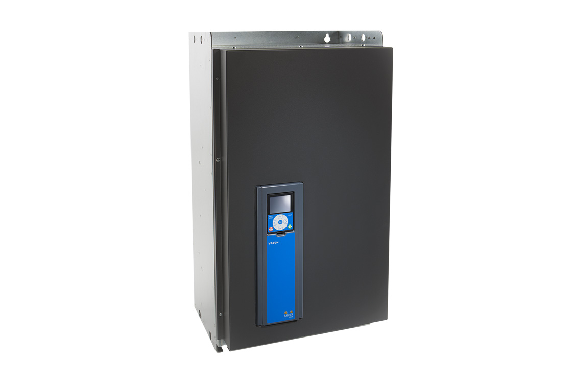
Vacon 100
Vacon
Frequency converter: frequency, speed, current, torque, power, DC link voltage and fault code over Modbus RTU (RS485).
Overview
Key readings
- Output frequency and motor speed
- Motor current (0.1 A)
- Motor torque and motor power in percent
- Motor voltage and DC link voltage
- Active fault code
- Status word: ready, running, fault, alarm
- Operation time counter
Use cases
- Get an alert when Active Fault Code is not equal to 0, so you know which fault stopped the pump before you drive out.
- Log Motor Power and Output Frequency to see how hard a fan or pump works over the day and whether the speed reference makes sense.
- Watch DC Link Voltage to spot supply dips or overvoltage during braking that keep tripping the drive.
- Check bit 4 of Status Word to catch alarms that do not stop the drive yet, such as a warning before a fault.
- Track Operation Time Days and Hours to plan service intervals for the drive and the motor.
Installation
- 1Connect the RS485 terminals A and B of the Vacon 100 control board to the RS485 port of your ModbusCloud Gateway and terminate the bus at both ends.
- 2On the drive open the Modbus RTU parameters (P5.8.3.1 in the newer manual), check slave address 1, 9600 baud, parity Even and stop bits, and set the communication time-out to 0 so slow polling does not raise a communication error.
- 3In ModbusCloud, add a Modbus device (RTU) with address 1, 9600 baud, 8 data bits, even parity and 2 stop bits, then import this template.
- 4Check the link: DC Link Voltage should show a plausible value as soon as the drive has mains voltage, and Status Word bit 0 should be 1 when the drive is ready.
Things to watch for
- The drive raises a fieldbus communication fault after a while.
- The Modbus RTU communication time-out (ID 2321) is 10 seconds by default. A master that polls every minute or less often leaves longer gaps, so the drive reports a communication error. Set the time-out to 0, which the manual describes as no fault generated, or poll faster with the master that controls the drive.
- The drive does not answer at all. What should I check?
- Compare address, baud rate, parity and stop bits with the drive: defaults are address 1, 9600 baud, parity Even and the stop bits parameter on 2. Many tools default to no parity. Swap A and B if nothing answers, and check that only one master is on the line. The Modbus diagnostic counters on the drive show CRC and parity errors.
- Why is my motor current 10 times off compared with the display?
- Application ID 3 Motor Current has a scale that depends on the drive size. The template reads ID 45 Motor Current 1 Decimal instead, which is always in 0.1 A. If you add ID 3 yourself, check the number of decimals on the drive display for that size.
- Process data out shows other values than the manual says.
- Registers 2104 to 2111 carry whatever IDs are mapped to process data out 1 to 8, and the application or a user may have changed the defaults. That is why the template reads the measurements directly by application ID at registers 1, 2, 4, 5, 6, 7, 37 and 45, which do not move.
Registers (13)
13 read / 0 write
| Name | Address | Function | Type | Unit | Access |
|---|---|---|---|---|---|
Output Frequency Output frequency of the drive in 0.01 Hz. Application ID 1, read directly at register 1 (default content of Process Data Out 1). | ••• | ••• | ••• | Hz | R |
Motor Speed Motor speed in rpm. Application ID 2, register 2 (default content of Process Data Out 2). | ••• | ••• | ••• | rpm | R |
Motor Current Motor current with 1 decimal, 0.1 A. Application ID 45 Motor Current 1 Decimal, register 45. ID 3 is left out because its scale depends on the drive size. | ••• | ••• | ••• | A | R |
Motor Torque Motor torque in percent of the nominal motor torque, 0.1 %. Application ID 4, register 4 (default content of Process Data Out 4). | ••• | ••• | ••• | % | R |
Motor Power Motor power in percent of the nominal motor power, 0.1 %. Application ID 5, register 5 (default content of Process Data Out 5). | ••• | ••• | ••• | % | R |
Motor Voltage Motor voltage in 0.1 V. Application ID 6, register 6 (default content of Process Data Out 6). | ••• | ••• | ••• | V | R |
DC Link Voltage DC link voltage in V. Application ID 7, register 7 (default content of Process Data Out 7). | ••• | ••• | ••• | V | R |
Active Fault Code Code of the active fault, 0 when no fault is active. Look the code up in the fault list of the application manual. Application ID 37, register 37 (default content of Process Data Out 8). | ••• | ••• | ••• | R | |
Status Word FB status word, bit coded: bit 0 ready, bit 1 running, bit 2 counterclockwise, bit 3 fault active, bit 4 alarm active, bit 5 at reference, bit 6 zero speed, bit 7 motor magnetized. | ••• | ••• | ••• | R | |
Actual Speed Percent FB actual speed, 0 to 100.00 % of the speed range (unit 0.01 %). Register 2103. | ••• | ••• | ••• | % | R |
Operation Time Years Operation day counter, years part. Read together with the days and hours registers. Register 40001. | ••• | ••• | ••• | R | |
Operation Time Days Operation day counter, days part. Register 40002. | ••• | ••• | ••• | d | R |
Operation Time Hours Operation day counter, hours part. Register 40003. | ••• | ••• | ••• | h | R |
Loading registers…
Read the Vacon 100 remotely
We load the templates onto the gateway and set up your portal, you connect it at your customer's site. Tell us briefly what you need and we'll send a proposal.
From €295 + €149/year.
Prefer to configure it yourself? Order the gateway in the shop·Or see the live demo first
More RTU templates

Alnor HRU
Alnor Systemy Wentylacji Sp. z o. o.
Controls and monitors Alnor heat recovery ventilation units via Modbus RTU.

connecdoor.controller
connecdoor
Controls and monitors smart door access points via RS485
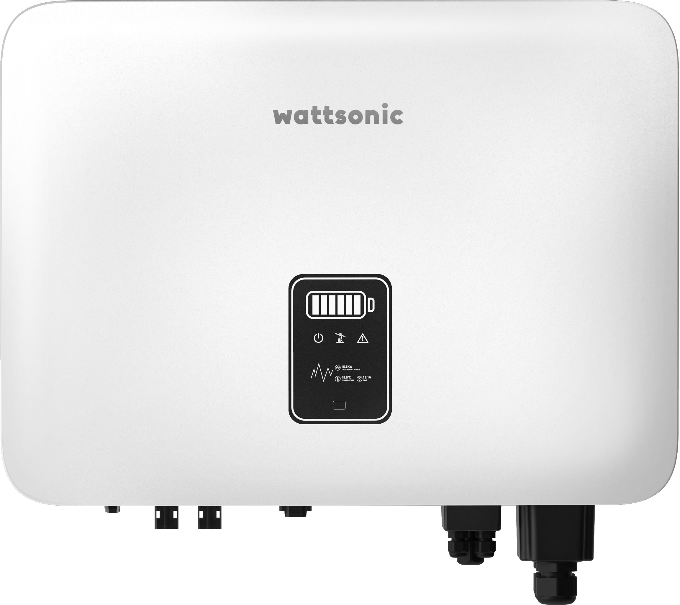
Wattsonic - Schmachtl Sun Energy Box
Wattsonic
Monitors Schmachtl Wattsonic hybrid inverter via Modbus RTU

Alnor HRU-P
Alnor Systemy Wentylacji Sp. z o. o.
Controls Alnor HRU-P heat recovery ventilation units via Modbus RTU.

Heidelberg Wallbox Energy Control
AMPERFIED GmbH
Controls and monitors Heidelberg Wallbox Energy Control EV charger via Modbus RTU.
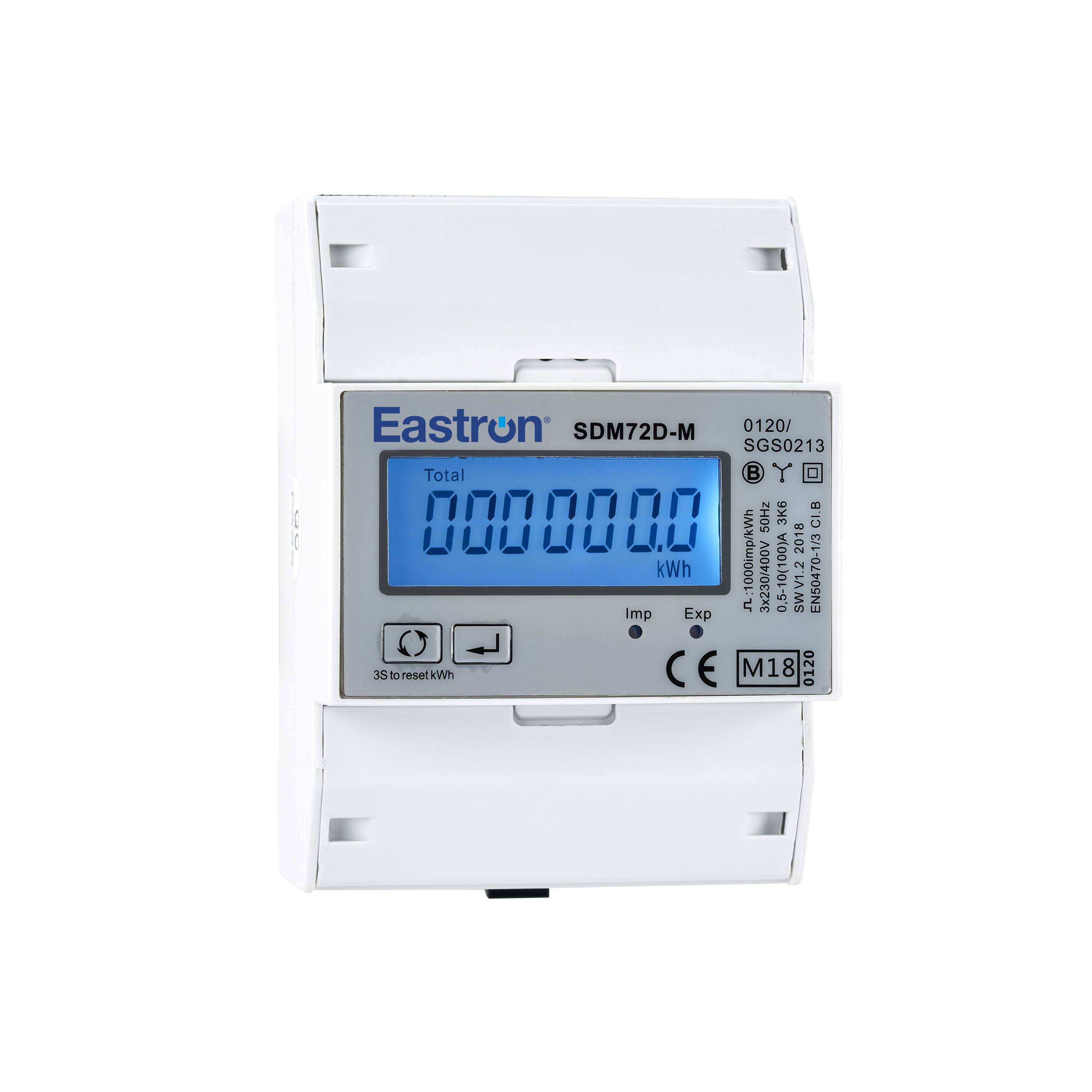
Eastron SDM72D-M
Eastron
Reads energy metering values from an Eastron SDM72D-M three-phase meter.