

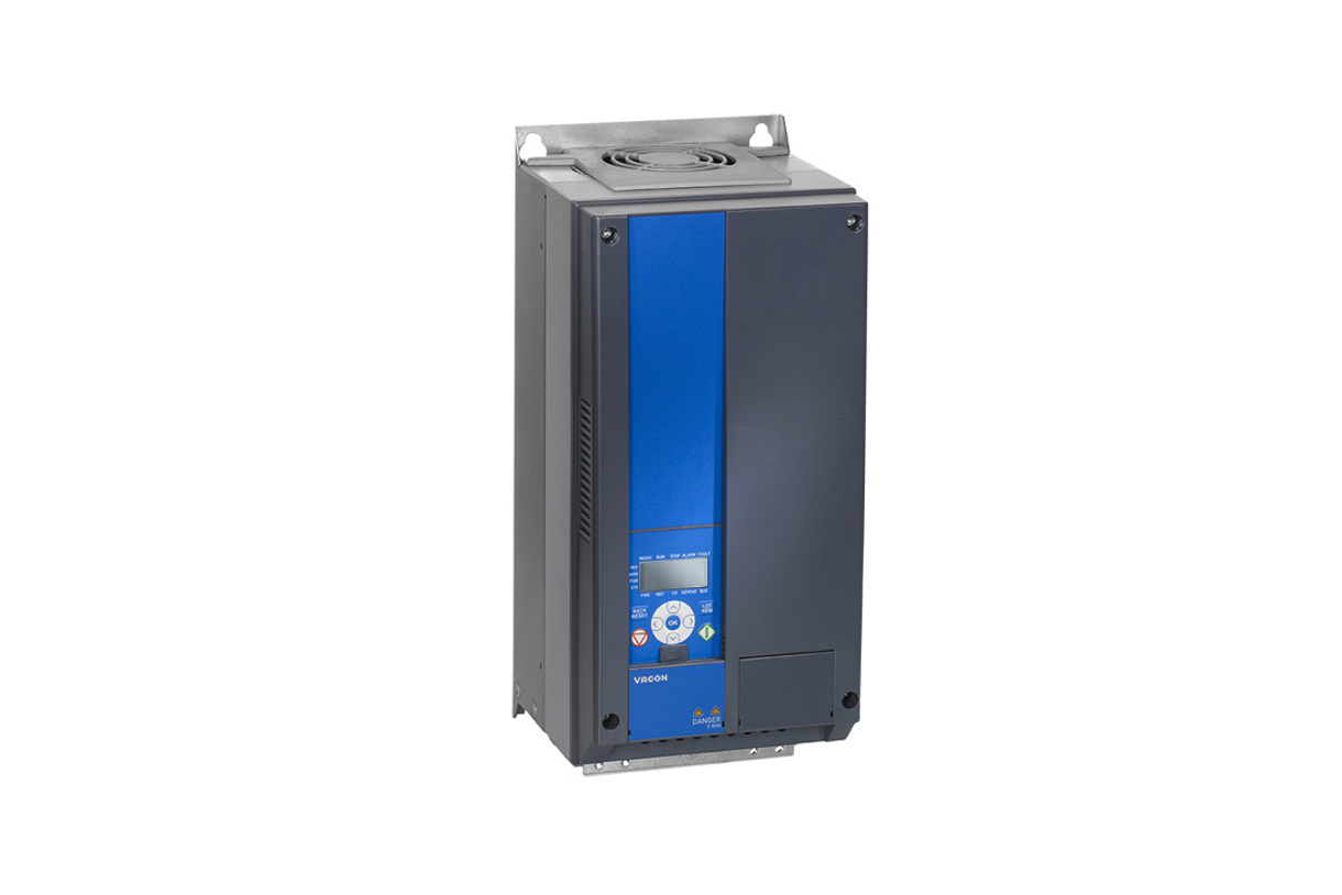
Vacon 20
Vacon
Compact AC drive with process data and every application parameter over Modbus RTU.
Overview
Key readings
- Status word
- Output frequency
- Motor speed
- Motor current
- Motor torque
- DC link voltage
Available commands
- Control word
- Speed reference
- Acceleration and deceleration time
- Min and max frequency
- PID setpoint
Use cases
- Get an alert when the fault bit of the status word goes to 1, so a pump stop does not go unnoticed.
- Log output frequency, motor current and DC link voltage to see how hard a fan or pump works over the day.
- Start, stop and set the speed reference of a drive from ModbusCloud during commissioning.
- Change the PID setpoint or the ramp times remotely without going to the cabinet.
- Compare motor current and torque of several drives on one dashboard to spot a worn bearing or a blocked impeller.
Installation
- 1Connect terminals A and B of the drive to the RS485 port of the ModbusCloud Gateway and ground the cable shield with the clamp. Switch on the termination resistor on the last drive of the line.
- 2Set P2.2 Fieldbus protocol to 1 (Modbus) and check P2.3 slave address, P2.4 baud rate and P2.6 parity (factory 1, 9600 baud, no parity).
- 3In ModbusCloud, add a Modbus device (RTU) with that address, 9600 baud, 8 data bits, no parity and 2 stop bits, and import this template.
- 4To control the drive over Modbus, set P2.1 control place to 1 (fieldbus) and the frequency reference P3.3 to 3 (fieldbus).
Things to watch for
- The drive does not answer.
- P2.2 Fieldbus protocol is 0 at the factory, which switches Modbus off. Set it to 1 and check address, baud rate and parity. With parity none the drive uses 2 stop bits, with even or odd 1 stop bit.
- Reads of several registers fail.
- The drive answers at most 11 consecutive IDs per request and every ID in the block must exist. Read gaps in the ID list as separate requests.
- Writing the control word has no effect.
- Fieldbus control only works when P2.1 control place is 1 (fieldbus). For the speed reference, P3.3 must also point to the fieldbus.
- Monitoring values look too large.
- The manual does not give the Modbus resolution of the monitoring values, so the template reads them raw. Use the process data registers from 2103 to 2111, which have a documented scale.
Registers (299)
299 read / 243 write
| Name | Address | Function | Type | Unit | Access |
|---|---|---|---|---|---|
| Monitor Output frequency | ••• | ••• | ••• | R | |
| Monitor Motor speed | ••• | ••• | ••• | R | |
| Monitor Motor current | ••• | ••• | ••• | R | |
| Monitor Motor torque | ••• | ••• | ••• | R | |
| Monitor Motor shaft power | ••• | ••• | ••• | R | |
| Monitor Motor voltage | ••• | ••• | ••• | R | |
| Monitor DC link voltage | ••• | ••• | ••• | R | |
| Monitor Unit temperature | ••• | ••• | ••• | R | |
| Monitor Motor temperature | ••• | ••• | ••• | R | |
| Monitor Digital input status DI1 to DI3 | ••• | ••• | ••• | R | |
| Monitor Digital input status DI4 to DI6 | ••• | ••• | ••• | R | |
| Monitor Relay and digital output status | ••• | ••• | ••• | R | |
| Monitor PID setpoint | ••• | ••• | ••• | R | |
| Monitor PID feedback value | ••• | ••• | ••• | R | |
| Monitor PID error | ••• | ••• | ••• | R | |
| Monitor PID output | ••• | ••• | ••• | R | |
| Monitor Frequency reference | ••• | ••• | ••• | R | |
| Monitor Process value | ••• | ••• | ••• | R | |
| Monitor Analog output E1 | ••• | ••• | ••• | R | |
| Monitor Analog output E2 | ••• | ••• | ••• | R | |
| Monitor DIE1 to DIE3 status | ••• | ••• | ••• | R | |
| Monitor DIE4 to DIE6 status | ••• | ••• | ••• | R | |
| Monitor DOE1 to DOE3 status | ••• | ••• | ••• | R | |
| Monitor DOE4 to DOE6 status | ••• | ••• | ••• | R | |
| Monitor Drive status word | ••• | ••• | ••• | R | |
| Monitor Temperature input 1 | ••• | ••• | ••• | R | |
| Monitor Temperature input 2 | ••• | ••• | ••• | R | |
| Monitor Temperature input 3 | ••• | ••• | ••• | R | |
| Monitor DIN status word | ••• | ••• | ••• | R | |
| Monitor Analog input 1 | ••• | ••• | ••• | R | |
| Monitor Analog input 2 | ••• | ••• | ••• | R | |
| Monitor Analog input E1 | ••• | ••• | ••• | R | |
| Monitor Output power | ••• | ••• | ••• | R | |
| Monitor Analog output | ••• | ••• | ••• | R | |
| Monitor Application status word | ••• | ••• | ••• | R | |
| Min frequency | ••• | ••• | ••• | Hz | R/W |
| Max frequency | ••• | ••• | ••• | Hz | R/W |
| Acceleration time 1 | ••• | ••• | ••• | s | R/W |
| Deceleration time 1 | ••• | ••• | ••• | s | R/W |
| Preset speed 1 | ••• | ••• | ••• | Hz | R/W |
| Preset speed 2 | ••• | ••• | ••• | Hz | R/W |
| Current limit | ••• | ••• | ••• | R/W | |
| U / f ratio | ••• | ••• | ••• | R/W | |
| Torque Boost | ••• | ••• | ••• | R/W | |
| Motor nominal voltage | ••• | ••• | ••• | V | R/W |
| Motor nominal frequency | ••• | ••• | ••• | Hz | R/W |
| Motor nominal speed | ••• | ••• | ••• | rpm | R/W |
| Motor nominal current | ••• | ••• | ••• | R/W | |
| Keypad stop button | ••• | ••• | ••• | R/W | |
| Parameter conceal | ••• | ••• | ••• | R/W | |
| Remote place 1 frequency reference selection | ••• | ••• | ••• | R/W | |
| PID P gain | ••• | ••• | ••• | % | R/W |
| PID I time | ••• | ••• | ••• | s | R/W |
| Motor cos phi | ••• | ••• | ••• | R/W | |
| Keypad control direction | ••• | ••• | ••• | R/W | |
| Preset speed 3 | ••• | ••• | ••• | Hz | R/W |
| Preset speed 4 | ••• | ••• | ••• | Hz | R/W |
| Preset speed 5 | ••• | ••• | ••• | Hz | R/W |
| Preset speed 6 | ••• | ••• | ••• | Hz | R/W |
| Preset speed 7 | ••• | ••• | ••• | Hz | R/W |
| Remote place 2 frequency reference selection | ••• | ••• | ••• | R/W | |
| PID D time | ••• | ••• | ••• | s | R/W |
| AIE1 filter time | ••• | ••• | ••• | s | R/W |
| AIE1 Signal range | ••• | ••• | ••• | R/W | |
| AIE1 Custom Min | ••• | ••• | ••• | % | R/W |
| AIE1 Custom Max | ••• | ••• | ••• | % | R/W |
| Fixed setpoint | ••• | ••• | ••• | % | R/W |
| Fixed setpoint 2 | ••• | ••• | ••• | % | R/W |
| Remote Control Place Selection | ••• | ••• | ••• | R/W | |
| Remote control place 2 selection | ••• | ••• | ••• | R/W | |
| Preset speed 0 | ••• | ••• | ••• | Hz | R/W |
| Preset alarm frequency | ••• | ••• | ••• | Hz | R/W |
| Local / Remote | ••• | ••• | ••• | R/W | |
| I/O start stop logic | ••• | ••• | ••• | R/W | |
| Analog output signal selection | ••• | ••• | ••• | R/W | |
| Analog output filter time | ••• | ••• | ••• | s | R/W |
| Analog output minimum | ••• | ••• | ••• | R/W | |
| Analog output scaling | ••• | ••• | ••• | % | R/W |
| DO1 signal selection | ••• | ••• | ••• | R/W | |
| RO1 signal selection | ••• | ••• | ••• | R/W | |
| RO2 signal selection | ••• | ••• | ••• | R/W | |
| Output frequency supervision function | ••• | ••• | ••• | R/W | |
| Output frequency supervision limit | ••• | ••• | ••• | Hz | R/W |
| DOE1 signal selection | ••• | ••• | ••• | R/W | |
| DOE2 signal selection | ••• | ••• | ••• | R/W | |
| Motor potentiometer ramp | ••• | ••• | ••• | R/W | |
| Setpoint source selection | ••• | ••• | ••• | R/W | |
| Feedback source selection | ••• | ••• | ••• | R/W | |
| Feedback value minimum | ••• | ••• | ••• | % | R/W |
| Feedback value maximum | ••• | ••• | ••• | % | R/W |
| PID error inversion | ••• | ••• | ••• | R/W | |
| Remote place frequency reference 2 | ••• | ••• | ••• | R/W | |
| Torque supervision function | ••• | ••• | ••• | R/W | |
| Torque supervision limit | ••• | ••• | ••• | % | R/W |
| Unit Temperature Supervision | ••• | ••• | ••• | R/W | |
| Unit Temperature Supervision Limit | ••• | ••• | ••• | °C | R/W |
| Analog input supervision signal | ••• | ••• | ••• | R/W | |
| AI supervision on level | ••• | ••• | ••• | % | R/W |
| AI supervision off level | ••• | ••• | ••• | % | R/W |
| Motor potentiometer reset | ••• | ••• | ••• | R/W | |
| AI1 filter time | ••• | ••• | ••• | s | R/W |
| AI1 Signal range | ••• | ••• | ••• | R/W | |
| AI1 Custom min | ••• | ••• | ••• | % | R/W |
| AI1 Custom max | ••• | ••• | ••• | % | R/W |
| AI2 filter time | ••• | ••• | ••• | s | R/W |
| AI2 signal range | ••• | ••• | ••• | R/W | |
| AI2 Custom min | ••• | ••• | ••• | % | R/W |
| AI2 Custom max | ••• | ••• | ••• | % | R/W |
| I/O control signal 1 | ••• | ••• | ••• | R/W | |
| I/O control signal 2 | ••• | ••• | ••• | R/W | |
| External fault close | ••• | ••• | ••• | R/W | |
| External fault open | ••• | ••• | ••• | R/W | |
| Run enable | ••• | ••• | ••• | R/W | |
| Ramp time 2 selection | ••• | ••• | ••• | R/W | |
| Reverse | ••• | ••• | ••• | R/W | |
| Fault reset | ••• | ••• | ••• | R/W | |
| Motor potentiometer down | ••• | ••• | ••• | R/W | |
| Motor potentiometer up | ••• | ••• | ••• | R/W | |
| Preset speed B0 | ••• | ••• | ••• | R/W | |
| Preset speed B1 | ••• | ••• | ••• | R/W | |
| Preset speed B2 | ••• | ••• | ••• | R/W | |
| Remote control place 2 | ••• | ••• | ••• | R/W | |
| RO1 ON delay | ••• | ••• | ••• | s | R/W |
| RO1 OFF delay | ••• | ••• | ••• | s | R/W |
| RO2 ON delay | ••• | ••• | ••• | s | R/W |
| RO2 OFF delay | ••• | ••• | ••• | s | R/W |
| Analog output E1 signal selection | ••• | ••• | ••• | R/W | |
| Analog output E1 filter time | ••• | ••• | ••• | s | R/W |
| Analog output E1 minimum | ••• | ••• | ••• | R/W | |
| Analog output E1 scaling | ••• | ••• | ••• | % | R/W |
| Analog output E2 signal selection | ••• | ••• | ••• | R/W | |
| Analog output E2 filter time | ••• | ••• | ••• | s | R/W |
| Analog output E2 minimum | ••• | ••• | ••• | R/W | |
| Analog output E2 scaling | ••• | ••• | ••• | % | R/W |
| Ramp S-shape 1 | ••• | ••• | ••• | s | R/W |
| Ramp S-shape 2 | ••• | ••• | ••• | s | R/W |
| Acceleration time 2 | ••• | ••• | ••• | s | R/W |
| Deceleration time 2 | ••• | ••• | ••• | s | R/W |
| Brake Chopper | ••• | ••• | ••• | R/W | |
| Start function | ••• | ••• | ••• | R/W | |
| Stop function | ••• | ••• | ••• | R/W | |
| DC Braking Current | ••• | ••• | ••• | R/W | |
| Stop DC current time | ••• | ••• | ••• | s | R/W |
| Prohibit Frequency Range 1 Low Limit | ••• | ••• | ••• | Hz | R/W |
| Prohibit Frequency Range 1 High Limit | ••• | ••• | ••• | Hz | R/W |
| Prohibit Frequency Range 2 Low Limit | ••• | ••• | ••• | Hz | R/W |
| Prohibit frequency range 2 high limit | ••• | ••• | ••• | Hz | R/W |
| Stop DC current frequency | ••• | ••• | ••• | Hz | R/W |
| Start DC current time | ••• | ••• | ••• | s | R/W |
| Flux braking current | ••• | ••• | ••• | R/W | |
| Flux Braking | ••• | ••• | ••• | R/W | |
| Sine filter | ••• | ••• | ••• | R/W | |
| Accel2 Frequency Threshold | ••• | ••• | ••• | Hz | R/W |
| Decel2 Frequency Threshold | ••• | ••• | ••• | Hz | R/W |
| I/f start enable | ••• | ••• | ••• | R/W | |
| I/f start frequency reference limit | ••• | ••• | ••• | % | R/W |
| I/f start current reference | ••• | ••• | ••• | % | R/W |
| Application Type | ••• | ••• | ••• | R/W | |
| Motor control mode | ••• | ••• | ••• | R/W | |
| Switching frequency | ••• | ••• | ••• | R/W | |
| Field weakening point | ••• | ••• | ••• | Hz | R/W |
| Field weakening point voltage | ••• | ••• | ••• | % | R/W |
| U / f mid point frequency | ••• | ••• | ••• | Hz | R/W |
| U / f mid point voltage | ••• | ••• | ••• | % | R/W |
| Zero freq voltage | ••• | ••• | ••• | % | R/W |
| Overvoltage controller | ••• | ••• | ••• | R/W | |
| Undervoltage controller | ••• | ••• | ••• | R/W | |
| Encoder pulses / revolution | ••• | ••• | ••• | R/W | |
| Motor identification | ••• | ••• | ••• | R/W | |
| Modulator type | ••• | ••• | ••• | R/W | |
| Motor type | ••• | ••• | ••• | R/W | |
| Rs voltage drop | ••• | ••• | ••• | % | R/W |
| Efficiency optimization | ••• | ••• | ••• | R/W | |
| Analog input low fault | ••• | ••• | ••• | R/W | |
| External fault | ••• | ••• | ••• | R/W | |
| Output Phase Fault | ••• | ••• | ••• | R/W | |
| Earth fault | ••• | ••• | ••• | R/W | |
| Motor thermal protection | ••• | ••• | ••• | R/W | |
| Motor thermal ambient temperature | ••• | ••• | ••• | °C | R/W |
| Motor thermal zero speed cooling | ••• | ••• | ••• | % | R/W |
| Motor thermal time constant | ••• | ••• | ••• | min | R/W |
| Stall protection | ••• | ••• | ••• | R/W | |
| Stall Current | ••• | ••• | ••• | A | R/W |
| Stall time | ••• | ••• | ••• | s | R/W |
| Stall frequency | ••• | ••• | ••• | Hz | R/W |
| Underload protection | ••• | ••• | ••• | R/W | |
| Underload field weakening load | ••• | ••• | ••• | % | R/W |
| Underload zero frequency load | ••• | ••• | ••• | % | R/W |
| Underload time limit | ••• | ••• | ••• | s | R/W |
| Wait time | ••• | ••• | ••• | s | R/W |
| Trial time | ••• | ••• | ••• | s | R/W |
| Restart function | ••• | ••• | ••• | R/W | |
| Under voltage fault | ••• | ••• | ••• | R/W | |
| Input phase fault | ••• | ••• | ••• | R/W | |
| Automatic Reset | ••• | ••• | ••• | R/W | |
| Thermistor Fault | ••• | ••• | ••• | R/W | |
| Fieldbus fault | ••• | ••• | ••• | R/W | |
| Temperature fault input | ••• | ••• | ••• | R/W | |
| Temperature fault | ••• | ••• | ••• | R/W | |
| Temperature fault limit | ••• | ••• | ••• | R/W | |
| Temperature fault mode | ••• | ••• | ••• | R/W | |
| Trials number | ••• | ••• | ••• | R/W | |
| Modbus communication status | ••• | ••• | ••• | R | |
| Fieldbus protocol | ••• | ••• | ••• | R/W | |
| Slave address | ••• | ••• | ••• | R/W | |
| Baud rate | ••• | ••• | ••• | R/W | |
| Parity type | ••• | ••• | ••• | R/W | |
| Communication time out | ••• | ••• | ••• | s | R/W |
| Reset communication status | ••• | ••• | ••• | R/W | |
| Parameters edit lock | ••• | ••• | ••• | R/W | |
| Power SW version | ••• | ••• | ••• | R | |
| API SW version | ••• | ••• | ••• | R | |
| Application ID | ••• | ••• | ••• | R | |
| Application revision | ••• | ••• | ••• | R | |
| System load | ••• | ••• | ••• | R | |
| FB Data Output 1 selection | ••• | ••• | ••• | R/W | |
| FB Data Output 2 selection | ••• | ••• | ••• | R/W | |
| FB Data Output 3 selection | ••• | ••• | ••• | R/W | |
| FB data output 4 selection | ••• | ••• | ••• | R/W | |
| FB Data Output 5 selection | ••• | ••• | ••• | R/W | |
| FB Data Output 6 selection | ••• | ••• | ••• | R/W | |
| FB Data Output 7 selection | ••• | ••• | ••• | R/W | |
| FB Data Output 8 selection | ••• | ••• | ••• | R/W | |
| Sleep minimum frequency | ••• | ••• | ••• | Hz | R/W |
| Sleep delay | ••• | ••• | ••• | s | R/W |
| Wake up error | ••• | ••• | ••• | % | R/W |
| Process unit minimum value | ••• | ••• | ••• | R/W | |
| Process unit maximum value | ••• | ••• | ••• | R/W | |
| Process unit decimal digits | ••• | ••• | ••• | R/W | |
| Motor preheat active | ••• | ••• | ••• | R/W | |
| PID setpoint 2 | ••• | ••• | ••• | R/W | |
| Sleep setpoint boost | ••• | ••• | ••• | % | R/W |
| Setpoint boost time | ••• | ••• | ••• | s | R/W |
| Voltage limiter enable | ••• | ••• | ••• | R/W | |
| Config DI5 and DI6 | ••• | ••• | ••• | R/W | |
| Aux CW data in selection | ••• | ••• | ••• | R/W | |
| Temperature unit | ••• | ••• | ••• | R/W | |
| Quick stop open | ••• | ••• | ••• | R/W | |
| Motor preheat function | ••• | ••• | ••• | R/W | |
| Motor preheat current | ••• | ••• | ••• | R/W | |
| Min pulse frequency | ••• | ••• | ••• | Hz | R/W |
| Max pulse frequency | ••• | ••• | ••• | Hz | R/W |
| Frequency reference at min pulse frequency | ••• | ••• | ••• | Hz | R/W |
| Frequency reference at max pulse frequency | ••• | ••• | ••• | Hz | R/W |
| Encoder direction | ••• | ••• | ••• | R/W | |
| Monitor Pulse train encoder input | ••• | ••• | ••• | R | |
| Monitor Encoder speed | ••• | ••• | ••• | R | |
| Quick stop deceleration time | ••• | ••• | ••• | s | R/W |
| Brake chopper level | ••• | ••• | ••• | V | R/W |
| DOE3 signal selection | ••• | ••• | ••• | R/W | |
| DOE4 signal selection | ••• | ••• | ••• | R/W | |
| DOE5 signal selection | ••• | ••• | ••• | R/W | |
| DOE6 signal selection | ••• | ••• | ••• | R/W | |
| Analog input low fault delay | ••• | ••• | ••• | s | R/W |
| Temperature supervision input | ••• | ••• | ••• | R/W | |
| Temperature supervision function | ••• | ••• | ••• | R/W | |
| Temperature supervision limit | ••• | ••• | ••• | R/W | |
| FWD REV conflict supervision | ••• | ••• | ••• | R/W | |
| Start delay time | ••• | ••• | ••• | s | R/W |
| Keypad reverse enable | ••• | ••• | ••• | R/W | |
| Sleep maximum loss | ••• | ••• | ••• | % | R/W |
| Sleep loss check time | ••• | ••• | ••• | s | R/W |
| Process unit source select | ••• | ••• | ••• | R/W | |
| External brake open frequency limit | ••• | ••• | ••• | Hz | R/W |
| External brake close frequency limit | ••• | ••• | ••• | Hz | R/W |
| External brake close frequency limit reverse | ••• | ••• | ••• | Hz | R/W |
| External brake open delay | ••• | ••• | ••• | s | R/W |
| External brake open close current limit | ••• | ••• | ••• | % | R/W |
| RO1 inversion | ••• | ••• | ••• | R/W | |
| RO2 inversion | ••• | ••• | ••• | R/W | |
| Temperature min value | ••• | ••• | ••• | R/W | |
| Temperature max value | ••• | ••• | ••• | R/W | |
| FB control word | ••• | ••• | ••• | R/W | |
| FB general control word | ••• | ••• | ••• | R/W | |
| FB speed reference | ••• | ••• | ••• | % | R/W |
| FB data in 1 | ••• | ••• | ••• | R/W | |
| FB data in 2 | ••• | ••• | ••• | R/W | |
| FB data in 3 | ••• | ••• | ••• | R/W | |
| FB data in 4 | ••• | ••• | ••• | R/W | |
| FB data in 5 | ••• | ••• | ••• | R/W | |
| FB data in 6 | ••• | ••• | ••• | R/W | |
| FB data in 7 | ••• | ••• | ••• | R/W | |
| FB data in 8 | ••• | ••• | ••• | R/W | |
| FB status word | ••• | ••• | ••• | R | |
| FB general status word | ••• | ••• | ••• | R | |
| FB actual speed | ••• | ••• | ••• | % | R |
| FB data out 1 | ••• | ••• | ••• | R | |
| FB data out 2 | ••• | ••• | ••• | Hz | R |
| FB data out 3 | ••• | ••• | ••• | rpm | R |
| FB data out 4 | ••• | ••• | ••• | V | R |
| FB data out 5 | ••• | ••• | ••• | % | R |
| FB data out 6 | ••• | ••• | ••• | A | R |
| FB data out 7 | ••• | ••• | ••• | % | R |
| FB data out 8 | ••• | ••• | ••• | V | R |
| API SW ID | ••• | ••• | ••• | R | |
| Power SW ID | ••• | ••• | ••• | R | |
| Application access password | ••• | ••• | ••• | R/W | |
| Keypad button lock | ••• | ••• | ••• | R/W | |
| Motor temperature memory mode | ••• | ••• | ••• | R/W |
Loading registers…
Read the Vacon 20 remotely
We load the templates onto the gateway and set up your portal, you connect it at your customer's site. Tell us briefly what you need and we'll send a proposal.
From €295 + €149/year.
Prefer to configure it yourself? Order the gateway in the shop·Or see the live demo first
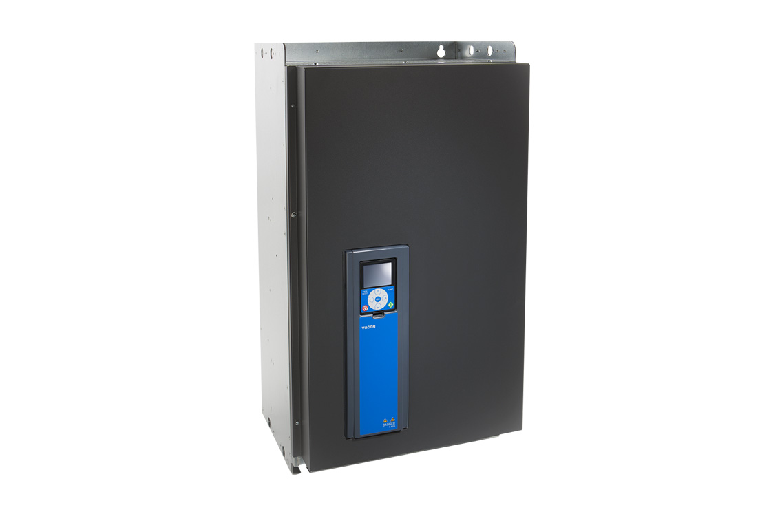
More Vacon templates
More RTU templates

Alnor HRU
Alnor Systemy Wentylacji Sp. z o. o.
Controls and monitors Alnor heat recovery ventilation units via Modbus RTU.

Alnor HRU-P
Alnor Systemy Wentylacji Sp. z o. o.
Controls Alnor HRU-P heat recovery ventilation units via Modbus RTU.

connecdoor.controller
connecdoor
Controls and monitors smart door access points via RS485
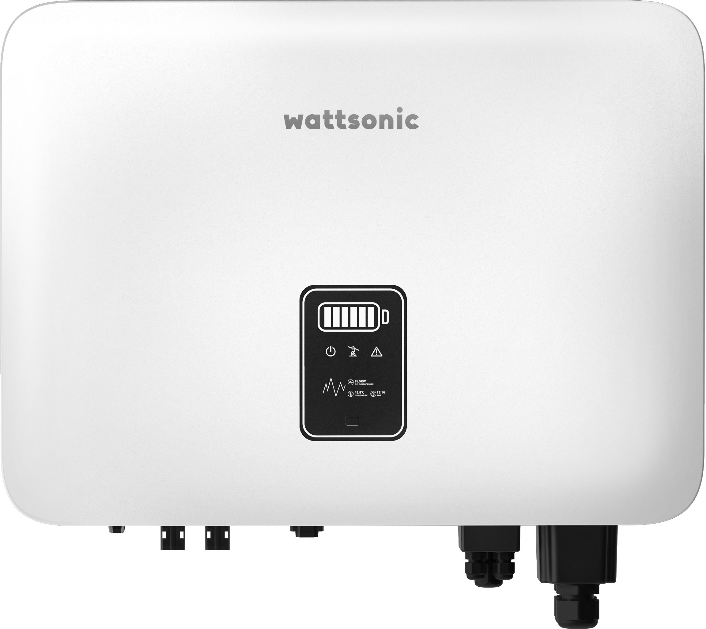
Wattsonic - Schmachtl Sun Energy Box
Wattsonic
Monitors Schmachtl Wattsonic hybrid inverter via Modbus RTU

Heidelberg Wallbox Energy Control
AMPERFIED GmbH
Controls and monitors Heidelberg Wallbox Energy Control EV charger via Modbus RTU.
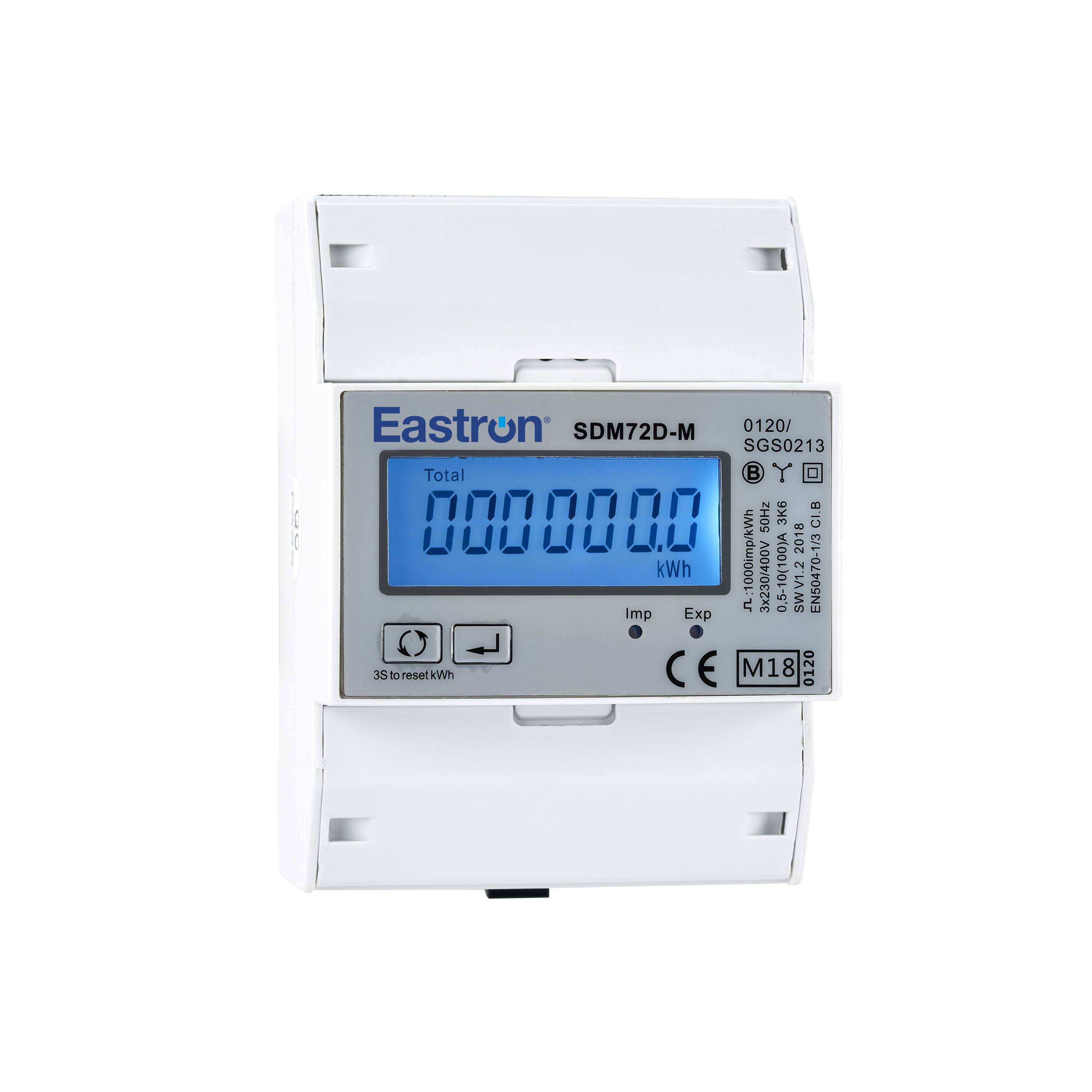
Eastron SDM72D-M
Eastron
Reads energy metering values from an Eastron SDM72D-M three-phase meter.