
Vents A21
Automation for Vents heat recovery units with air quality control, heaters, bypass and weekly schedule.
The Vents A21 is the automation of Vents heat recovery units that controls the fans, heaters, bypass and air quality ventilation in homes and small buildings. This Modbus RTU template reads temperatures, humidity, CO2, airflow, filter state and alarms and lets you switch the unit, change speed and mode and set setpoints and schedules from ModbusCloud.
- Protocol
- Modbus RTU
- Connection
- RS485, 115200 baud
- Registers
- 327, read and write
- Brand
- Vents
- Key readings
- Supply air temperature · Extract air temperature · Outdoor temperature · Humidity · CO2 · Supply and exhaust airflow · Filter state · Active alarms
- Available commands
- On and off · Speed · Operation mode · Temperature setpoint · Weekly schedule
- Compatible models
- A21 · VUT EC A21 · VUTR EC A21 · VUE EC A21
- Last updated
Registers (327)
324 read, 185 write
| Name | Unit | Access | Address (Hidden until you enter your email) | Function (hidden) | Type (hidden) |
|---|---|---|---|---|---|
| Control Temperature | °C | Read | |||
| Outdoor Air Temperature Before Preheater | °C | Read | |||
| Supply Air Temperature | °C | Read | |||
| Extract Air Temperature | °C | Read | |||
| Exhaust Air Temperature | °C | Read | |||
| Outdoor Temperature Panel Sensor | °C | Read | |||
| Supply Temperature After Preheater | °C | Read | |||
| Supply Temperature Before Reheater | °C | Read | |||
| Return Water Temperature | °C | Read | |||
| RTC Battery Voltage | mV | Read | |||
| Main Humidity | %RH | Read | |||
| External Humidity | %RH | Read | |||
| Main CO2 | ppm | Read | |||
| External CO2 | ppm | Read | |||
| Main PM2.5 | Read | ||||
| External PM2.5 | Read | ||||
| Main VOC | % | Read | |||
| External VOC | % | Read | |||
| External 0-10 V Signal | % | Read | |||
| Supply Airflow | m³/h | Read | |||
| Exhaust Airflow | m³/h | Read | |||
| Supply Duct Pressure | Pa | Read | |||
| Exhaust Duct Pressure | Pa | Read | |||
| Supply Fan Speed | rpm | Read | |||
| Extract Fan Speed | rpm | Read | |||
| Main Timer Remaining Min Sec | Read | ||||
| Main Timer Remaining Hours | Read | ||||
| Filter Timer Hours Minutes | Read | ||||
| Filter Timer Days | d | Read | |||
| Motor Hours Hours Minutes | Read | ||||
| Motor Hours Days | d | Read | |||
| Filter State | Read | ||||
| Weekly Schedule Speed | Read | ||||
| Weekly Schedule Temperature Setpoint | °C | Read | |||
| Firmware Version | Read | ||||
| Firmware Date Day Month | Read | ||||
| Firmware Date Year | Read | ||||
| Device Type | Read | ||||
| Alarm Status | Read | ||||
| Humidity PID Output | % | Read | |||
| CO2 PID Output | % | Read | |||
| PM2.5 PID Output | % | Read | |||
| VOC PID Output | % | Read | |||
| Preheater PID Output | % | Read | |||
| Reheater PID Output | % | Read | |||
| Bypass Rotor PID Output | % | Read | |||
| Condensing Unit PID Output | % | Read | |||
| Return Water PID Output | % | Read | |||
| Supply Air Setpoint Calculated | °C | Read | |||
| Return Water Standby Setpoint | °C | Read | |||
| Return Water Start Setpoint | °C | Read | |||
| Bypass Rotor Position | % | Read | |||
| Supply Fan Output | % | Read | |||
| Extract Fan Output | % | Read | |||
| Boost Switch Input | Read | ||||
| Fireplace Switch Input | Read | ||||
| Fire Alarm Input | Read | ||||
| Humidity Setpoint Exceeded | Read | ||||
| CO2 Setpoint Exceeded | Read | ||||
| PM2.5 Setpoint Exceeded | Read | ||||
| VOC Setpoint Exceeded | Read | ||||
| Heater Running | Read | ||||
| Cooler Running | Read | ||||
| Electric Heater Blowdown | Read | ||||
| Preheater Thermostat Input | Read | ||||
| Reheater Thermostat Input | Read | ||||
| Supply Filter Pressure Switch | Read | ||||
| Extract Filter Pressure Switch | Read | ||||
| Water Pressure Sensor Input | Read | ||||
| Water Flow Sensor Input | Read | ||||
| Supply Fan Pressure Switch | Read | ||||
| Extract Fan Pressure Switch | Read | ||||
| Return Water Preheating | Read | ||||
| Alarm Code 0 | Read | ||||
| Alarm Code 1 | Read | ||||
| Alarm Code 2 | Read | ||||
| Alarm Code 3 | Read | ||||
| Alarm Code 4 | Read | ||||
| Alarm Code 5 | Read | ||||
| Alarm Code 6 | Read | ||||
| Alarm Code 7 | Read | ||||
| Alarm Code 8 | Read | ||||
| Alarm Code 9 | Read | ||||
| Alarm Code 10 | Read | ||||
| Alarm Code 11 | Read | ||||
| Alarm Code 12 | Read | ||||
| Alarm Code 13 | Read | ||||
| Alarm Code 14 | Read | ||||
| Alarm Code 15 | Read | ||||
| Alarm Code 16 | Read | ||||
| Alarm Code 17 | Read | ||||
| Alarm Code 18 | Read | ||||
| Alarm Code 19 | Read | ||||
| Alarm Code 20 | Read | ||||
| Alarm Code 21 | Read | ||||
| Alarm Code 22 | Read | ||||
| Alarm Code 23 | Read | ||||
| Alarm Code 24 | Read | ||||
| Alarm Code 25 | Read | ||||
| Alarm Code 26 | Read | ||||
| Alarm Code 27 | Read | ||||
| Alarm Code 28 | Read | ||||
| Alarm Code 29 | Read | ||||
| Alarm Code 30 | Read | ||||
| Alarm Code 31 | Read | ||||
| Alarm Code 32 | Read | ||||
| Alarm Code 33 | Read | ||||
| Alarm Code 34 | Read | ||||
| Alarm Code 35 | Read | ||||
| Alarm Code 36 | Read | ||||
| Alarm Code 37 | Read | ||||
| Alarm Code 38 | Read | ||||
| Alarm Code 39 | Read | ||||
| Alarm Code 40 | Read | ||||
| Alarm Code 41 | Read | ||||
| Alarm Code 42 | Read | ||||
| Alarm Code 43 | Read | ||||
| Alarm Code 44 | Read | ||||
| Alarm Code 45 | Read | ||||
| Alarm Code 46 | Read | ||||
| Alarm Code 47 | Read | ||||
| Alarm Code 48 | Read | ||||
| Alarm Code 49 | Read | ||||
| Alarm Code 50 | Read | ||||
| Alarm Code 51 | Read | ||||
| Alarm Code 52 | Read | ||||
| Unit On Off | Read and write | ||||
| Main Timer | Read and write | ||||
| Weekly Schedule | Read and write | ||||
| Boost Mode Active | Read | ||||
| Fireplace Mode Active | Read | ||||
| Main Humidity Sensor Enable | Read and write | ||||
| External Humidity Sensor Enable | Read and write | ||||
| Main CO2 Sensor Enable | Read and write | ||||
| External CO2 Sensor Enable | Read and write | ||||
| Main PM2.5 Sensor Enable | Read and write | ||||
| External PM2.5 Sensor Enable | Read and write | ||||
| Main VOC Sensor Enable | Read and write | ||||
| External VOC Sensor Enable | Read and write | ||||
| Boost Switch Input Enable | Read and write | ||||
| Fireplace Switch Input Enable | Read and write | ||||
| Fire Alarm Sensor Enable | Read and write | ||||
| External 0-10 V Control Enable | Read and write | ||||
| Reset Filter Timer | Write | ||||
| Reset Alarms | Write | ||||
| Restore Factory Settings | Write | ||||
| Cloud Control Enable | Read and write | ||||
| Minimum Supply Air Temperature Control | Read and write | ||||
| Water Pressure Sensor Enable | Read and write | ||||
| Water Flow Sensor Enable | Read and write | ||||
| Water Heater Auto Restart | Read and write | ||||
| Auto Airflow Reduction On Heater Fault | Read and write | ||||
| Ventilation Mode | Read | ||||
| Maximum Speed Number | Read | ||||
| Speed Number | Read and write | ||||
| Minimum Fan Speed | % | Read | |||
| Maximum Fan Speed | % | Read | |||
| Supply Fan Speed Standby | % | Read and write | |||
| Extract Fan Speed Standby | % | Read and write | |||
| Supply Fan Speed Speed 1 | % | Read and write | |||
| Extract Fan Speed Speed 1 | % | Read and write | |||
| Supply Fan Speed Speed 2 | % | Read and write | |||
| Extract Fan Speed Speed 2 | % | Read and write | |||
| Supply Fan Speed Speed 3 | % | Read and write | |||
| Extract Fan Speed Speed 3 | % | Read and write | |||
| Supply Fan Speed Speed 4 | % | Read and write | |||
| Extract Fan Speed Speed 4 | % | Read and write | |||
| Supply Fan Speed Speed 5 | % | Read and write | |||
| Extract Fan Speed Speed 5 | % | Read and write | |||
| Manual Fan Speed | % | Read and write | |||
| Heater Blowdown Fan Speed | % | Read and write | |||
| Boost Supply Fan Speed | % | Read and write | |||
| Boost Extract Fan Speed | % | Read and write | |||
| Fireplace Supply Fan Speed | % | Read and write | |||
| Fireplace Extract Fan Speed | % | Read and write | |||
| Minimum Airflow | m³/h | Read | |||
| Maximum Airflow | m³/h | Read | |||
| Supply Airflow Standby | m³/h | Read and write | |||
| Extract Airflow Standby | m³/h | Read and write | |||
| Supply Airflow Speed 1 | m³/h | Read and write | |||
| Extract Airflow Speed 1 | m³/h | Read and write | |||
| Supply Airflow Speed 2 | m³/h | Read and write | |||
| Extract Airflow Speed 2 | m³/h | Read and write | |||
| Supply Airflow Speed 3 | m³/h | Read and write | |||
| Extract Airflow Speed 3 | m³/h | Read and write | |||
| Supply Airflow Speed 4 | m³/h | Read and write | |||
| Extract Airflow Speed 4 | m³/h | Read and write | |||
| Supply Airflow Speed 5 | m³/h | Read and write | |||
| Extract Airflow Speed 5 | m³/h | Read and write | |||
| Minimum Duct Pressure | Pa | Read | |||
| Maximum Duct Pressure | Pa | Read | |||
| Supply Pressure Standby | Pa | Read and write | |||
| Exhaust Pressure Standby | Pa | Read and write | |||
| Supply Pressure Speed 1 | Pa | Read and write | |||
| Exhaust Pressure Speed 1 | Pa | Read and write | |||
| Operation Mode | Read and write | ||||
| Room Temperature Setpoint | °C | Read and write | |||
| Humidity Setpoint | %RH | Read and write | |||
| CO2 Setpoint | ppm | Read and write | |||
| PM2.5 Setpoint | Read and write | ||||
| VOC Setpoint | % | Read and write | |||
| Timer Mode Speed | Read and write | ||||
| Timer Temperature Setpoint | °C | Read and write | |||
| Timer Duration Hours Minutes | Read and write | ||||
| Winter Summer Changeover Temperature | °C | Read and write | |||
| Control Temperature Sensor | Read and write | ||||
| Main Heater Type | Read and write | ||||
| Cooler Type | Read and write | ||||
| Frost Protection Mode | Read and write | ||||
| Bypass Rotor Type | Read | ||||
| Filter Timer Setpoint | d | Read and write | |||
| Boost Off Delay | min | Read and write | |||
| Boost On Delay | min | Read and write | |||
| RTC Minutes Seconds | Read and write | ||||
| RTC Hours | Read and write | ||||
| RTC Day Weekday | Read and write | ||||
| RTC Month Year | Read and write | ||||
| Main CO2 Sensor Range | ppm | Read and write | |||
| Main PM2.5 Sensor Range | Read and write | ||||
| Minimum Supply Air Temperature | °C | Read and write | |||
| Main Heater Mode | Read and write | ||||
| Main Heater Manual Output | % | Read and write | |||
| Cooler Mode | Read and write | ||||
| Cooler Manual Output | % | Read and write | |||
| Preheater Mode | Read and write | ||||
| Preheater Manual Output | % | Read and write | |||
| Bypass Rotor Mode | Read and write | ||||
| Bypass Rotor Manual Output | % | Read and write | |||
| Humidity PID Kp | Read and write | ||||
| Humidity PID Ki | Read and write | ||||
| Humidity PID Kd | Read and write | ||||
| CO2 PID Kp | Read and write | ||||
| CO2 PID Ki | Read and write | ||||
| CO2 PID Kd | Read and write | ||||
| PM2.5 PID Kp | Read and write | ||||
| PM2.5 PID Ki | Read and write | ||||
| PM2.5 PID Kd | Read and write | ||||
| VOC PID Kp | Read and write | ||||
| VOC PID Ki | Read and write | ||||
| VOC PID Kd | Read and write | ||||
| Preheater PID Kp | Read and write | ||||
| Preheater PID Ki | Read and write | ||||
| Preheater PID Kd | Read and write | ||||
| Reheater PID Kp | Read and write | ||||
| Reheater PID Ki | Read and write | ||||
| Reheater PID Kd | Read and write | ||||
| Bypass Rotor PID Kp | Read and write | ||||
| Bypass Rotor PID Ki | Read and write | ||||
| Bypass Rotor PID Kd | Read and write | ||||
| Condensing Unit PID Kp | Read and write | ||||
| Condensing Unit PID Ki | Read and write | ||||
| Condensing Unit PID Kd | Read and write | ||||
| Return Water PID Kp | Read and write | ||||
| Return Water PID Ki | Read and write | ||||
| Return Water PID Kd | Read and write | ||||
| Fan Alarm Control Type | Read | ||||
| Fan Alarm Detection Time | s | Read | |||
| Damper Opening Time | s | Read and write | |||
| Heater Blowdown Time | s | Read and write | |||
| Condensing Unit Minimum Off Time | min | Read and write | |||
| Condensing Unit Minimum On Time | min | Read and write | |||
| Condensing Unit Hysteresis | °C | Read and write | |||
| Bypass Location | Read | ||||
| Bypass Opening Time | s | Read | |||
| Outdoor Inlet Sensor Correction | °C | Read and write | |||
| Supply Outlet Sensor Correction | °C | Read and write | |||
| Extract Inlet Sensor Correction | °C | Read and write | |||
| Exhaust Outlet Sensor Correction | °C | Read and write | |||
| Return Water Sensor Correction | °C | Read and write | |||
| Outdoor Sensor Correction | °C | Read and write | |||
| Water Valve Minimum Position | % | Read and write | |||
| Return Water Start Alarm Time | min | Read and write | |||
| Return Water Start Temp Warm | °C | Read and write | |||
| Return Water Start Temp Cold | °C | Read and write | |||
| Return Water Frost Alarm Temp Warm | °C | Read and write | |||
| Return Water Frost Alarm Temp Cold | °C | Read and write | |||
| Engineering Menu Password | Read and write | ||||
| Monday Period 1 Speed Temperature | Read and write | ||||
| Monday Period 1 End Time | Read and write | ||||
| Monday Period 2 Speed Temperature | Read and write | ||||
| Monday Period 2 End Time | Read and write | ||||
| Monday Period 3 Speed Temperature | Read and write | ||||
| Monday Period 3 End Time | Read and write | ||||
| Monday Period 4 Speed Temperature | Read and write | ||||
| Tuesday Period 1 Speed Temperature | Read and write | ||||
| Tuesday Period 1 End Time | Read and write | ||||
| Tuesday Period 2 Speed Temperature | Read and write | ||||
| Tuesday Period 2 End Time | Read and write | ||||
| Tuesday Period 3 Speed Temperature | Read and write | ||||
| Tuesday Period 3 End Time | Read and write | ||||
| Tuesday Period 4 Speed Temperature | Read and write | ||||
| Wednesday Period 1 Speed Temperature | Read and write | ||||
| Wednesday Period 1 End Time | Read and write | ||||
| Wednesday Period 2 Speed Temperature | Read and write | ||||
| Wednesday Period 2 End Time | Read and write | ||||
| Wednesday Period 3 Speed Temperature | Read and write | ||||
| Wednesday Period 3 End Time | Read and write | ||||
| Wednesday Period 4 Speed Temperature | Read and write | ||||
| Thursday Period 1 Speed Temperature | Read and write | ||||
| Thursday Period 1 End Time | Read and write | ||||
| Thursday Period 2 Speed Temperature | Read and write | ||||
| Thursday Period 2 End Time | Read and write | ||||
| Thursday Period 3 Speed Temperature | Read and write | ||||
| Thursday Period 3 End Time | Read and write | ||||
| Thursday Period 4 Speed Temperature | Read and write | ||||
| Friday Period 1 Speed Temperature | Read and write | ||||
| Friday Period 1 End Time | Read and write | ||||
| Friday Period 2 Speed Temperature | Read and write | ||||
| Friday Period 2 End Time | Read and write | ||||
| Friday Period 3 Speed Temperature | Read and write | ||||
| Friday Period 3 End Time | Read and write | ||||
| Friday Period 4 Speed Temperature | Read and write | ||||
| Saturday Period 1 Speed Temperature | Read and write | ||||
| Saturday Period 1 End Time | Read and write | ||||
| Saturday Period 2 Speed Temperature | Read and write | ||||
| Saturday Period 2 End Time | Read and write | ||||
| Saturday Period 3 Speed Temperature | Read and write | ||||
| Saturday Period 3 End Time | Read and write | ||||
| Saturday Period 4 Speed Temperature | Read and write | ||||
| Sunday Period 1 Speed Temperature | Read and write | ||||
| Sunday Period 1 End Time | Read and write | ||||
| Sunday Period 2 Speed Temperature | Read and write | ||||
| Sunday Period 2 End Time | Read and write | ||||
| Sunday Period 3 Speed Temperature | Read and write | ||||
| Sunday Period 3 End Time | Read and write | ||||
| Sunday Period 4 Speed Temperature | Read and write | ||||
| Frost Protection Exhaust Setpoint | °C | Read |
Loading registers…
Send your device list
If a device is not in the library yet, we build the template for free as soon as we have the register data.
Use cases
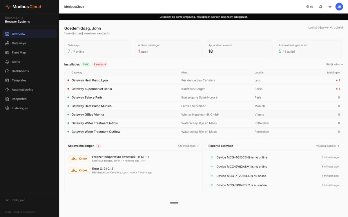
- Show supply temperature, CO2 and airflow of every ventilation unit on one ModbusCloud dashboard.
- Get an email alert when the alarm status is not 0 or the filter state reports a clogged filter.
- Keep a history of humidity and CO2 per home to show residents how ventilation responds.
- Switch a unit to a higher speed from ModbusCloud when a building is busy.
- Change the weekly schedule or temperature setpoint remotely without visiting the site.
Installation
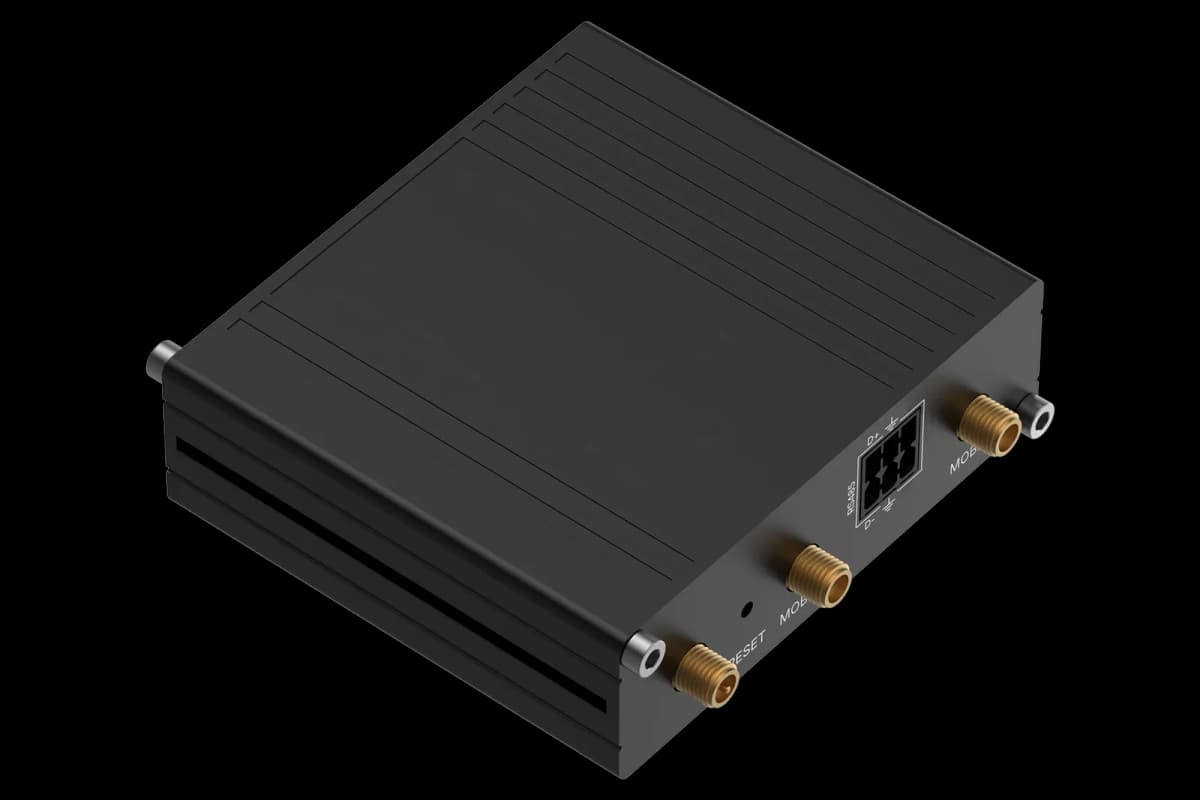
Remove wired control panels from the RS-485 bus of the unit, then connect A and B of that bus to the ModbusCloud Gateway, with termination at the bus end.
In the Vents app, check the Modbus RTU address (1 to 16) and serial settings, factory 115200 baud, no parity, 2 stop bits.
In ModbusCloud, add a Modbus RTU device with that address and these serial settings and import this template.
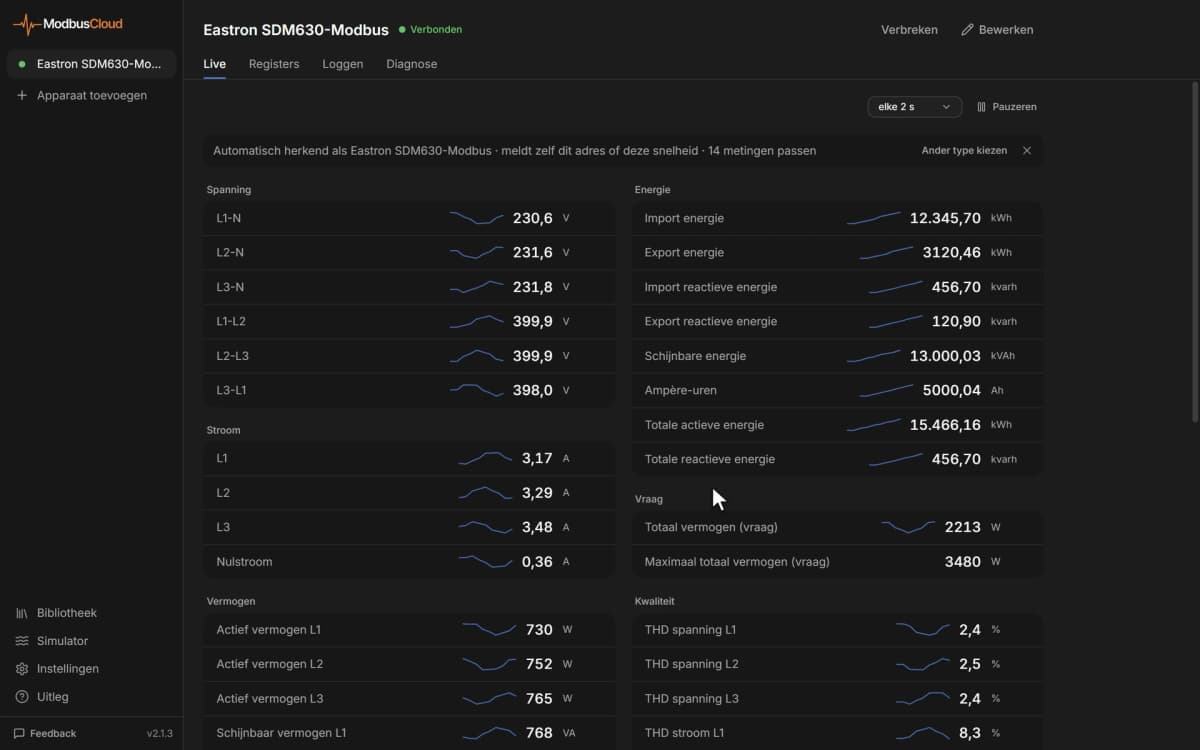
Check that Supply Air Temperature and Supply Airflow match the values in the Vents app.
Things to watch for
The unit does not answer. What should I check?
Make sure no wired control panel is still connected to the same RS-485 bus, since Modbus RTU only works there without panels. Check address, baud rate (115200 from the factory), parity and stop bits, swap A and B if needed and add termination on a long bus.
Why do some values show -32768 or 32767?
Temperatures are sent in tenths of a degree. The value -32768 means the sensor is not connected and 32767 means a short circuit. Humidity, CO2, PM2.5 and VOC read 0 when that sensor is missing.
How do I read timers and the clock?
Timers, motor hours, firmware date, clock and the weekly schedule pack two values in one register, one per byte. The register comment says which values share the register; check on the unit which byte holds which value.
Why is my speed or setpoint change not kept?
The main timer, weekly schedule, boost and fireplace modes override the selected speed. Switch the weekly schedule or timer off with their coils first, and write the speed number 1 to 5 or 255 for manual speed. Writes act on the unit immediately.
Can I use Modbus TCP instead?
Yes. Connect the unit to the network over Ethernet or Wi-Fi, set a static address in the Vents app and add a Modbus TCP device on port 502 in ModbusCloud. Wired control panels can then stay on RS-485.




Want to see how it works?