









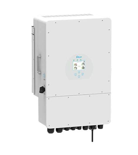
Deye 3p hybrid inverter (battery)
The Deye 3p hybrid inverter is a three-phase solar hybrid inverter with integrated battery management, designed for residential and commercial PV storage systems. This Modbus RTU template reads battery power flow (charge and discharge), cumulative energy, and state of charge from the inverter. It also exposes a full set of write registers covering the system work mode, grid charge enable, solar sell enable, maximum charge current, and all six Time-of-Use minimum SOC slots. Together these give your ModbusCloud portal both live battery visibility and remote control over charging strategy.
- Protocol
- Modbus RTU
- Connection
- RS485
- Registers
- 14, read and write
- Brand
- Deye
- Compatible models
- 3p hybrid inverter
- Last updated
Registers (14)
3 read, 11 write
| Name | Unit | Access | Address (Hidden until you enter your email) | Function (hidden) | Type (hidden) |
|---|---|---|---|---|---|
| power | W | Read | |||
| energy | Wh | Read | |||
| soc | % | Read | |||
| batterymode_a | Write | ||||
| batterymode_b | % | Write | |||
| batterymode_c | % | Write | |||
| batterymode_d | % | Write | |||
| batterymode_e | % | Write | |||
| batterymode_f | % | Write | |||
| batterymode_g | % | Write | |||
| batterymode_h | Write | ||||
| batterymode_i | Write | ||||
| batterymode_j | Write | ||||
| batterymode_t | A | Write |
Loading registers…
Send your device list
If a device is not in the library yet, we build the template for free as soon as we have the register data.
Use cases
- Monitor battery state of charge in real time to verify storage is available before evening peak demand.
- Track cumulative battery energy to detect unexpected throughput changes across weeks or months.
- Alert on sustained battery discharge power above a threshold to catch load imbalances early.
- Compare charge and discharge power readings across multiple sites to benchmark storage utilisation.
- Verify that Time-of-Use minimum SOC setpoints were applied correctly after a remote schedule change.
Installation
Enable Modbus RTU on the Deye 3p hybrid inverter via the LCD menu under the communication or advanced settings section; set the baud rate to 9600, 8 data bits, no parity, 1 stop bit, and note the configured unit ID.
Connect the ModbusCloud Gateway to the inverter RS485 port using the RJ45 COM connector on the bottom of the unit: wire the Gateway RS485-A line to pin 7 and the RS485-B line to pin 8 of the inverter RJ45 port.
In the ModbusCloud portal, add the Gateway, create a new device, import the Deye 3p hybrid inverter (battery) template, and enter the unit ID that matches the inverter configuration.
Spot-check the connection by reading register 588 (soc): a value between 0 and 100 confirms communication is working; if the register returns zero or an error, verify baud rate, unit ID, and RS485 A/B polarity.
Things to watch for
Register 588 always reads zero even though the battery is charged.
Zero on register 588 usually means the inverter has not detected a battery or the battery type is not set correctly. On the inverter LCD, confirm that the battery type is configured as Lithium and that the BMS communication protocol is selected. Without these settings, the battery registers report no data.
Battery power register 590 shows garbage or implausible values.
Register 590 is a signed int16. If your Modbus master reads it as unsigned, large discharge values will appear as very high positive numbers. Confirm that your tool treats the register as a signed 16-bit integer. Values are in watts: negative indicates charging, positive indicates discharging.
The Gateway connects but no register values update after the first read.
Deye 3p hybrid inverters allow only one active RS485 connection at a time. If another device such as a data logger or home automation gateway is also polling the same RS485 bus, frames will collide and reads will fail. Disconnect any other Modbus master and retest, or use a dedicated RS485 segment for the ModbusCloud Gateway.
Is it safe to write to the batterymode registers repeatedly from the portal?
Write registers on this inverter, including the Time-of-Use SOC slots (166 to 171), work mode, and grid charge enable, are stored in non-volatile memory. Frequent writes accelerate flash wear. Use write operations for deliberate schedule or mode changes only; avoid polling loops that write the same value continuously. Incorrect setpoints can also affect protection thresholds and may affect warranty, so validate values before sending.

Want to see how it works?
