

Eaton PowerXL DG1
Frequency converter for pumps and fans: reads motor values and faults, sets speed and drive parameters.
The Eaton PowerXL DG1 is a frequency converter that drives pumps, fans and machines in buildings and industry, with onboard Modbus RTU and Modbus TCP. This Modbus RTU template reads motor frequency, current, power, temperatures, counters and fault codes, and lets you start, stop and set speed and drive parameters from ModbusCloud.
- Protocol
- Modbus RTU
- Connection
- RS485, 19200 baud
- Registers
- 942, read and write
- Brand
- Eaton
- Key readings
- Output frequency · Motor speed · Motor current · Motor power · DC-link voltage · Unit temperature · Latest fault code · Run time and energy counters
- Available commands
- Control word (run, stop, reset) · Speed reference · Min and max frequency · Acceleration and deceleration time · PID set points · Preset speeds
- Compatible models
- PowerXL DG1 (all frame sizes, standard, pump and fan, multi-PID and multi-purpose application)
- Last updated
Registers (942)
942 read, 804 write
| Name | Unit | Access | Address (Hidden until you enter your email) | Function (hidden) | Type (hidden) |
|---|---|---|---|---|---|
| Output Frequency | Hz | Read | 0 | FC03 | int16 |
| Freq Reference | Hz | Read | 23 | FC03 | int16 |
| Motor Speed | rpm | Read | 1 | FC03 | int16 |
| Motor Current | A | Read | 2 | FC03 | int16 |
| Motor Torque | % | Read | 3 | FC03 | int16 |
| Motor Power | % | Read | |||
| Motor Voltage | V | Read | |||
| DC-link Voltage | V | Read | |||
| Unit Temperature | °C | Read | |||
| Motor Temperature | % | Read | |||
| Torque Reference | % | Read | |||
| Analog Input 1 | Read | ||||
| Analog Input 2 | Read | ||||
| Analog Output 1 | Read | ||||
| Analog Output 2 | Read | ||||
| DI1, DI2, DI3 | Read | ||||
| DI4, DI5, DI6 | Read | ||||
| DI7, DI8 | Read | ||||
| DO1,Virtual RO1,Virtual RO2 | Read | ||||
| RO1, RO2, RO3 | Read | ||||
| TC1, TC2, TC3 | Read | ||||
| Interval 1 | Read | ||||
| Interval 2 | Read | ||||
| Interval 3 | Read | ||||
| Interval 4 | Read | ||||
| Interval 5 | Read | ||||
| Timer 1 | s | Read | |||
| Timer 2 | s | Read | |||
| Timer 3 | s | Read | |||
| PID1 Set Point | Read | ||||
| PID1 Feedback | Read | ||||
| PID1 Error Value | Read | ||||
| PID1 Output | % | Read | |||
| PID1 Status | Read | ||||
| PID2 Set Point | Read | ||||
| PID2 Feedback | Read | ||||
| PID2 Error Value | Read | ||||
| PID2 Output | % | Read | |||
| PID2 Status | Read | ||||
| Running Motors | Read | ||||
| PT100 Temperature | °C | Read | |||
| Latest Fault Code | Read | ||||
| RTC Battery Status | Read | ||||
| Instant Motor Power | kW | Read | |||
| Energy Savings | Read | ||||
| Control Board DIDO Status | Read | ||||
| SlotA DIDO Status | Read | ||||
| SlotB DIDO Status | Read | ||||
| Application Status Word | Read | ||||
| Standard Status Word | Read | ||||
| Output | Read | ||||
| Reference | Read | ||||
| Total MWh Count | MWh | Read | |||
| Total Power Day Count | Read | ||||
| Total Power Hr Count | Read | ||||
| Trip MWh Count | MWh | Read | |||
| Trip Power Day Count | Read | ||||
| Trip Power Hr Count | Read | ||||
| Total Run time Count | h | Read | |||
| Numbers Of Start | Read | ||||
| Trip Run Time Count | h | Read | |||
| Control board DI status | Read | ||||
| SlotA DI status | Read | ||||
| SlotB DI status | Read | ||||
| Multi-Monitoring | Read | ||||
| Multi-Monitor (2015 List) | Read | ||||
| FB Control Word | Read and write | ||||
| FB General Control Word | Read and write | ||||
| FB Speed Reference | % | Read and write | |||
| Process Data In 1 | Read and write | ||||
| Process Data In 2 | Read and write | ||||
| Process Data In 3 | Read and write | ||||
| Process Data In 4 | Read and write | ||||
| Process Data In 5 | Read and write | ||||
| Process Data In 6 | Read and write | ||||
| Process Data In 7 | Read and write | ||||
| Process Data In 8 | Read and write | ||||
| FB Status Word | Read | ||||
| FB General Status Word | Read | ||||
| FB Actual Speed | % | Read | |||
| Process Data Out 1 | Read | ||||
| Process Data Out 2 | Read | ||||
| Process Data Out 3 | Read | ||||
| Process Data Out 4 | Read | ||||
| Process Data Out 5 | Read | ||||
| Process Data Out 6 | Read | ||||
| Process Data Out 7 | Read | ||||
| Process Data Out 8 | Read | ||||
| Fault Code | Read | ||||
| Fault Code (Table Address) | Read | ||||
| Min Frequency | Hz | Read and write | |||
| Max Frequency | Hz | Read and write | |||
| Accel Time 1 | s | Read and write | |||
| Decel Time 1 | s | Read and write | |||
| Motor Nom Current | A | Read and write | |||
| Motor Nom Speed | rpm | Read and write | |||
| Motor PF | Read and write | ||||
| Motor Nom Voltage | V | Read and write | |||
| Motor Nom Frequency | Hz | Read and write | |||
| Power Up Local Remote Select | Read and write | ||||
| Remote 1 Control Place | Read and write | ||||
| Local Control Place | Read and write | ||||
| Bumpless Enable | Read and write | ||||
| Local Reference | Read and write | ||||
| Remote 1 Reference | Read and write | ||||
| Reverse Enable | Read and write | ||||
| Run Delay Time | s | Read and write | |||
| HOA Source | Read and write | ||||
| Minimum Run Time | s | Read and write | |||
| Frequency Reference Upper Limit | Hz | Read and write | |||
| Frequency Reference Upper Limit Source | Read and write | ||||
| Motor Type Selection | Read and write | ||||
| AI Ref Scale Min Value | Hz | Read and write | |||
| AI Ref Scale Max Value | Hz | Read and write | |||
| AI1 Mode | Read and write | ||||
| AI1 Signal Range | Read and write | ||||
| AI1 Custom Min | % | Read and write | |||
| AI1 Custom Max | % | Read and write | |||
| AI1 Filter Time | s | Read and write | |||
| AI1 Signal Invert | Read and write | ||||
| AI1 Joystick Hyst | % | Read and write | |||
| AI1 Sleep Limit | % | Read and write | |||
| AI1 Sleep Delay | s | Read and write | |||
| AI1 Joystick Offset | % | Read and write | |||
| AI2 Mode | Read and write | ||||
| AI2 Signal Range | Read and write | ||||
| AI2 Custom Min | % | Read and write | |||
| AI2 Custom Max | % | Read and write | |||
| AI2 Filter Time | s | Read and write | |||
| AI2 Signal Invert | Read and write | ||||
| AI2 Joystick Hyst | % | Read and write | |||
| AI2 Sleep Limit | % | Read and write | |||
| AI2 Sleep Delay | s | Read and write | |||
| AI2 Joystick Offset | % | Read and write | |||
| Fine Tuning Input | Read and write | ||||
| Fine Tuning Min | % | Read and write | |||
| Fine Tuning Max | % | Read and write | |||
| IO Terminal 1 Start Stop Logic | Read and write | ||||
| IO Terminal 1 Start Signal 1 | Read and write | ||||
| IO Terminal 1 Start Signal 2 | Read and write | ||||
| Thermistor Input Select | Read and write | ||||
| Reverse | Read and write | ||||
| Ext. Fault 1 NO | Read and write | ||||
| Ext. Fault 1 NC | Read and write | ||||
| Fault Reset | Read and write | ||||
| Run Enable | Read and write | ||||
| Preset Speed B0 | Read and write | ||||
| Preset Speed B1 | Read and write | ||||
| Preset Speed B2 | Read and write | ||||
| PID1 Control Enable | Read and write | ||||
| PID2 Control Enable | Read and write | ||||
| Accel/Decel Time Set | Read and write | ||||
| Accel/Decel Prohibit | Read and write | ||||
| No Access To Param | Read and write | ||||
| Accel Pot Value | Read and write | ||||
| Decel Pot Value | Read and write | ||||
| Reset Pot Zero | Read and write | ||||
| Remote Control | Read and write | ||||
| Local Control | Read and write | ||||
| Remote 1/2 Select | Read and write | ||||
| Second Motor Para Select | Read and write | ||||
| Force Bypass | Read and write | ||||
| DC Brake Active | Read and write | ||||
| Smoke Mode | Read and write | ||||
| Fire Mode | Read and write | ||||
| Fire Mode Ref 1/2 Select | Read and write | ||||
| PID1 Set Point Select | Read and write | ||||
| PID2 Set Point Select | Read and write | ||||
| Jog Enable | Read and write | ||||
| Start Timer 1 | Read and write | ||||
| Start Timer 2 | Read and write | ||||
| Start Timer 3 | Read and write | ||||
| AI Ref Source Select | Read and write | ||||
| Motor Interlock 1 | Read and write | ||||
| Motor Interlock 2 | Read and write | ||||
| Motor Interlock 3 | Read and write | ||||
| Motor Interlock 4 | Read and write | ||||
| Motor Interlock 5 | Read and write | ||||
| Ext Fault-AR | Read and write | ||||
| Bypass Overload | Read and write | ||||
| Fire Mode Direction Invert | Read and write | ||||
| IO Terminal 2 Start Stop Logic | Read and write | ||||
| IO Terminal 2 Start Signal | Read and write | ||||
| IO Terminal 2 Start Signal (P3.47) | Read and write | ||||
| Ext. Fault 2 NO | Read and write | ||||
| Ext. Fault 2 NC | Read and write | ||||
| Ext. Fault 3 NO | Read and write | ||||
| Ext. Fault 3 NC | Read and write | ||||
| Ext. Fault 1 Text | Read and write | ||||
| Ext. Fault 2 Text | Read and write | ||||
| Ext. Fault 3 Text | Read and write | ||||
| Parameter Set1/2 Sel | Read and write | ||||
| Deragging Enable | Read and write | ||||
| HOA On/Off | Read and write | ||||
| Multi-pump Mode 1/2 Select | Read and write | ||||
| OP Cont Interlock NO | Read and write | ||||
| OP Cont Interlock NC | Read and write | ||||
| CP Interlock NC | Read and write | ||||
| AO1 Mode | Read and write | ||||
| AO1 Function | Read and write | ||||
| AO1 Minimum | Read and write | ||||
| AO1 Filter Time | s | Read and write | |||
| AO1 Scale | % | Read and write | |||
| AO1 Inversion | Read and write | ||||
| AO1 Offset | % | Read and write | |||
| AO2 Mode | Read and write | ||||
| AO2 Function | Read and write | ||||
| AO2 Minimum | Read and write | ||||
| AO2 Filter Time | s | Read and write | |||
| AO2 Scale | % | Read and write | |||
| AO2 Inversion | Read and write | ||||
| AO2 Offset | % | Read and write | |||
| DO1 Function | Read and write | ||||
| RO1 Function | Read and write | ||||
| RO2 Function | Read and write | ||||
| RO3 Function | Read and write | ||||
| Virtual RO1 Function | Read and write | ||||
| Virtual RO2 Function | Read and write | ||||
| Freq Limit 1 Supv | Read and write | ||||
| Freq Limit 1 Supv Val | Hz | Read and write | |||
| Freq Limit 2 Supv | Read and write | ||||
| Freq Limit 2 Supv Val | Hz | Read and write | |||
| Torque Limit Supv | Read and write | ||||
| Torque Limit Supv Val | % | Read and write | |||
| Ref Limit Supv | Read and write | ||||
| Ref Limit Supv Val | Hz | Read and write | |||
| Ext Brake Off Delay | s | Read and write | |||
| Ext Brake On Delay | s | Read and write | |||
| Temp Limit Supv | Read and write | ||||
| Temp Limit Supv Val | °C | Read and write | |||
| Power Limit Supv | Read and write | ||||
| Power Limit Supv Val | % | Read and write | |||
| AI Supv Select | Read and write | ||||
| AI Limit Supv | Read and write | ||||
| AI Limit Supv Val | % | Read and write | |||
| PID1 Superv Enable | Read and write | ||||
| PID1 Superv Upper Limit | Read and write | ||||
| PID1 Superv Lower Limit | Read and write | ||||
| PID1 Superv Delay | s | Read and write | |||
| PID2 Superv Enable | Read and write | ||||
| PID2 Superv Upper Limit | Read and write | ||||
| PID2 Superv Lower Limit | Read and write | ||||
| PID2 Superv Delay | s | Read and write | |||
| RO1 On Delay | s | Read and write | |||
| RO1 Off Delay | s | Read and write | |||
| RO2 On Delay | s | Read and write | |||
| RO2 Off Delay | s | Read and write | |||
| RO3 On Delay | s | Read and write | |||
| RO3 Off Delay | s | Read and write | |||
| RO3 Reverse | Read and write | ||||
| Motor Current 1 Supv | Read and write | ||||
| Motor Current 1 Supv Value | A | Read and write | |||
| Motor Current 2 Supv | Read and write | ||||
| Motor Current 2 Supv Value | A | Read and write | |||
| Second AI Supv Select | Read and write | ||||
| Second AI Limit Supv | Read and write | ||||
| Second AI Limit Supv Val | % | Read and write | |||
| Motor Current 1 Supv Hyst | A | Read and write | |||
| Motor Current 2 Supv Hyst | A | Read and write | |||
| AI Supv Hyst | % | Read and write | |||
| Second AI Supv Hyst | % | Read and write | |||
| Freq Limit 1 Supv Hyst | Hz | Read and write | |||
| Freq Limit 2 Supv Hyst | Hz | Read and write | |||
| Torque Limit Supv Hyst | % | Read and write | |||
| Ref Limit Supv Hyst | Hz | Read and write | |||
| Temp Limit Supv Hyst | °C | Read and write | |||
| Power Limit Supv Hyst | % | Read and write | |||
| Virtual RO1 On Delay | s | Read and write | |||
| Virtual RO1 Off Delay | s | Read and write | |||
| Virtual RO2 On Delay | s | Read and write | |||
| Virtual RO2 Off Delay | s | Read and write | |||
| Logic Function Select | Read and write | ||||
| Logic Operation Input A | Read and write | ||||
| Logic Operation Input B | Read and write | ||||
| Remote 2 Control Place | Read and write | ||||
| Remote 2 Reference | Read and write | ||||
| Keypad Reference | Hz | Read and write | |||
| Keypad Direction | Read and write | ||||
| Keypad Stop | Read and write | ||||
| Jog Reference | Hz | Read and write | |||
| Motor Pot Ramp Time | Read and write | ||||
| Motor Pot Ref Reset | Read and write | ||||
| Start Mode | Read and write | ||||
| Stop Mode | Read and write | ||||
| Ramp 1 Shape | s | Read and write | |||
| Ramp 2 Shape | s | Read and write | |||
| Accel Time 2 | s | Read and write | |||
| Decel Time 2 | s | Read and write | |||
| Skip F1 Low Limit | Hz | Read and write | |||
| Skip F1 High Limit | Hz | Read and write | |||
| Skip F2 Low Limit | Hz | Read and write | |||
| Skip F2 High Limit | Hz | Read and write | |||
| Skip F3 Low Limit | Hz | Read and write | |||
| Skip F3 High Limit | Hz | Read and write | |||
| Skip Range Ramp Factor | Read and write | ||||
| Power Loss Function | Read and write | ||||
| Power Loss Time | s | Read and write | |||
| Currency | Read and write | ||||
| Energy Cost | Read and write | ||||
| Data Type | Read and write | ||||
| Energy Savings Reset | Read and write | ||||
| 2nd Stage Ramp Frequency | Hz | Read and write | |||
| Change PhaseSequence Motor | Read and write | ||||
| Run Remove Stop Mode | Read and write | ||||
| Motor Control Mode | Read and write | ||||
| Current Limit | A | Read and write | |||
| V/Hz Optimization | Read and write | ||||
| V/Hz Ratio | Read and write | ||||
| Field Weakening Point | Hz | Read and write | |||
| Voltage at FWP | % | Read and write | |||
| V/Hz Mid Frequency | Hz | Read and write | |||
| V/Hz Mid Voltage | % | Read and write | |||
| Zero Frequency Voltage | % | Read and write | |||
| Switching Frequency | Read and write | ||||
| Sine Filter Enable | Read and write | ||||
| OverVoltage Control | Read and write | ||||
| Load Drooping | % | Read and write | |||
| Identification | Read and write | ||||
| Neg Frequency Limit | Hz | Read and write | |||
| Pos Frequency Limit | Hz | Read and write | |||
| Frequency Ramp Out FilterTime Constant | ms | Read and write | |||
| Speed Error Filter Time Constant | ms | Read and write | |||
| Speed Control Kp0 | % | Read and write | |||
| Speed Control Ti0 | ms | Read and write | |||
| Speed Control F0 | Hz | Read and write | |||
| Speed Control F1 | Hz | Read and write | |||
| Speed Control Kp1 | % | Read and write | |||
| Speed Control Ti1 | ms | Read and write | |||
| Motoring Torque Limit | % | Read and write | |||
| Generator Torque Limit | % | Read and write | |||
| Torque Limit Forward | % | Read and write | |||
| Torque Limit Reverse | % | Read and write | |||
| Motoring Power Limit | % | Read and write | |||
| Generator Power Limit | % | Read and write | |||
| Acc Compensation Time Constant | % | Read and write | |||
| Acc Compensation Filter Time Constant | ms | Read and write | |||
| Flux Reference | % | Read and write | |||
| Droop Control Filter Time Constant | ms | Read and write | |||
| Startup Torque Selection | Read and write | ||||
| Torque Memory Start | % | Read and write | |||
| Startup Torque Forward | % | Read and write | |||
| Startup Torque Reverse | % | Read and write | |||
| Startup Torque Actual | % | Read and write | |||
| Startup Torque Time | ms | Read and write | |||
| Stator Resistor | Ω | Read and write | |||
| Rotor Resistor | Ω | Read and write | |||
| Leak Inductance | Read and write | ||||
| Mutual Inductance | Read and write | ||||
| Excitation Current | A | Read and write | |||
| Advanced Open Loop Options | Read and write | ||||
| Torque Stability Gain | % | Read and write | |||
| Torque Stability FWP Gain | % | Read and write | |||
| Torque Stability Dampening Time | s | Read and write | |||
| V/F Stable Kd | % | Read and write | |||
| V/F Stable Kq | % | Read and write | |||
| Overmodulation Enable | Read and write | ||||
| Motor Inertia | Read and write | ||||
| PM BEMF Voltage | V | Read and write | |||
| PM q-axis Stator Inductance | Read and write | ||||
| PM d-axis Stator Inductance | Read and write | ||||
| PM Initial Selection | Read and write | ||||
| PM Initial Time | s | Read and write | |||
| PM excited Current | % | Read and write | |||
| PM excited Current Off Frequency | % | Read and write | |||
| Observer Kp | % | Read and write | |||
| Slip Compensation Coefficient | % | Read and write | |||
| Pulse Off Frequency | % | Read and write | |||
| 4mA Input Fault | Read and write | ||||
| 4mA Fault Frequency | Hz | Read and write | |||
| External Fault | Read and write | ||||
| Input Phase Fault | Read and write | ||||
| Uvolt Fault Response | Read and write | ||||
| Output Phase Fault | Read and write | ||||
| Ground Fault | Read and write | ||||
| Motor Thermal Protection | Read and write | ||||
| Motor Thermal F0 Current | % | Read and write | |||
| Stall Protection | Read and write | ||||
| Stall Current Limit NomCurr*2 | A | Read and write | |||
| Stall Time Limit | s | Read and write | |||
| Stall Frequency Limit | Hz | Read and write | |||
| Underload Protection | Read and write | ||||
| Underload Fnom Torque | % | Read and write | |||
| Underload F0 Torque | % | Read and write | |||
| Underload Time Limit | s | Read and write | |||
| Thermistor Fault Response | Read and write | ||||
| Line Start Lockout | Read and write | ||||
| Fieldbus Fault Response | Read and write | ||||
| OPTCard Fault Response | Read and write | ||||
| Unit Under Temp Prot | Read and write | ||||
| AR Wait Time | s | Read and write | |||
| AR Trail Time | s | Read and write | |||
| AR Start Function | Read and write | ||||
| Undervoltage Attempts | Read and write | ||||
| OverVoltage Attempts | Read and write | ||||
| OverCurrent Attempts | Read and write | ||||
| 4mA Fault Attempts | Read and write | ||||
| Motor Temp Fault Attempts | Read and write | ||||
| External Fault Attempts | Read and write | ||||
| Underload Attempts | Read and write | ||||
| RTC Fault | Read and write | ||||
| PT100 Fault Response | Read and write | ||||
| Replace Battery Fault Response | Read and write | ||||
| Replace Fan Fault Response | Read and write | ||||
| IP Address Confliction Resp | Read and write | ||||
| Cold Weather Mode | Read and write | ||||
| Cold Weather Volt. Level | % | Read and write | |||
| Cold Weather Time Out | min | Read and write | |||
| Cold Weather Password | Read and write | ||||
| Under Temp Fault Override | Read and write | ||||
| Ground Fault Limit | % | Read and write | |||
| Keypad Comm Fault Response | Read and write | ||||
| Preheat Mode | Read and write | ||||
| Preheat Control Source | Read and write | ||||
| Preheat Enter Temp | °C | Read and write | |||
| Preheat Quit Temp | °C | Read and write | |||
| Preheat Output Volt | % | Read and write | |||
| PID Feedback AI Loss Response | Read and write | ||||
| PID Feedback AI Loss Pre Freq | Hz | Read and write | |||
| PID Feedback AI Loss Pipe Fill Loss Level | Read and write | ||||
| PID Feedback AI Loss PreFreq Timeout | s | Read and write | |||
| PID Feedback AI Loss Attempts | Read and write | ||||
| STO Fault Response | Read and write | ||||
| Fault Reset Start | Read and write | ||||
| Warning Operation Mode | Read and write | ||||
| Fan Protection | Read and write | ||||
| Under Voltage Trip Level StopLimit | V | Read and write | |||
| OP Cont Interlock Attempts | Read and write | ||||
| OP Cont Interlock Protection | Read and write | ||||
| CP Interlock Run Protection | Read and write | ||||
| CP Interlock Stop Protection | Read and write | ||||
| CP Interlock Attempts | Read and write | ||||
| PID1 Control Gain | % | Read and write | |||
| PID1 Control ITime | s | Read and write | |||
| PID1 Control DTime | s | Read and write | |||
| PID1 Process Unit | Read and write | ||||
| PID1 Process Unit Min | Read and write | ||||
| PID1 Process Unit Max | Read and write | ||||
| PID1 Process Unit Decimal | Read and write | ||||
| PID1 Error Inversion | Read and write | ||||
| PID1 Dead Band | Read and write | ||||
| PID1 Dead Band Delay | s | Read and write | |||
| PID1 Keypad Set Point 1 | Read and write | ||||
| PID1 Keypad Set Point 2 | Read and write | ||||
| PID1 Ramp Time | s | Read and write | |||
| PID1 Set Point 1 Source | Read and write | ||||
| PID1 Set Point 1 Min | % | Read and write | |||
| PID1 Set Point 1 Max | % | Read and write | |||
| PID1 Set Point 1 Sleep Enable | Read and write | ||||
| PID1 Set Point 1 Sleep Unit Sel | Read and write | ||||
| PID1 Set Point 1 Sleep Level | Read and write | ||||
| PID1 Set Point 1 Sleep Delay | s | Read and write | |||
| PID1 Set Point 1 Wake Up Level | Read and write | ||||
| PID1 Set Point 1 Boost | Read and write | ||||
| PID1 Set Point 2 Source | Read and write | ||||
| PID1 Set Point 2 Min | % | Read and write | |||
| PID1 Set Point 2 Max | % | Read and write | |||
| PID1 Set Point 2 Sleep Enable | Read and write | ||||
| PID1 Set Point 2 Sleep Unit Sel | Read and write | ||||
| PID1 Set Point 2 Sleep Level | Read and write | ||||
| PID1 Set Point 2 Sleep Delay | s | Read and write | |||
| PID1 Set Point 2 Wake Up Level | Read and write | ||||
| PID1 Set Point 2 Boost | Read and write | ||||
| PID1 Feedback Function | Read and write | ||||
| PID1 Feedback Gain | % | Read and write | |||
| PID1 Feedback 1 Source | Read and write | ||||
| PID1 Feedback 1 Min | % | Read and write | |||
| PID1 Feedback 1 Max | % | Read and write | |||
| PID1 Feedback 2 Source | Read and write | ||||
| PID1 Feedback 2 Min | % | Read and write | |||
| PID1 Feedback 2 Max | % | Read and write | |||
| PID1 Feedforward Func | Read and write | ||||
| PID1 Feedforward Gain | % | Read and write | |||
| PID1 Feedforward 1 Source | Read and write | ||||
| PID1 Feedforward 1 Min | % | Read and write | |||
| PID1 Feedforward 1 Max | % | Read and write | |||
| PID1 Feedforward 2 Source | Read and write | ||||
| PID1 Feedforward 2 Min | % | Read and write | |||
| PID1 Feedforward 2 Max | % | Read and write | |||
| PID1 Set Point 1 Comp Enable | Read and write | ||||
| PID1 Set Point 1 Comp Max | % | Read and write | |||
| PID1 Set Point 2 Comp Enable | Read and write | ||||
| PID1 Set Point 2 Comp Max | % | Read and write | |||
| PID1 Wake Up Action | Read and write | ||||
| FB PID1 Set Point 1 | Read and write | ||||
| FB PID1 Set Point 2 | Read and write | ||||
| FB PID1 Feedback 1 | % | Read and write | |||
| FB PID1 Feedback 2 | % | Read and write | |||
| FB PID1 Feedforward 1 | % | Read and write | |||
| FB PID1 Feedforward 2 | % | Read and write | |||
| PID1 Sleep Boost level | Read and write | ||||
| PID1 Sleep Boost Max Time | s | Read and write | |||
| PID1 Low Feedback Level | Read and write | ||||
| PID1 Low Feedback Time | s | Read and write | |||
| PID1 Low Feedback Protection | Read and write | ||||
| PID1 High Feedback Level | Read and write | ||||
| PID1 High Feedback Time | s | Read and write | |||
| PID1 High Feedback Protection | Read and write | ||||
| PID1 Hysteresis Level | Read and write | ||||
| PID1 Backup Feedback Source | Read and write | ||||
| PID2 Control Gain | % | Read and write | |||
| PID2 Control I Time | s | Read and write | |||
| PID2 Control D Time | s | Read and write | |||
| PID2 Process Unit | Read and write | ||||
| PID2 Process Unit Min | Read and write | ||||
| PID2 Process Unit Max | Read and write | ||||
| PID2 Process Unit Decimal | Read and write | ||||
| PID2 Error Inversion | Read and write | ||||
| PID2 Dead Band | Read and write | ||||
| PID2 Dead Band Delay | s | Read and write | |||
| PID2 Keypad Set Point 1 | Read and write | ||||
| PID2 Keypad Set Point 2 | Read and write | ||||
| PID2 Ramp Time | s | Read and write | |||
| PID2 Set Point 1 Source | Read and write | ||||
| PID2 Set Point 1 Min | % | Read and write | |||
| PID2 Set Point 1 Max | % | Read and write | |||
| PID2 Set Point 1 Sleep Enable | Read and write | ||||
| PID2 Set Point 1 Sleep Unit Sel | Read and write | ||||
| PID2 Set Point 1 Sleep Level | Read and write | ||||
| PID2 Set Point 1 Sleep Delay | s | Read and write | |||
| PID2 Set Point 1 WakeUp Level | Read and write | ||||
| PID2 Set Point 1 Boost | Read and write | ||||
| PID2 Set Point 2 Source | Read and write | ||||
| PID2 Set Point 2 Min | % | Read and write | |||
| PID2 Set Point 2 Max | % | Read and write | |||
| PID2 Set Point 2 Sleep Enable | Read and write | ||||
| PID2 Set Point 2 Sleep Unit Sel | Read and write | ||||
| PID2 Set Point 2 Sleep Level | Read and write | ||||
| PID2 Set Point 2 Sleep Delay | s | Read and write | |||
| PID2 Set Point 2 WakeUp Level | Read and write | ||||
| PID2 Set Point 2 Boost | Read and write | ||||
| PID2 Feedback Func | Read and write | ||||
| PID2 Feedback Gain | % | Read and write | |||
| PID2 Feedback 1 Source | Read and write | ||||
| PID2 Feedback 1 Min | % | Read and write | |||
| PID2 Feedback 1 Max | % | Read and write | |||
| PID2 Feedback 2 Source | Read and write | ||||
| PID2 Feedback 2 Min | % | Read and write | |||
| PID2 Feedback 2 Max | % | Read and write | |||
| PID2 Feedforward Func | Read and write | ||||
| PID2 Feedforward Gain | % | Read and write | |||
| PID2 Feedforward 1 Source | Read and write | ||||
| PID2 Feedforward 1 Min | % | Read and write | |||
| PID2 Feedforward 1 Max | % | Read and write | |||
| PID2 Feedforward 2 Source | Read and write | ||||
| PID2 Feedforward 2 Min | % | Read and write | |||
| PID2 Feedforward 2 Max | % | Read and write | |||
| PID2 Set Point1 Comp Enable | Read and write | ||||
| PID2 Set Point1 Comp Max | % | Read and write | |||
| PID2 Set Point 2 Comp Enable | Read and write | ||||
| PID2 Set Point 2 Comp Max | % | Read and write | |||
| PID2 Wake Up Action | Read and write | ||||
| FB PID2 Set Point 1 | Read and write | ||||
| FB PID2 Set Point 2 | Read and write | ||||
| FB PID2 Feedback 1 | % | Read and write | |||
| FB PID2 Feedback 2 | % | Read and write | |||
| FB PID2 Feedforward 1 | % | Read and write | |||
| FB PID2 Feedforward 2 | % | Read and write | |||
| PID2 Sleep Boost level | Read and write | ||||
| PID2 Sleep Boost Max Time | s | Read and write | |||
| PID2 Low Feedback Level | Read and write | ||||
| PID2 Low Feedback Time | s | Read and write | |||
| PID2 Low Feedback Protection | Read and write | ||||
| PID2 High Feedback Level | Read and write | ||||
| PID2 High Feedback Time | s | Read and write | |||
| PID2 High Feedback Protection | Read and write | ||||
| PID2 Hysteresis Level | Read and write | ||||
| PID2 Backup Feedback Source | Read and write | ||||
| Preset Speed 1 | Hz | Read and write | |||
| Preset Speed 2 | Hz | Read and write | |||
| Preset Speed 3 | Hz | Read and write | |||
| Preset Speed 4 | Hz | Read and write | |||
| Preset Speed 5 | Hz | Read and write | |||
| Preset Speed 6 | Hz | Read and write | |||
| Preset Speed 7 | Hz | Read and write | |||
| Torque Limit | % | Read and write | |||
| Torque Ref Select | Read and write | ||||
| Keypad Torque Ref | % | Read and write | |||
| Torque Ref Max | % | Read and write | |||
| Torque Ref Min | % | Read and write | |||
| Speed Limiter Mode | Read and write | ||||
| Window Pos Width | Hz | Read and write | |||
| Window Neg Width | Hz | Read and write | |||
| Window Pos Off Limit | Hz | Read and write | |||
| Window Neg Off Limit | Hz | Read and write | |||
| Torque Reference Filter TC | ms | Read and write | |||
| Pull Out Torque | % | Read and write | |||
| Stop State Magnetisation Time | s | Read and write | |||
| FB Torque Ref | % | Read and write | |||
| Torque Control(2) Min Frequency | Hz | Read and write | |||
| Torque Control(2) P-gain | Read and write | ||||
| Torque Control(2) I-gain | Read and write | ||||
| OL Trq Ctrl(6) P-gain | % | Read and write | |||
| OL Trq Ctrl(6) I-gain | % | Read and write | |||
| DC-Brake Current NomCurrCT*15/100 | A | Read and write | |||
| Start DC-Brake Time | s | Read and write | |||
| Stop DC-Brake Frequency | Hz | Read and write | |||
| Stop DC-Brake Time | s | Read and write | |||
| Brake Chopper Mode | Read and write | ||||
| Flux Brake | Read and write | ||||
| Flux Brake Current NomCurr*1/10 | A | Read and write | |||
| Fire Mode Function | Read and write | ||||
| Fire Mode Ref Select Function | Read and write | ||||
| Fire Mode Frequency | Hz | Read and write | |||
| Fire Mode % Speed Ref 1 | % | Read and write | |||
| Fire Mode % Speed Ref 2 | % | Read and write | |||
| Smoke Purge Frequency | % | Read and write | |||
| Fire Mode Test Enable | Read and write | ||||
| Motor Nom Current 2 | A | Read and write | |||
| Motor Nom Speed 2 | Read and write | ||||
| Motor PF 2 | Read and write | ||||
| Motor Nom Volt 2 | V | Read and write | |||
| Motor Nom Freq 2 | Hz | Read and write | |||
| Stator Resistor 2 | Ω | Read and write | |||
| Rotor Resistor 2 | Ω | Read and write | |||
| Leak Inductance 2 | Read and write | ||||
| Mutual Inductance 2 | Read and write | ||||
| Excitation Current 2 | A | Read and write | |||
| Motor Inertia2 | Read and write | ||||
| Second PM BEMF Voltage | V | Read and write | |||
| Second PM q-axis Stator Inductance | Read and write | ||||
| Second PM d-axis Stator Inductance | Read and write | ||||
| Bypass Enable | Read and write | ||||
| Bypass Start Delay | s | Read and write | |||
| Auto Bypass | Read and write | ||||
| Auto Bypass Delay | s | Read and write | |||
| OverCurrent Bypass Enable | Read and write | ||||
| IGBT Fault Bypas Enable | Read and write | ||||
| 4mA Fault Bypass Enable | Read and write | ||||
| UnderVoltage Bypass Enable | Read and write | ||||
| OverVoltage Bypass Enable | Read and write | ||||
| Motor OverTemp Bypass Enable | Read and write | ||||
| UnderLoad Bypass Enable | Read and write | ||||
| External Bypass Enable | Read and write | ||||
| Charge Switch Fault Bypass Enable | Read and write | ||||
| Saturation Trip Fault Bypass Enable | Read and write | ||||
| Under Temp Fault Bypass Enable | Read and write | ||||
| EEPROM Fault Bypass Enable | Read and write | ||||
| Control board EEPROM Fault Bypass Enable | Read and write | ||||
| Watchdog Fault Bypass Enable | Read and write | ||||
| Fan Cooling Fault Bypass Enable | Read and write | ||||
| Keypad Com Fault Bypass Enable | Read and write | ||||
| Option Card Fault Bypass Enable | Read and write | ||||
| RTC Clock Fault Bypass Enable | Read and write | ||||
| Ctrl Board OverTemp Fault Bypass Enable | Read and write | ||||
| Fieldbus Fault Bypass Enable | Read and write | ||||
| Op Cont Interlock Fault Bypass Enable | Read and write | ||||
| Redundant Drive Enable | Read and write | ||||
| Drive ID | Read and write | ||||
| Redundant Run Time Enable | Read and write | ||||
| Redundant Run Time Reset | Read and write | ||||
| Redundant RunTime Limit | h | Read and write | |||
| Multi-pump Mode | Read and write | ||||
| PID Bandwidth | Read and write | ||||
| Staging Frequency | Read and write | ||||
| De-Staging Frequency | Read and write | ||||
| Add/Remove Delay | s | Read and write | |||
| Interlock Enable | Read and write | ||||
| Damper Start | Read and write | ||||
| Damper Time Out | s | Read and write | |||
| Damper Delay | s | Read and write | |||
| Derag Cycles | Read and write | ||||
| Derag at Start/Stop | Read and write | ||||
| Deragging Run Time | s | Read and write | |||
| Derag Speed | Hz | Read and write | |||
| Derag Off Delay | s | Read and write | |||
| Multi-pump Mode 2 | Read and write | ||||
| MPC Drive1 Operate Mode | Read and write | ||||
| MPC Drive2 Operate Mode | Read and write | ||||
| MPC Drive3 Operate Mode | Read and write | ||||
| MPC Drive4 Operate Mode | Read and write | ||||
| MPC Drive5 Operate Mode | Read and write | ||||
| MPC Drive1 Status | Read | ||||
| MPC Drive2 Status | Read | ||||
| MPC Drive3 Status | Read | ||||
| MPC Drive4 Status | Read | ||||
| MPC Drive5 Status | Read | ||||
| MPC Drive1 NetworkStatus | Read | ||||
| MPC Drive2 NetworkStatus | Read | ||||
| MPC Drive3 NetworkStatus | Read | ||||
| MPC Drive4 NetworkStatus | Read | ||||
| MPC Drive5 NetworkStatus | Read | ||||
| MPC Drive1 Last Fault Code | Read | ||||
| MPC Drive2 Last Fault Code | Read | ||||
| MPC Drive3 Last Fault Code | Read | ||||
| MPC Drive4 Last Fault Code | Read | ||||
| MPC Drive5 Last Fault Code | Read | ||||
| MPC Drive1 f-Out | Hz | Read | |||
| MPC Drive2 f-Out | Hz | Read | |||
| MPC Drive3 f-Out | Hz | Read | |||
| MPC Drive4 f-Out | Hz | Read | |||
| MPC Drive5 f-Out | Hz | Read | |||
| MPC Drive1 V-Out | V | Read | |||
| MPC Drive2 V-Out | V | Read | |||
| MPC Drive3 V-Out | V | Read | |||
| MPC Drive4 V-Out | V | Read | |||
| MPC Drive5 V-Out | V | Read | |||
| MPC Drive1 I-Out | A | Read | |||
| MPC Drive2 I-Out | A | Read | |||
| MPC Drive3 I-Out | A | Read | |||
| MPC Drive4 I-Out | A | Read | |||
| MPC Drive5 I-Out | A | Read | |||
| MPC Drive1 M-Out | % | Read | |||
| MPC Drive2 M-Out | % | Read | |||
| MPC Drive3 M-Out | % | Read | |||
| MPC Drive4 M-Out | % | Read | |||
| MPC Drive5 M-Out | % | Read | |||
| MPC Drive1 P-Out | % | Read | |||
| MPC Drive2 P-Out | % | Read | |||
| MPC Drive3 P-Out | % | Read | |||
| MPC Drive4 P-Out | % | Read | |||
| MPC Drive5 P-Out | % | Read | |||
| MPC Drive1 n-Out | rpm | Read | |||
| MPC Drive2 n-Out | rpm | Read | |||
| MPC Drive3 n-Out | rpm | Read | |||
| MPC Drive4 n-Out | rpm | Read | |||
| MPC Drive5 n-Out | rpm | Read | |||
| MPC Drive1 t-Run | h | Read | |||
| MPC Drive2 t-Run | h | Read | |||
| MPC Drive3 t-Run | h | Read | |||
| MPC Drive4 t-Run | h | Read | |||
| MPC Drive5 t-Run | h | Read | |||
| Number of Pumps | Read and write | ||||
| Include Freq Converter | Read and write | ||||
| Auto-Change Enable | Read and write | ||||
| Auto-Change Interval | h | Read and write | |||
| Auto-Change Freq Limit | Hz | Read and write | |||
| Auto-Change Pump Limit | Read and write | ||||
| Pipe Fill Aux Pump Select | Read and write | ||||
| Pipe Fill Aux Pump Run Time | min | Read and write | |||
| Pipe Fill Aux Pump Operation | Read and write | ||||
| Pipe Fill Aux Pump Delay | min | Read and write | |||
| Number of Drives | Read and write | ||||
| Regulation Source | Read and write | ||||
| Recovery Method | Read and write | ||||
| Callback Source | Read and write | ||||
| Add/Remove Drive Selection | Read and write | ||||
| Run Time Enable | Read and write | ||||
| Run Time Limit | h | Read and write | |||
| Run Time Reset | Read and write | ||||
| Master Drive Mode | Read and write | ||||
| Master Fixed Speed | Hz | Read and write | |||
| Master Fixed Speed Delay | s | Read and write | |||
| Pipe Fill Loss Detection Method | Read and write | ||||
| Pipe Fill Loss Level | Read and write | ||||
| Pipe Fill Loss Time | s | Read and write | |||
| Pipe Fill Loss Frequency | Hz | Read and write | |||
| Pipe Fill Loss Response | Read and write | ||||
| Pipe Fill Loss Attempts | Read and write | ||||
| Prime Pump Enable | Read and write | ||||
| Prime Pump Level | Read and write | ||||
| Prime Pump Frequency | Hz | Read and write | |||
| Prime Pump Delay Time | min | Read and write | |||
| Prime Pump Loss of Prime Level | Read and write | ||||
| Prime Pump Level 2 | Read and write | ||||
| Prime Pump Frequency 2 | Hz | Read and write | |||
| Prime Pump Delay Time 2 | min | Read and write | |||
| Prime Pump Loss of Prime Level 2 | Read and write | ||||
| Broken Pipe Fault Response | Read and write | ||||
| Broken Pipe Level | Read and write | ||||
| Broken Pipe Delay | s | Read and write | |||
| Broken Pipe Frequency | Hz | Read and write | |||
| Jockey Pump Enable | Read and write | ||||
| Jockey Start Level | Read and write | ||||
| Jockey Stop Level | Read and write | ||||
| Lube Pump Enable | Read and write | ||||
| Lube Pump Time | s | Read and write | |||
| Interval 1 On Time | Read and write | ||||
| Interval 1 Off Time | Read and write | ||||
| Interval 1 From Day | Read and write | ||||
| Interval 1 To Day | Read and write | ||||
| Interval 1 Channel | Read and write | ||||
| Interval 2 On Time | Read and write | ||||
| Interval 2 Off Time | Read and write | ||||
| Interval 2 From Day | Read and write | ||||
| Interval 2 To Day | Read and write | ||||
| Interval 2 Channel | Read and write | ||||
| Interval 3 On Time | Read and write | ||||
| Interval 3 Off Time | Read and write | ||||
| Interval 3 From Day | Read and write | ||||
| Interval 3 To Day | Read and write | ||||
| Interval 3 Channel | Read and write | ||||
| Interval 4 On Time | Read and write | ||||
| Interval 4 Off Time | Read and write | ||||
| Interval 4 From Day | Read and write | ||||
| Interval 4 To Day | Read and write | ||||
| Interval 4 Channel | Read and write | ||||
| Interval 5 On Time | Read and write | ||||
| Interval 5 Off Time | Read and write | ||||
| Interval 5 From Day | Read and write | ||||
| Interval 5 To Day | Read and write | ||||
| Interval 5 Channel | Read and write | ||||
| Timer 1 Duration | s | Read and write | |||
| Timer 1 Channel | Read and write | ||||
| Timer 2 Duration | s | Read and write | |||
| Timer 2 Channel | Read and write | ||||
| Timer 3 Duration | s | Read and write | |||
| Timer 3 Channel | Read and write | ||||
| Interval 1 Setting | Read and write | ||||
| Interval 2 Setting | Read and write | ||||
| Interval 3 Setting | Read and write | ||||
| Interval 4 Setting | Read and write | ||||
| Interval 5 Setting | Read and write | ||||
| FB Process Data Input 1 Sel | Read and write | ||||
| FB Process Data Input 2 Sel | Read and write | ||||
| FB Process Data Input 3 Sel | Read and write | ||||
| FB Process Data Input 4 Sel | Read and write | ||||
| FB Process Data Input 5 Sel | Read and write | ||||
| FB Process Data Input 6 Sel | Read and write | ||||
| FB Process Data Input 7 Sel | Read and write | ||||
| FB Process Data Input 8 Sel | Read and write | ||||
| FB Process Data Output 1 Sel | Read and write | ||||
| FB Process Data Output 2 Sel | Read and write | ||||
| FB Process Data Output 3 Sel | Read and write | ||||
| FB Process Data Output 4 Sel | Read and write | ||||
| FB Process Data Output 5 Sel | Read and write | ||||
| FB Process Data Output 6 Sel | Read and write | ||||
| FB Process Data Output 7 Sel | Read and write | ||||
| FB Process Data Output 8 Sel | Read and write | ||||
| Standard Status Word Bit0 Function Select | Read and write | ||||
| Standard Status Word Bit1 Function Select | Read and write | ||||
| Standard Status Word Bit2 Function Select | Read and write | ||||
| Standard Status Word Bit3 Function Select | Read and write | ||||
| Standard Status Word Bit4 Function Select | Read and write | ||||
| Standard Status Word Bit5 Function Select | Read and write | ||||
| Standard Status Word Bit6 Function Select | Read and write | ||||
| Standard Status Word Bit7 Function Select | Read and write | ||||
| RS485 Comm Set | Read and write | ||||
| Slave Address | Read and write | ||||
| Baud Rate | Read and write | ||||
| Parity Type And Stop Bit | Read and write | ||||
| Modbus RTU Protocol Status | Read and write | ||||
| Comm Timeout Modbus RTU | ms | Read and write | |||
| Modbus RTU Fault Response | Read and write | ||||
| MSTP Baud Rate | Read and write | ||||
| MSTP Device Address | Read and write | ||||
| MSTP Instance Number | Read and write | ||||
| MSTP Comm Timeout | ms | Read and write | |||
| MSTP Protocol Status | Read and write | ||||
| MSTP Fault Code | Read and write | ||||
| MSTP Fault Response | Read and write | ||||
| MSTP Max Master | Read and write | ||||
| Parameter Access | Read and write | ||||
| Process Data Access | Read and write | ||||
| Fault Situation Counter | Read and write | ||||
| Board Status | Read and write | ||||
| Firmware Version | Read and write | ||||
| Protocol Status | Read and write | ||||
| Operation Mode | Read and write | ||||
| PDP-Telegram Selection | Read and write | ||||
| Fault Counter PDP | Read and write | ||||
| Fault Situations Max | Read and write | ||||
| PDP-Profil Number | Read and write | ||||
| PDP-Control Word | Read and write | ||||
| PDP-Status Word | Read and write | ||||
| PDP-MaxBlockLength | Read and write | ||||
| PDP-NoOfMultiparameter | Read and write | ||||
| PDP-MaxLatency | Read and write | ||||
| PDP-DO Manufacturer | Read and write | ||||
| PDP-DO Device Type | Read and write | ||||
| PDP-DO FW-Interface | Read and write | ||||
| PDP-DO FW-Year | Read and write | ||||
| PDP-DO FW-DayMonth | Read and write | ||||
| PDP-DO NoOfDOs | Read and write | ||||
| PDP-DO Subclass | Read and write | ||||
| IP Address Mode | Read and write | ||||
| Active IP Address | Read and write | ||||
| Active Subnet Mask | Read and write | ||||
| Active Default Gateway | Read and write | ||||
| MAC Address | Read and write | ||||
| Static IP Address | Read and write | ||||
| Static Subnet Mask | Read and write | ||||
| Static Default Gateway | Read and write | ||||
| Ethernet IP Protocol Status | Read and write | ||||
| EIP Fault Response | Read and write | ||||
| Connection Limit | Read and write | ||||
| Modbus TCP Unit ID | Read and write | ||||
| Comm Timeout Modbus TCP | ms | Read and write | |||
| Modbus TCP Protocol Status | Read and write | ||||
| Modbus TCP Fault Response | Read and write | ||||
| Modbus TCP Trusted IP Enable | Read and write | ||||
| Trusted IP White List | Read and write | ||||
| WebUI Protocol Status | Read and write | ||||
| WebUI Fault Response | Read and write | ||||
| WebUI Communication Timeout | ms | Read and write | |||
| Ethernet based protocol | Read and write | ||||
| Modbus TCP enable | Read and write | ||||
| WebUI Enable | Read and write | ||||
| Language | Read and write | ||||
| Application | Read and write | ||||
| Parameter Sets | Read and write | ||||
| Up To Keypad | Read and write | ||||
| Down From Keypad | Read and write | ||||
| Parameter Comparison | Read and write | ||||
| Password | Read and write | ||||
| Parameter Lock | Read and write | ||||
| Multimonitor Set | Read and write | ||||
| Default Page | Read and write | ||||
| Timeout Time | s | Read and write | |||
| Contrast Adjust | Read and write | ||||
| Backlight Time | min | Read and write | |||
| Fan Control | Read and write | ||||
| Keypad ACK Timeout | ms | Read and write | |||
| Keypad Retry Number | Read and write | ||||
| Startup Wizard | Read and write | ||||
| Jog Softkey Hidden | Read and write | ||||
| Reverse Softkey Hidden | Read and write | ||||
| Output Display Unit | Read and write | ||||
| Output Display Unit Min | Read and write | ||||
| Output Display Unit Max | Read and write | ||||
| Keypad Lock Password | Read and write | ||||
| Keypad Software Version | Read | ||||
| Motor Control Software Version | Read | ||||
| Application Software Version | Read | ||||
| Software Bundle Version | Read | ||||
| Brake Chopper Status | Read | ||||
| Brake Resistor Status | Read | ||||
| Serial Number | Read | ||||
| Power Unit Serial Number | Read | ||||
| Control Unit Serial Number | Read | ||||
| Real Time Clock | Read and write | ||||
| Daylight Saving | Read and write | ||||
| Clear Trip MWh Count | Read and write | ||||
| Clear Trip Power Count | Read and write | ||||
| Stop Mode (Pump and Fan) | Read and write | ||||
| OverVoltage Control (Pump and Fan) | Read and write | ||||
| Parameter Access (Pump and Fan) | Read and write | ||||
| Motor 4 Interlock Source | Read and write | ||||
| Switching Frequency (2015 List) | Read and write | ||||
| MSC Start | Read and write | ||||
| MSC Kp Above Field Weakening | Read and write | ||||
| MSC Kp Below Zero Frequency | Read and write | ||||
| MSC Kp Filter Time | Read and write | ||||
| Magnetizing Current | Read and write | ||||
| Magnetizing Boost Time | Read and write | ||||
| Excitation Time | Read and write | ||||
| Start Delay At Zero Speed | Read and write | ||||
| Stop Delay At Zero Speed | Read and write | ||||
| Motor Thermal Time Constant (2015 List) | Read and write | ||||
| PID1 Set Point 1 Sleep Frequency | Read and write | ||||
| PID1 Set Point 2 Sleep Frequency | Read and write | ||||
| PID2 Set Point 1 Sleep Frequency | Read and write | ||||
| PID2 Set Point 2 Sleep Frequency | Read and write |
Loading registers…
Send your device list
If a device is not in the library yet, we build the template for free as soon as we have the register data.
Use cases
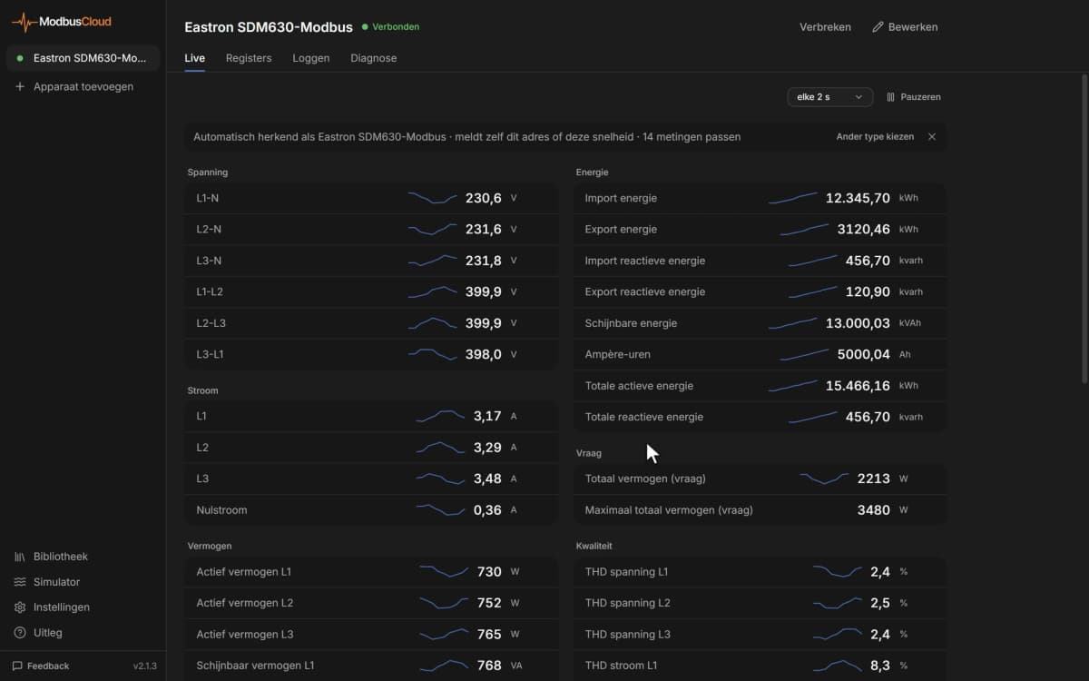
- Show output frequency, motor current and power of every pump or fan drive on one dashboard.
- Get an email when the latest fault code is not 0 or the unit temperature passes a limit.
- Keep a year of motor power and run hours to compare duty cycles between pumps.
- Change the PID set point or a preset speed remotely when the building needs another pressure or airflow.
- Start, stop and reset a drive with the control word after a fault has been checked on site.
Installation
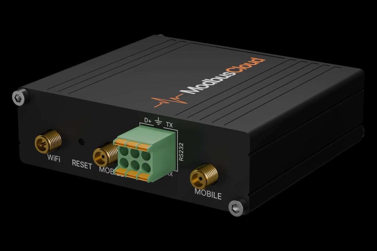
Wire RS485 A and B of the DG1 control board to the RS485 port of the ModbusCloud Gateway with twisted pair cable, and terminate both ends of the bus.
On the keypad set RS485 Comm Set (P20.3.1.1) to Modbus RTU, then slave address, baud rate and parity in menu P20.3.2. The defaults are address 1, 19200 baud, even parity.
In ModbusCloud add a Modbus device with the same address and serial settings and import this template.
Check that output frequency and DC-link voltage come in, then compare them with the keypad to confirm the scaling.
To control the drive over Modbus, set the control place and reference source to Fieldbus (P1.11 and P1.15).
Things to watch for
The drive does not answer on the RS485 bus. What should I check?
Check that P20.3.1.1 is set to Modbus RTU and not BACnet MS/TP, and that address, baud rate and parity in P20.3.2 match ModbusCloud. Swap A and B if nothing answers, and make sure the bus is terminated at both ends. Each drive needs its own address.
Why does output frequency read 5000 instead of 50 Hz?
The drive sends values as whole numbers without a decimal point. For monitor values the resolution is not in the register list, so compare the reading with the keypad and set the scale in ModbusCloud, for example 0.01 for a frequency shown with two decimals.
I write the speed reference but the motor does not start.
The drive only follows Modbus when the control place (P1.11) and the reference (P1.15) are set to Fieldbus. Then write the control word with bit 0 set to run. The speed reference runs from 0 to 10000 for 0 to 100 percent between minimum and maximum frequency.
A parameter does not change when I write it.
Several parameters, such as motor data, maximum frequency and application settings, only accept a new value when the drive is stopped. Read the parameter first, write the new value with the motor stopped, and read it back to confirm.
Is it safe to write parameters from ModbusCloud?
Writing changes how the motor runs. A wrong ramp, frequency limit or start command can start a pump or fan unexpectedly. Only write values you have verified for the installation, and agree on site who may start the drive remotely.


Want to see how it works?