









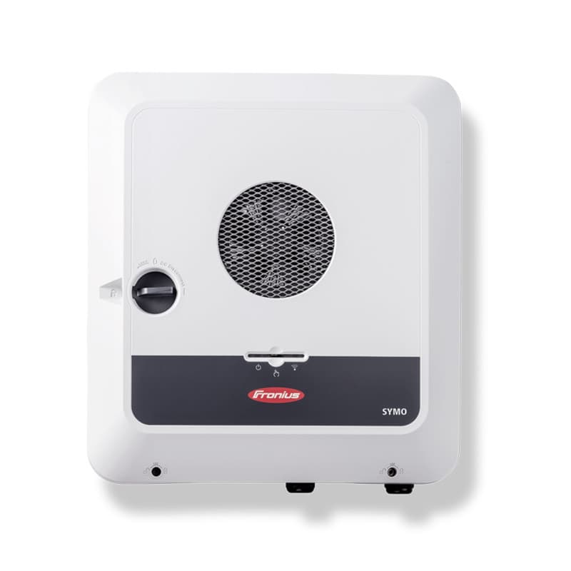
Fronius SnapInverter
Controls a Fronius SnapInverter via Modbus RTU over RS-485.
Template for the Fronius SnapInverter solar inverter using Modbus RTU over RS-485 at 9600 baud. It enables monitoring and control of the inverter through a ModbusCloud gateway connected to your cloud dashboard.
- Protocol
- Modbus RTU
- Connection
- RS485, 9600 baud
- Registers
- 0, read only
- Brand
- Fronius
- Compatible models
- Fronius SnapInverter
- Last updated
Send your device list
If a device is not in the library yet, we build the template for free as soon as we have the register data.
Use cases
- Monitor real-time AC power output and daily energy yield of a Fronius SnapInverter on a cloud dashboard.
- Create an alert when the inverter reports a fault code or goes offline unexpectedly.
- Track cumulative energy production across multiple Fronius SnapInverter sites from one platform.
- Compare DC input voltage and current to detect panel degradation or shading issues over time.
- Generate monthly energy production reports for your customer or for subsidy documentation.
Installation
Connect the ModbusCloud Gateway to the RS-485 terminal on the Fronius SnapInverter using a twisted-pair cable with correct A, B, and GND wiring.
Enable the Modbus RTU interface on the Fronius SnapInverter through the inverter setup menu or the Fronius web interface, and set the baud rate to 9600.
Assign a unique Modbus slave address on the inverter (for example, address 1) and note it for configuration in the template.
If the gateway is at the end of the RS-485 bus, enable the 120 ohm termination resistor on the gateway or add an external termination resistor.
Import the Fronius SnapInverter template in the ModbusCloud platform and set the slave address to match the inverter configuration.
Verify the connection by checking that live register values appear on the ModbusCloud dashboard after the first polling cycle.
Things to watch for
The gateway cannot communicate with the Fronius SnapInverter. What should I check?
Verify that Modbus RTU is enabled on the inverter and that the baud rate is set to 9600. Confirm the RS-485 wiring: A to A, B to B, and GND to GND. Also check that the slave address in the template matches the address configured on the inverter.
Do I need a termination resistor on the RS-485 bus?
Yes, if the ModbusCloud gateway or the inverter is at the end of the bus, a 120 ohm termination resistor should be placed across the A and B lines. Some gateways have a built-in termination resistor that can be enabled via a jumper or software setting.
Which Fronius SnapInverter models are compatible with this template?
This template targets the Fronius SnapInverter series. Specific register availability may vary depending on the model and firmware version. Check the Fronius Modbus register map documentation for your model to confirm supported data points.
Can I connect multiple Fronius SnapInverters on the same RS-485 bus?
Yes, you can daisy-chain multiple inverters on one RS-485 bus. Assign each inverter a unique Modbus slave address and add a separate template instance in ModbusCloud for each device.



Want to see how it works?
