








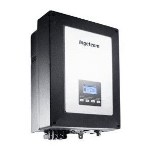
Ingeteam Ingecon 1Play TL M
Monitors and controls Ingeteam Ingecon 1Play TL M solar inverter via Modbus
This template connects to the Ingeteam Ingecon 1Play TL M solar inverter via Modbus RTU at 9600 baud. It reads AC and DC electrical parameters, energy totals, alarm codes, and self-consumption data. It also allows active power limitation and start/stop control of the inverter.
- Protocol
- Modbus RTU
- Connection
- RS485, 9600 baud
- Registers
- 30, read and write
- Brand
- Ingeteam
- Key readings
- Vac, Iac, Fac · Active/Reactive/Apparent Power · PV Voltage and Current (PV1, PV2) · Total and Daily Energy · Alarm Codes 1 to 4 · Self-Consumption Ratio
- Available commands
- Pac Limitation · Stop/Start
- Compatible models
- Ingecon 1 Play TL M
- Last updated
Registers (30)
28 read, 2 write
| Name | Unit | Access | Address (Hidden until you enter your email) | Function (hidden) | Type (hidden) |
|---|---|---|---|---|---|
| Vac | Volt x10 | Read | |||
| Iac | Amp x100 | Read | |||
| Total Energy | kWh | Read | |||
| Total Operation Hours | h | Read | |||
| Total Number of Connections | count | Read | |||
| Alarm Code 1 | Read | ||||
| Alarm Code 2 | Read | ||||
| Alarm Code 3 | Read | ||||
| Alarm Code 4 | Read | ||||
| Warming | Read | ||||
| Fac | Hertz x100 | Read | |||
| Apparent Power (S) | VA | Read | |||
| Reactive Power (Q) | var | Read | |||
| Active Power (P) | W | Read | |||
| CosPhi | x1000 | Read | |||
| Ipv 1 | Amp x100 | Read | |||
| Ipv 2 | Amp x100 | Read | |||
| Vpv 1 | Volt | Read | |||
| Vpv 2 | Volt | Read | |||
| Ppv | W | Read | |||
| Ppv 1 | W | Read | |||
| Ppv 2 | W | Read | |||
| Riso | kOhm | Read | |||
| Wattmeter (Self-Consumption) | W | Read | |||
| Power Reduction Rate | % | Read | |||
| Power Reduction Reason | Read | ||||
| Daily Energy | kWh x100 | Read | |||
| Self-Consumption Ratio | % | Read | |||
| Pac Limitation | Write | ||||
| Stop(5) - Start(6) | Write |
Loading registers…
Send your device list
If a device is not in the library yet, we build the template for free as soon as we have the register data.
Use cases
- Monitor real-time AC and DC voltages, currents, and power output on a live ModbusCloud dashboard.
- Track daily and total energy production to verify PV system performance over time.
- Create alerts when any of the four alarm code registers indicate a fault condition.
- Remotely limit active power output (Pac Limitation) for grid compliance or export restrictions.
- Use Start/Stop control to remotely shut down or restart the inverter without a site visit.
- Log self-consumption ratio data to help customers optimize their energy usage patterns.
Installation
Connect the ModbusCloud Gateway to the Ingeteam Ingecon 1Play TL M RS-485 port using a twisted-pair cable with correct A/B polarity and a common ground.
Set the inverter Modbus slave address via the inverter's front panel or configuration menu and ensure it matches the address configured in the ModbusCloud template.
Confirm the serial communication settings on the inverter are 9600 baud, 8 data bits, 1 stop bit, and no parity (or match the inverter's default parity setting).
Import the Ingeteam Ingecon 1Play TL M template in the ModbusCloud platform and assign it to the gateway's Modbus RTU channel.
Verify the register offset convention (0-based vs 1-based) used by your inverter firmware matches the template configuration, adjusting if necessary.
Check live data in the ModbusCloud dashboard to confirm correct scaling for Vac (x10), Iac (x100), Fac (x100), CosPhi (x1000), and Daily Energy (x100).
Things to watch for
I see values that are off by one register. What is wrong?
The Ingeteam documentation may use 0-based or 1-based register addressing. Compare the template register map with your inverter manual and apply a +1 or -1 offset if readings appear shifted.
Vac, Iac, or frequency values look unreasonably large or small. How do I fix this?
These registers use specific scaling factors. Vac must be divided by 10, Iac and Fac by 100, CosPhi by 1000, and Daily Energy by 100. Confirm the scaling is applied correctly in the template configuration.
The gateway cannot communicate with the inverter at all. What should I check?
Verify RS-485 wiring polarity (A to A, B to B), confirm the baud rate is set to 9600 on both the inverter and the gateway, and check that the Modbus slave address matches. Ensure proper bus termination if the cable run is long.
Total Energy or Daily Energy shows incorrect values. What could be the cause?
Total Energy is a uint32 register and Daily Energy is an int32 register. Make sure the template is reading both 16-bit words in the correct byte order. Check your inverter firmware documentation for the expected word order (big-endian or little-endian).
Want to see how it works?
