








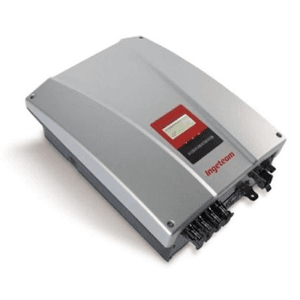
Ingeteam Ingecon Lite
Controls an Ingeteam 1-phase inverter via Modbus RTU.
Template for the Ingeteam Ingecon Lite 1-phase solar inverter via Modbus RTU. It reads AC and PV measurements, total energy, alarm codes, and operation hours. It also provides start/stop control and active power limitation.
- Protocol
- Modbus RTU
- Connection
- RS485, 9600 baud
- Registers
- 14, read and write
- Brand
- Ingeteam
- Key readings
- AC Voltage · AC Current · Active Power · PV Voltage and Current · Total Energy · Alarm Code
- Available commands
- Pac Limitation · Start/Stop
- Compatible models
- Ingecon Lite
- Last updated
Registers (14)
12 read, 2 write
| Name | Unit | Access | Address (Hidden until you enter your email) | Function (hidden) | Type (hidden) |
|---|---|---|---|---|---|
| Vac | Volt | Read | |||
| Iac | Amp x100 | Read | |||
| Total Energy | kWh | Read | |||
| Total Operation Hours | h | Read | |||
| Total Number of Connections | Read | ||||
| Alarm Code | Read | ||||
| Fac | Hertz x100 | Read | |||
| Active Power (P) | W | Read | |||
| CosPhi | x1000 | Read | |||
| Ipv | Amp x100 | Read | |||
| Vpv | Volt | Read | |||
| CosPhiSign | Read | ||||
| Pac Limitation | Write | ||||
| Start/Stop | Write |
Loading registers…
Send your device list
If a device is not in the library yet, we build the template for free as soon as we have the register data.
Use cases
- Monitor real-time PV voltage, current, and active power output on a live cloud dashboard for each installation.
- Track cumulative energy production and operation hours to generate monthly performance reports for customers.
- Create an alert when the inverter alarm code changes from zero, indicating a fault that requires on-site attention.
- Remotely start or stop the inverter during commissioning or scheduled maintenance without visiting the site.
- Apply active power limitation remotely to comply with grid operator curtailment requests or feed-in restrictions.
- Compare AC output power against DC input power to detect efficiency drops or shading issues over time.
Installation
Connect the Modbus RTU wiring (A, B, and GND) from the ModbusCloud Gateway to the RS-485 terminal on the Ingeteam Ingecon Lite inverter.
Set the baud rate on the gateway to 9600 to match the inverter default, and configure the correct Modbus slave address as set on the inverter.
Enable Modbus RTU communication on the Ingecon Lite inverter if it is not active by default, using the inverter front panel or configuration tool.
Add a 120 ohm termination resistor at the end of the RS-485 bus if the gateway or inverter is the last device on the line.
Import the Ingeteam Ingecon Lite template in the ModbusCloud platform and assign it to the gateway connection for this device.
Verify that AC voltage, PV voltage, and total energy readings appear correctly on the ModbusCloud dashboard before finalizing the installation.
Things to watch for
Why are my current readings 100 times too high?
The Ingecon Lite reports AC current and PV current with a x100 scaling factor. Ensure the template scaling is applied so that the raw register value is divided by 100 to display amperes correctly.
Total energy or total operation hours show incorrect values. What is wrong?
These values are unsigned 32-bit integers stored across two consecutive Modbus registers. Make sure your register configuration reads both registers as a uint32 pair rather than two separate 16-bit values.
The power factor value seems wrong or has the wrong sign. How do I fix it?
CosPhi is scaled by 1000 in the register. Additionally, a separate CosPhiSign register indicates whether the power factor is positive or negative (leading or lagging). Both registers must be read together to obtain an accurate power factor.
I cannot communicate with the inverter over Modbus RTU. What should I check?
Confirm that the baud rate is set to 9600 on both the gateway and the inverter. Verify the slave address matches, check the A and B wiring polarity, and ensure Modbus communication is enabled in the inverter settings.
Want to see how it works?
