




INVT GD20
Frequency inverter that reports frequency, current, voltage and faults, with run and speed control.
The INVT GD20 is a compact frequency inverter that controls the speed of pumps, fans and conveyors in buildings and light industry. This Modbus RTU template reads frequency, current, voltage, power, status and fault code, and lets you start, stop and set the speed from ModbusCloud.
- Protocol
- Modbus RTU
- Connection
- RS485, 19200 baud
- Registers
- 41, read and write
- Brand
- INVT
- Key readings
- Output frequency · Output current · Output voltage · Bus voltage · Output power · Motor speed · Fault code
- Available commands
- Run and stop command · Frequency setpoint · PID reference · Torque setpoint · Frequency and torque limits
- Compatible models
- Goodrive20 (GD20)
- Last updated
Registers (41)
41 read, 15 write
| Name | Unit | Access | Address (Hidden until you enter your email) | Function (hidden) | Type (hidden) |
|---|---|---|---|---|---|
| Operating Frequency | Hz | Read | 12288 | FC03 | uint16 |
| Set Frequency | Hz | Read | 12289 | FC03 | uint16 |
| Output Current | A | Read | 12292 | FC03 | uint16 |
| Output Voltage | V | Read | 12291 | FC03 | uint16 |
| Bus Voltage | V | Read | 12290 | FC03 | uint16 |
| Output Power | % | Read | |||
| Output Torque | % | Read | |||
| Operation Speed | rpm | Read | |||
| PID Setting | % | Read | |||
| PID Feedback | % | Read | |||
| Torque Setting | % | Read | |||
| AI1 Voltage | V | Read | |||
| AI2 Voltage | V | Read | |||
| AI3 Voltage | V | Read | |||
| Pulse Input Frequency | Read | ||||
| Input State | Read | ||||
| Output State | Read | ||||
| Multi-Step Speed Step | Read | ||||
| External Length | Read | ||||
| External Count | Read | ||||
| Status Word 1 | Read | ||||
| Status Word 2 | Read | ||||
| Fault Code | Read | ||||
| Fault Code 5000H | Read | ||||
| Device Identification | Read | ||||
| VFD Identification Code | Read | ||||
| Control Command | Read and write | ||||
| Communication Frequency Setpoint | Hz | Read and write | |||
| PID Reference | % | Read and write | |||
| PID Feedback Value | % | Read and write | |||
| Torque Setpoint | % | Read and write | |||
| Forward Upper Frequency Limit | Hz | Read and write | |||
| Reverse Upper Frequency Limit | Hz | Read and write | |||
| Motoring Torque Limit | % | Read and write | |||
| Braking Torque Limit | % | Read and write | |||
| Special Control Word | Read and write | ||||
| Virtual Input Command | Read and write | ||||
| Virtual Output Command | Read and write | ||||
| VF Separation Voltage Setpoint | % | Read and write | |||
| AO1 Output Setting | % | Read and write | |||
| AO2 Output Setting | % | Read and write |
Loading registers…
Send your device list
If a device is not in the library yet, we build the template for free as soon as we have the register data.
Use cases
- Show frequency, current and power of every drive in a pump or fan installation on one dashboard.
- Get an email alert when the fault code is not 0 or the status word reports a fault.
- Keep a year of current and power history to see how a pump load changes over the seasons.
- Change the frequency setpoint from ModbusCloud to adjust a fan without visiting the site.
- Track the PID setpoint and feedback to check that a pressure or flow loop holds its target.
Installation
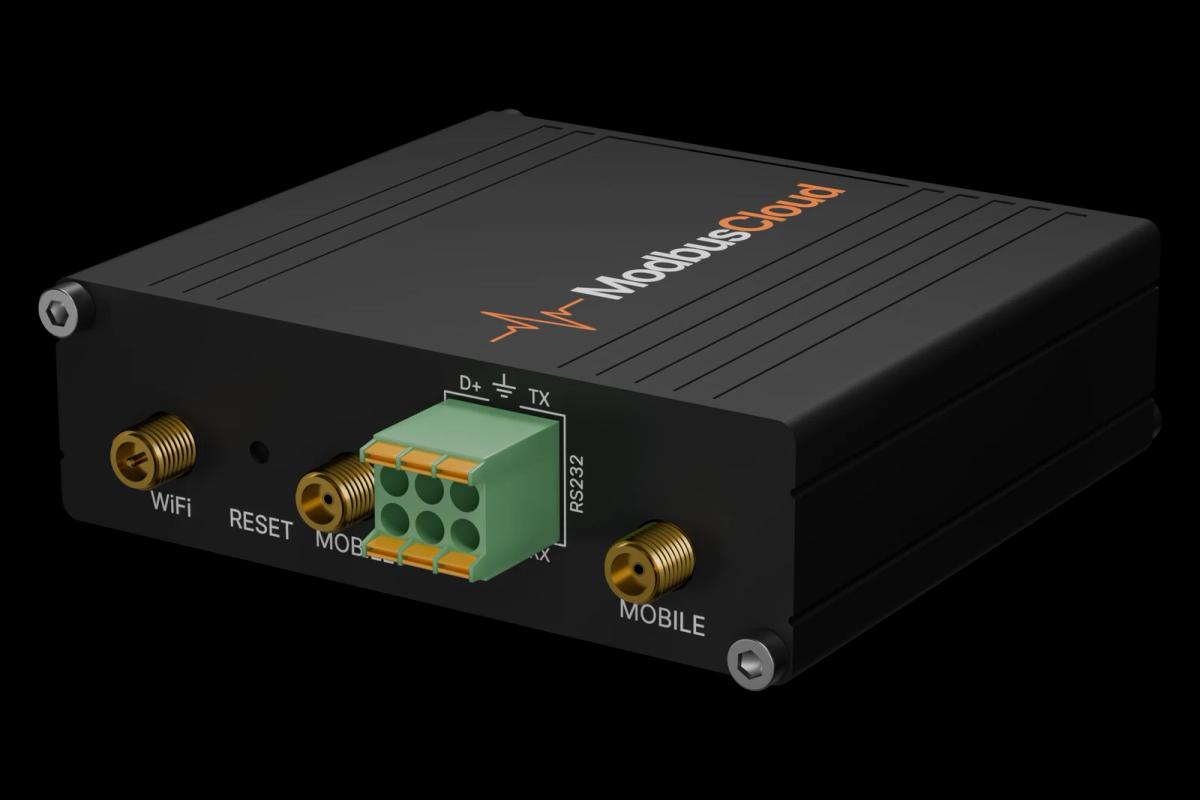
Connect RS485 A and B of the ModbusCloud Gateway to the 485 plus and minus terminals of the drive and fit the termination jumper at the end of the bus.
Set P14.00 (address), P14.01 (baud rate) and P14.02 (data format) on the keypad; the defaults are address 1, 19200 baud, 8E1.
In ModbusCloud, add a Modbus RTU device with the same address and settings, and import this template.
Check that Operating Frequency, Bus Voltage and Status Word 1 come in; start the motor to see frequency and current change.
To control the drive over Modbus, set P00.01 to 2 and select Modbus as the frequency source before writing commands.
Things to watch for
The drive does not answer on the bus. What should I check?
Check P14.00 to P14.02 against the device settings in ModbusCloud: address, baud rate and parity must match, the default is 19200 baud 8E1. Swap plus and minus if nothing answers, and fit the termination jumper on the drive at the end of the bus.
Writing the run command or frequency has no effect. Why?
The drive only accepts commands from Modbus when P00.01 is set to 2 (communication run command channel) and the frequency source is set to Modbus. For the PID reference, P09.00 must also select Modbus.
What should I know before writing to the drive?
A run command starts the motor directly, so make sure the machine is safe to run. Write one command at a time and read Status Word 1 to confirm the result. The frequency setpoint is in 0.01 Hz steps and stays within the frequency limits set in P00.
A write is refused with an error code. What does it mean?
Code 07H means the parameter is read-only, 08H that it cannot be changed while the drive runs, and 09H that a user password locks the drive. Stop the drive or enter the password first. Code 04H means the value is not allowed, for example a terminal function that is already in use.




Want to see how it works?