
LS Electric G100
Compact frequency inverter for pumps, fans and conveyors with speed, current, energy and trip data.
The LS Electric G100 is a compact frequency inverter that controls the speed of pumps, fans and conveyors from 0.4 to 22 kW. This Modbus RTU template reads current, frequency, power, temperature, energy, run time and trip information, and lets you start, stop and set the speed, ramps and PID values from ModbusCloud.
- Protocol
- Modbus RTU
- Connection
- RS485, 9600 baud
- Registers
- 111, read and write
- Brand
- LS Electric
- Key readings
- Output current · Output frequency · Output power · DC link voltage · Module temperature · Energy consumption · Operation state · Trip information
- Available commands
- Run and stop command · Frequency reference · Acceleration and deceleration time · PID reference · Torque limits
- Compatible models
- LSLV-G100 (0.4 to 22 kW) · LS Electric LSLV-G100 frequency inverter
- Last updated
Registers (111)
111 read, 40 write
| Name | Unit | Access | Address (Hidden until you enter your email) | Function (hidden) | Type (hidden) |
|---|---|---|---|---|---|
| Output Current | A | Read | 783 | FC03 | uint16 |
| Output Frequency | Hz | Read | 784 | FC03 | uint16 |
| Output Speed | rpm | Read | 785 | FC03 | uint16 |
| Motor Feedback Speed | rpm | Read | 786 | FC03 | int16 |
| Output Voltage | V | Read | 787 | FC03 | uint16 |
| DC Link Voltage | V | Read | |||
| Output Power | kW | Read | |||
| Output Torque | % | Read | |||
| PID Reference | % | Read | |||
| PID Feedback | % | Read | |||
| Inverter Module Temperature | °C | Read | |||
| Power Consumption kWh | kWh | Read | |||
| Power Consumption MWh | MWh | Read | |||
| Analog Input V1 | % | Read | |||
| Analog Input V0 | % | Read | |||
| Analog Input I2 | % | Read | |||
| Analog Output 1 | % | Read | |||
| Analog Output 2 | % | Read | |||
| Inverter Operation State | Read | ||||
| Command Source | Read | ||||
| Latch Trip Information 1 | Read | ||||
| Latch Trip Information 2 | Read | ||||
| Level Trip Information | Read | ||||
| Hardware Diagnosis Trip Information | Read | ||||
| Warning Information | Read | ||||
| Latch Trip Information 3 | Read | ||||
| Digital Input Status | Read | ||||
| Digital Output Status | Read | ||||
| Virtual Digital Input Status | Read | ||||
| Frequency Command | Hz | Read and write | |||
| Speed Command | rpm | Read and write | |||
| Operation Command | Read and write | ||||
| Acceleration Time | s | Read and write | |||
| Deceleration Time | s | Read and write | |||
| Virtual Digital Input Control | Read and write | ||||
| Digital Output Control | Read and write | ||||
| PID Reference Command | % | Read and write | |||
| PID Feedback Command | % | Read and write | |||
| Motor Rated Current | A | Read and write | |||
| Motor Rated Voltage | V | Read and write | |||
| Torque Reference | % | Read and write | |||
| Forward Motoring Torque Limit | % | Read and write | |||
| Forward Regeneration Torque Limit | % | Read and write | |||
| Reverse Motoring Torque Limit | % | Read and write | |||
| Reverse Regeneration Torque Limit | % | Read and write | |||
| Torque Bias | % | Read and write | |||
| Save Parameters | Read and write | ||||
| Monitor Mode Initialization | Read and write | ||||
| Parameter Initialization | Read and write | ||||
| Changed Parameter Display | Read and write | ||||
| Delete All Fault History | Read and write | ||||
| Delete User Registered Codes | Read and write | ||||
| Hide Parameter Mode | Read and write | ||||
| Lock Parameter Mode | Read and write | ||||
| Initialize Power Consumption | Read and write | ||||
| Initialize Operation Time | Read and write | ||||
| Initialize Fan Time | Read and write | ||||
| On Time Days | d | Read | |||
| On Time Minutes | min | Read | |||
| Run Time Days | d | Read | |||
| Run Time Minutes | min | Read | |||
| Fan Time Days | d | Read | |||
| Fan Time Minutes | min | Read | |||
| Inverter Model | Read | ||||
| Inverter Capacity | Read | ||||
| Input Voltage and Cooling | Read | ||||
| Software Version | Read | ||||
| Motor 1 Poles | Read | ||||
| Motor 2 Poles | Read | ||||
| Selected Motor Poles | Read | ||||
| Hz Rpm Selection | Read | ||||
| Selected Motor | Read | ||||
| Option Card | Read | ||||
| Inverter Capacity (Compatible Area) | Read | ||||
| Input Voltage Class (Compatible Area) | Read | ||||
| Software Version (Compatible Area) | Read | ||||
| Target Frequency (Compatible Area) | Hz | Read and write | |||
| Operation Command (Compatible Area) | Read and write | ||||
| Acceleration Time (Compatible Area) | s | Read and write | |||
| Deceleration Time (Compatible Area) | s | Read and write | |||
| Output Current (Compatible Area) | A | Read | |||
| Output Frequency (Compatible Area) | Hz | Read | |||
| Output Voltage (Compatible Area) | V | Read | |||
| DC Link Voltage (Compatible Area) | V | Read | |||
| Output Power (Compatible Area) | kW | Read | |||
| Operation Status (Compatible Area) | Read | ||||
| Fault Trip Information (Compatible Area) | Read | ||||
| Input Terminal Information (Compatible Area) | Read | ||||
| Output Terminal Information (Compatible Area) | Read | ||||
| V1 Input (Compatible Area) | % | Read | |||
| V0 Input (Compatible Area) | % | Read | |||
| I2 Input (Compatible Area) | % | Read | |||
| Motor Speed (Compatible Area) | rpm | Read | |||
| Hz Rpm Selection (Compatible Area) | Read | ||||
| Selected Motor Poles (Compatible Area) | Read | ||||
| Status Parameter 1 | Read | ||||
| Status Parameter 2 | Read | ||||
| Status Parameter 3 | Read | ||||
| Status Parameter 4 | Read | ||||
| Status Parameter 5 | Read | ||||
| Status Parameter 6 | Read | ||||
| Status Parameter 7 | Read | ||||
| Status Parameter 8 | Read | ||||
| Control Parameter 1 | Read and write | ||||
| Control Parameter 2 | Read and write | ||||
| Control Parameter 3 | Read and write | ||||
| Control Parameter 4 | Read and write | ||||
| Control Parameter 5 | Read and write | ||||
| Control Parameter 6 | Read and write | ||||
| Control Parameter 7 | Read and write | ||||
| Control Parameter 8 | Read and write |
Loading registers…
Send your device list
If a device is not in the library yet, we build the template for free as soon as we have the register data.
Use cases
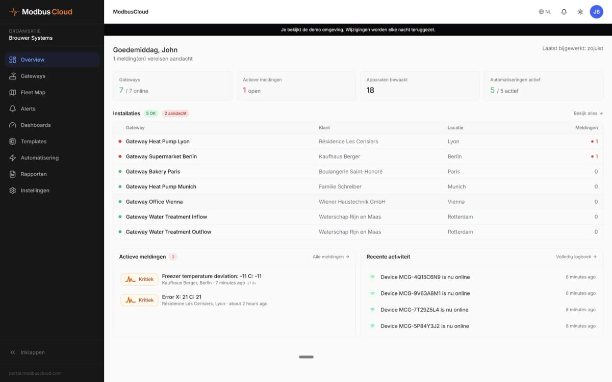
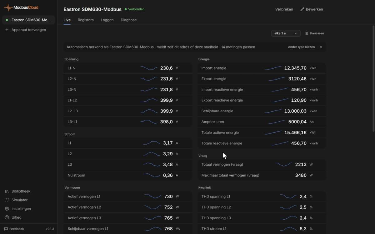
- Show output frequency, current and power of every drive on one ModbusCloud dashboard.
- Get an email when a trip bit is set or the module temperature passes your own limit.
- Track energy consumption and run time per drive in the history for maintenance planning.
- Change the frequency reference of a pump or fan remotely without going to the cabinet.
- Reset a trip from the portal after you have checked the cause.
- Compare the PID reference with the feedback to see whether a pressure or flow loop keeps up.
Installation
Connect S+ and S- of the G100 to RS485 A and B of the ModbusCloud Gateway with a shielded twisted pair, and terminate both ends of the bus.
Set CM.01 to a unique station ID, CM.02 to Modbus RTU, and CM.03 and CM.04 to the speed and frame used on the bus.
If ModbusCloud should run the drive, set drv to 3 and Frq to 6 (Int 485) in the operation group.
In ModbusCloud, add a Modbus device (RTU) with the same ID and settings, and import this template.
Check that Output Frequency and DC Link Voltage show plausible values.
Things to watch for
The G100 does not answer. What should I check?
Check that CM.02 is Modbus RTU and not LS INV 485, that the station ID, speed and frame (CM.01, CM.03, CM.04) match the device in ModbusCloud, and swap S+ and S- if needed. Use only one of the two RS485 connections, the terminal block or the RJ45 port.
Why do all values look shifted by one register?
The G100 uses its listed communication address minus one in the Modbus message, and this template already does that. If you add registers yourself from the G100 tables, subtract one from the listed address as well.
The drive ignores my run or frequency command.
The drive only accepts commands over RS485 when drv is set to 3 (Int 485) and Frq to 6 (Int 485). Write 3 to Operation Command to run forward, 1 to run in reverse and 0 to stop.
What should I know before writing settings?
A run command starts the motor, so make sure the machine is safe to start. Values written over communication are lost after a power cycle unless you write 0 and then 1 to Save Parameters. A frequency reference written to Frequency Command is never saved.




Want to see how it works?