








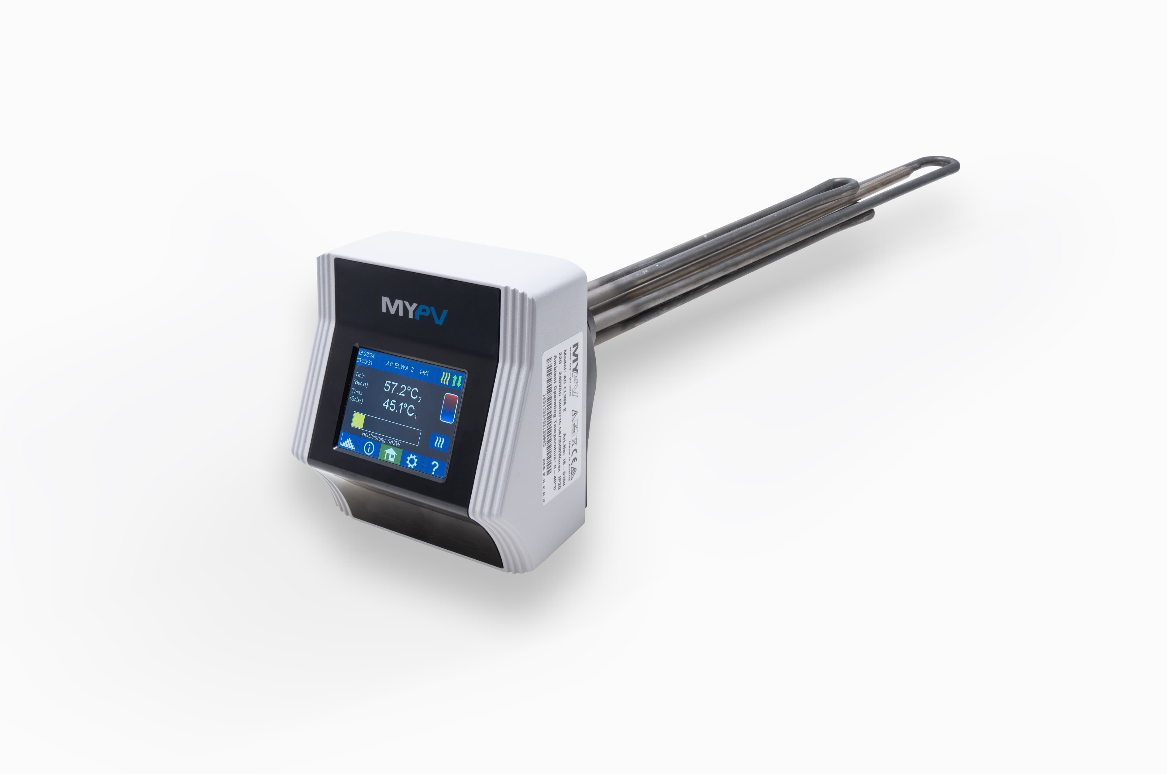
my-PV AC ELWA 2
Controls PV surplus power for hot water heating via Modbus TCP
Template for the my-PV AC ELWA 2 electric hot water heater connected via Modbus TCP. It reads temperatures, power consumption, device state, and operation mode, and allows setting target temperature, power level, and timeout remotely through the ModbusCloud platform.
- Protocol
- Modbus TCP
- Connection
- Ethernet, Modbus TCP
- Registers
- 7, read and write
- Brand
- my-PV
- Key readings
- Power · Temperature T1 · Temperature T2 · Target Temperature · Device State · Operation Mode
- Available commands
- Target Temperature · Power · Operation Mode · Power Timeout
- Compatible models
- AC ELWA 2
- Last updated
Registers (7)
6 read, 5 write
| Name | Unit | Access | Address (Hidden until you enter your email) | Function (hidden) | Type (hidden) |
|---|---|---|---|---|---|
| Read Target Temperatur | °C | Read and write | |||
| Read Temperatur T1 | °C | Read | |||
| Read Power | W | Read and write | |||
| Read Temperatur T2 | °C | Read | |||
| Read Device State | Read and write | ||||
| Read Operation Mode | Read and write | ||||
| Set Power Timeout | s | Write |
Loading registers…
Send your device list
If a device is not in the library yet, we build the template for free as soon as we have the register data.
Use cases
- Monitor real-time heating power and tank temperatures on a live dashboard for your customer.
- Set the target water temperature remotely based on seasonal or occupancy requirements.
- Create an alert when tank temperature T1 drops below a defined minimum for more than 15 minutes.
- Adjust power setpoint dynamically to match available PV surplus reported by a connected inverter.
- Log daily energy usage for hot water heating and generate monthly reports for the building owner.
- Verify device state and operation mode remotely to reduce unnecessary service visits.
Installation
On the AC ELWA 2 display, set the control type to Modbus TCP and configure the control timeout to 60 seconds as described in the my-PV operation manual.
Connect the AC ELWA 2 to the same local network as the ModbusCloud Gateway using an Ethernet cable or a reliable Wi-Fi bridge.
Note the IP address assigned to the AC ELWA 2 and verify you can reach it from the gateway network segment.
In the ModbusCloud portal, add a new Modbus TCP device and enter the IP address and default Modbus TCP port of the AC ELWA 2.
Import the my-PV AC ELWA 2 template from the ModbusCloud template library and assign it to the device.
Confirm that readings such as Power, Temperature T1, and Device State appear correctly on the dashboard before handing the system over to the customer.
Things to watch for
The gateway cannot connect to the AC ELWA 2 over Modbus TCP. What should I check?
Verify that Modbus TCP is selected as the control type on the AC ELWA 2 display. Confirm the device IP address is correct and that the gateway and the AC ELWA 2 are on the same network subnet. Check that no firewall is blocking the Modbus TCP port.
Readings appear briefly but then the device stops responding. Why?
The AC ELWA 2 has a 60-second control timeout. If no Modbus write command is sent within that window, the device may revert to standalone mode. Ensure the ModbusCloud polling interval is shorter than 60 seconds so the connection stays active.
Temperature values seem incorrect or show zero. What could be wrong?
Check that the temperature sensors T1 and T2 are properly connected to the AC ELWA 2. If only one sensor is installed, the unused channel may report zero. Consult the my-PV manual for sensor wiring details.
Can I control both target temperature and power at the same time?
Yes. The template exposes separate registers for target temperature and power setpoint. You can write to both, but the AC ELWA 2 will respect its internal safety limits. Always verify behaviour after changing settings.

Want to see how it works?
