








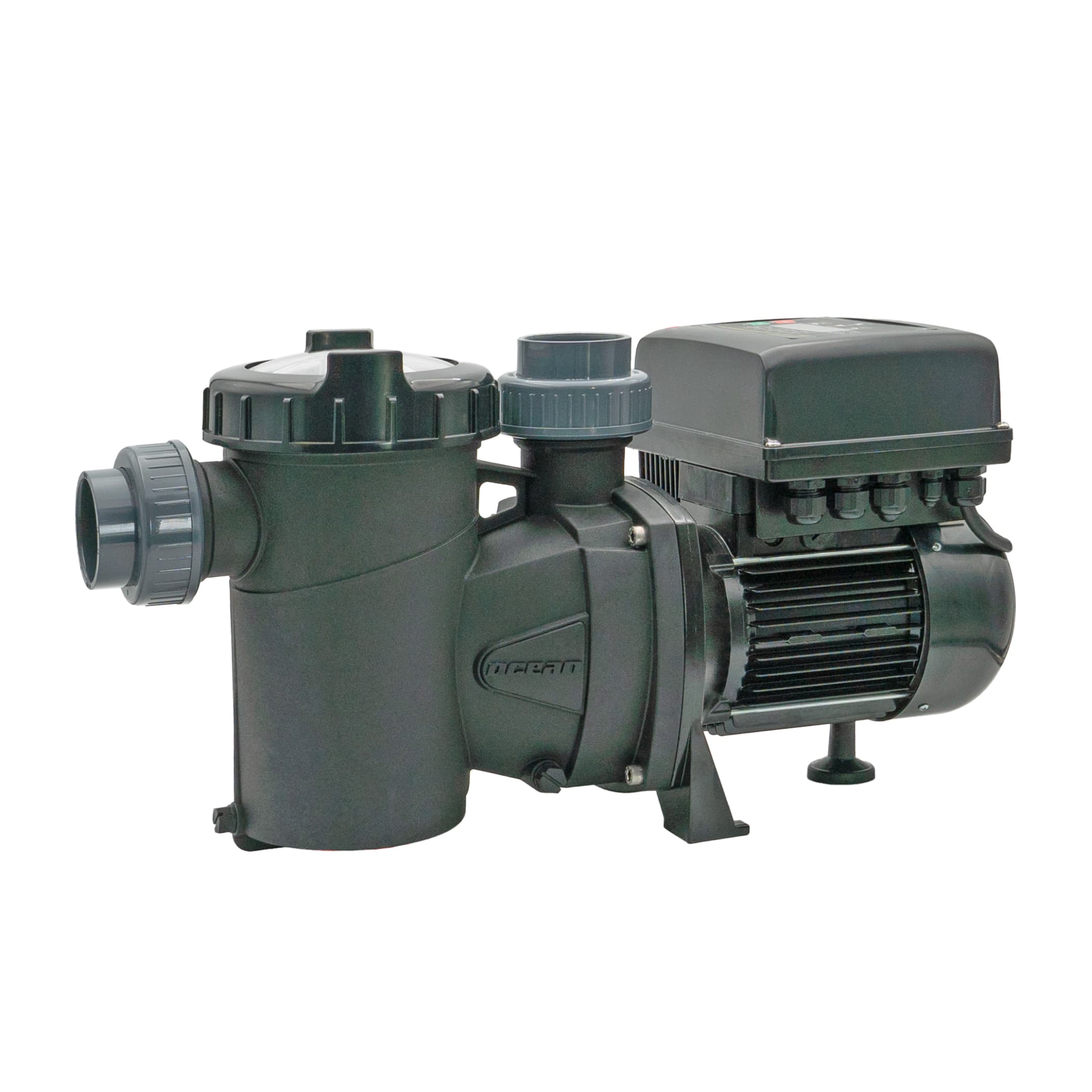
Ocean Poolpump Inver iQ 300
Controls a variable-speed pool pump via Modbus RTU for energy-efficient filtration
Peraqua Ocean Poolpump Inver iQ 300 template for Modbus RTU. Reads flow rate, water pressure, motor power, energy consumption, and alarm counters. Allows setting the volume flow rate for filter time programs via a writable register.
- Protocol
- Modbus RTU
- Connection
- RS485, 9600 baud
- Registers
- 23, read and write
- Brand
- Peraqua
- Key readings
- Flowrate · Water pressure · Actual motor power · Energy counter (MSB/LSB) · Alarm counters (F01 to X13) · Digital input 1 status
- Available commands
- Flowrate time program 1
- Compatible models
- Ocean Poolpump Inver iQ 300
- Last updated
Registers (23)
23 read, 1 write
| Name | Unit | Access | Address (Hidden until you enter your email) | Function (hidden) | Type (hidden) |
|---|---|---|---|---|---|
| FLOWRATE | m³/h | Read | |||
| WATER PRESSURE | Bar | Read | |||
| ACTUAL MOTOR POWER | kW | Read | |||
| ENERGY COUNTER (MSB) | Read | ||||
| ENERGY COUNTER (LSB) | Read | ||||
| ALARM F08 COUNTER | count | Read | |||
| ALARM F01 COUNTER | count | Read | |||
| ALARM F02 COUNTER | count | Read | |||
| ALARM F03 COUNTER | count | Read | |||
| ALARM F04 COUNTER | count | Read | |||
| ALARM F05 COUNTER | count | Read | |||
| ALARM F06 COUNTER | count | Read | |||
| ALARM F07 COUNTER | count | Read | |||
| ALARM A09 COUNTER | count | Read | |||
| ALARM A10 COUNTER | count | Read | |||
| ALARM A11 COUNTER | count | Read | |||
| ALARM A12 COUNTER | count | Read | |||
| ALARM X13 COUNTER | count | Read | |||
| TIME PROGRAM 1 | Read | ||||
| START TIME PROGRAM 1 | Read | ||||
| END TIME PROGRAM 1 | Read | ||||
| DIGITAL INPUT 1 | Read | ||||
| FLOWRATE TIME PROGRAM 1 | V | Read and write |
Loading registers…
Send your device list
If a device is not in the library yet, we build the template for free as soon as we have the register data.
Use cases
- Monitor actual flow rate and water pressure on a live dashboard to verify filtration performance.
- Create an alert when an alarm counter increments so you can respond to pump faults before the customer notices.
- Adjust the volume flow setpoint remotely to increase flow during backwash cycles without visiting the site.
- Track cumulative energy consumption over time to demonstrate savings compared to a fixed-speed pump.
- Verify digital input 1 status remotely to confirm the pump is receiving a valid start signal from the safety circuit.
- Log motor power data to identify unusual load patterns that may indicate a clogged filter or blocked impeller.
Installation
Wire the Modbus RTU bus (A, B, GND) from the ModbusCloud Gateway to the RS-485 terminals on the Inver iQ 300 control unit, observing correct polarity.
If the control unit is mounted remotely from the pump motor, use a minimum cable cross-section of 4 x 2.5 mm2 and keep the distance under 30 metres.
On the pump display, set menu 15.2 MODBUS ADDRESS to 2, menu 15.4 MODBUS PARITY to 2, and configure time program 1 to EXTERNAL with a 00:00 to 23:59 time range.
Ensure digital input IN1 is wired to your safety or automation relay so the pump can be started and stopped independently of Modbus.
In the ModbusCloud portal, import the Peraqua Ocean Inver iQ 300 template, set the gateway serial port to 9600 baud, 1 stop bit, no parity, and assign slave address 2.
Confirm live readings for flow rate, pressure, and motor power appear on the dashboard before putting the system into service.
Things to watch for
Why can I read values but not start or stop the pump via Modbus?
This is by design. The Inver iQ 300 requires a hardwired signal on digital input IN1 to start and stop. Modbus is limited to setting the volume flow setpoint and reading operational data.
The energy counter value looks wrong or too low. What is happening?
The energy counter is split across two 16-bit registers (MSB at address 54, LSB at address 55). Make sure both registers are read and combined correctly. The template handles this automatically, but verify that both register readings are non-zero.
I cannot establish Modbus communication with the pump. What should I check?
Confirm the pump menu settings: address 2, parity set to 2 (None). On the gateway, use 9600 baud, 1 stop bit, no parity. Check RS-485 wiring polarity (A to A, B to B) and ensure a termination resistor is present if the cable run is long.
Do I need to set volume and pressure units on the pump?
Yes. Set menu 1.3 VOLUME UNIT to m3 and menu 1.4 PRESSURE UNIT to bar so that register values match the scaling used in the template.
Want to see how it works?
