


Omron 3G3MX2
Frequency inverter for motors up to 15 kW: speed, current, power, faults and all drive settings.
The Omron 3G3MX2 is a compact frequency inverter that controls the speed of pumps, fans, conveyors and machines up to 15 kW. This Modbus RTU template reads frequency, current, voltage, power, temperatures and the fault history, and lets you start, stop and set the speed and every drive parameter from ModbusCloud.
- Protocol
- Modbus RTU
- Connection
- RS485, 9600 baud
- Registers
- 736, read and write
- Brand
- Omron
- Key readings
- Output frequency · Output current · Output voltage · Input power · DC bus voltage · Heat sink temperature · Trip factor · Run hours
- Available commands
- Run and stop · Rotation direction · Frequency setpoint · Acceleration and deceleration time · Trip reset
- Compatible models
- 3G3MX2 (MX2) 200 V single-phase 0.1 to 2.2 kW · 3G3MX2 (MX2) 200 V three-phase 0.1 to 15 kW · 3G3MX2 (MX2) 400 V three-phase 0.4 to 15 kW
- Last updated
Registers (736)
734 read, 573 write
| Name | Unit | Access | Address (Hidden until you enter your email) | Function (hidden) | Type (hidden) |
|---|---|---|---|---|---|
| Output Frequency Monitor | Hz | Read | |||
| Output Current Monitor | A | Read | |||
| Rotation Direction Monitor | Read | ||||
| PID Feedback Value Monitor | Read | ||||
| Multi-function Input Monitor | Read | ||||
| Multi-function Output Monitor | Read | ||||
| Output Frequency Monitor (After Conversion) | Read | ||||
| Real Frequency Monitor | Hz | Read | |||
| Torque Reference Monitor | % | Read | |||
| Torque Bias Monitor | % | Read | |||
| Output Torque Monitor | % | Read | |||
| Output Voltage Monitor | V | Read | |||
| Input Power Monitor | kW | Read | |||
| Integrated Power Monitor | Read | ||||
| Total RUN Time | h | Read | |||
| Power ON Time Monitor | h | Read | |||
| Fin Temperature Monitor | °C | Read | |||
| Life Assessment Monitor | Read | ||||
| Program Counter | Read | ||||
| Program Number | Read | ||||
| DC Voltage Monitor | V | Read | |||
| Regenerative Braking Load Rate Monitor | % | Read | |||
| Electronic Thermal Monitor | % | Read | |||
| Drive Programming Monitor (UM0) | Read | ||||
| Drive Programming Monitor (UM1) | Read | ||||
| Drive Programming Monitor (UM2) | Read | ||||
| Position Command Monitor | Read | ||||
| Current Position Monitor | Read | ||||
| Inverter Mode | Read | ||||
| Frequency Source Monitor | Read | ||||
| Run Source Monitor | Read | ||||
| Analog Input O Monitor | Read | ||||
| Analog Input OI Monitor | Read | ||||
| Pulse Train Input Monitor | % | Read | |||
| PID Deviation Monitor | % | Read | |||
| PID Output Monitor | % | Read | |||
| Output Frequency Setting | Hz | Read and write | |||
| Inverter Status A | Read | ||||
| Inverter Status B | Read | ||||
| Inverter Status C | Read | ||||
| PID Feedback | % | Read and write | |||
| Fault Count Monitor | Read | ||||
| Fault Monitor 1 Factor | Read | ||||
| Fault Monitor 1 Inverter Status | Read | ||||
| Fault Monitor 1 Frequency | Hz | Read | |||
| Fault Monitor 1 Current | A | Read | |||
| Fault Monitor 1 Voltage | V | Read | |||
| Fault Monitor 1 Running Time | h | Read | |||
| Fault Monitor 1 Power-on Time | h | Read | |||
| Fault Monitor 2 Factor | Read | ||||
| Fault Monitor 2 Inverter Status | Read | ||||
| Fault Monitor 2 Frequency | Hz | Read | |||
| Fault Monitor 2 Current | A | Read | |||
| Fault Monitor 2 Voltage | V | Read | |||
| Fault Monitor 2 Running Time | h | Read | |||
| Fault Monitor 2 Power-on Time | h | Read | |||
| Fault Monitor 3 Factor | Read | ||||
| Fault Monitor 3 Inverter Status | Read | ||||
| Fault Monitor 3 Frequency | Hz | Read | |||
| Fault Monitor 3 Current | A | Read | |||
| Fault Monitor 3 Voltage | V | Read | |||
| Fault Monitor 3 Running Time | h | Read | |||
| Fault Monitor 3 Power-on Time | h | Read | |||
| Fault Monitor 4 Factor | Read | ||||
| Fault Monitor 4 Inverter Status | Read | ||||
| Fault Monitor 4 Frequency | Hz | Read | |||
| Fault Monitor 4 Current | A | Read | |||
| Fault Monitor 4 Voltage | V | Read | |||
| Fault Monitor 4 Running Time | h | Read | |||
| Fault Monitor 4 Power-on Time | h | Read | |||
| Fault Monitor 5 Factor | Read | ||||
| Fault Monitor 5 Inverter Status | Read | ||||
| Fault Monitor 5 Frequency | Hz | Read | |||
| Fault Monitor 5 Current | A | Read | |||
| Fault Monitor 5 Voltage | V | Read | |||
| Fault Monitor 5 Running Time | h | Read | |||
| Fault Monitor 5 Power-on Time | h | Read | |||
| Fault Monitor 6 Factor | Read | ||||
| Fault Monitor 6 Inverter Status | Read | ||||
| Fault Monitor 6 Frequency | Hz | Read | |||
| Fault Monitor 6 Current | A | Read | |||
| Fault Monitor 6 Voltage | V | Read | |||
| Fault Monitor 6 Running Time | h | Read | |||
| Fault Monitor 6 Power-on Time | h | Read | |||
| Warning Monitor | Read | ||||
| Coil Operation Command | Read and write | ||||
| Coil Rotation Direction Command | Read and write | ||||
| Coil External Trip (EXT) | Read and write | ||||
| Coil Trip Reset (RS) | Read and write | ||||
| Coil Intelligent Input Terminal [1] | Read and write | ||||
| Coil Intelligent Input Terminal [2] | Read and write | ||||
| Coil Intelligent Input Terminal [3] | Read and write | ||||
| Coil Intelligent Input Terminal [4] | Read and write | ||||
| Coil Intelligent Input Terminal [5] | Read and write | ||||
| Coil Intelligent Input Terminal [6] | Read and write | ||||
| Coil Intelligent Input Terminal [7] | Read and write | ||||
| Coil Operation Status | Read | ||||
| Coil Rotation Direction | Read | ||||
| Coil Inverter Ready | Read | ||||
| Coil RUN (Running) | Read | ||||
| Coil FA1 (Constant-speed Reached) | Read | ||||
| Coil FA2 (Set Frequency Overreached) | Read | ||||
| Coil OL (Overload Advance Notice (1)) | Read | ||||
| Coil OD (Output Deviation for PID Control) | Read | ||||
| Coil AL (Alarm Signal) | Read | ||||
| Coil FA3 (Set Frequency Reached) | Read | ||||
| Coil OTQ (Over-torque) | Read | ||||
| Coil UV (Undervoltage) | Read | ||||
| Coil TRQ (Torque Limited) | Read | ||||
| Coil RNT (Operation Time Over) | Read | ||||
| Coil ONT (Plug-in Time Over) | Read | ||||
| Coil THM (Thermal Alarm Signal) | Read | ||||
| Coil BRK (Brake Release) | Read | ||||
| Coil BER (Brake Error) | Read | ||||
| Coil ZS (0 Hz Detection Signal) | Read | ||||
| Coil DSE (Speed Deviation Maximum) | Read | ||||
| Coil POK (Positioning Completed) | Read | ||||
| Coil FA4 (Set Frequency Overreached 2) | Read | ||||
| Coil FA5 (Set Frequency Reached 2) | Read | ||||
| Coil OL2 (Overload Notice Advance (2)) | Read | ||||
| Coil Odc: Analog O Disconnection Detection | Read | ||||
| Coil OIDc: Analog OI Disconnection Detection | Read | ||||
| Coil FBV (PID Feedback Comparison) | Read | ||||
| Coil NDc (Communication Train Disconnection) | Read | ||||
| Coil LOG1 (Logical Operation Result 1) | Read | ||||
| Coil LOG2 (Logical Operation Result 2) | Read | ||||
| Coil LOG3 (Logical Operation Result 3) | Read | ||||
| Coil WAC (Capacitor Life Warning) | Read | ||||
| Coil WAF (Cooling-fan Speed Drop) | Read | ||||
| Coil FR (Starting Contact Signal) | Read | ||||
| Coil OHF (Heat Sink Overheat Warning) | Read | ||||
| Coil LOC (Low-current Indication Signal) | Read | ||||
| Coil M01 (General Output 1) | Read | ||||
| Coil M02 (General Output 2) | Read | ||||
| Coil M03 (General Output 3) | Read | ||||
| Coil IRDY (Inverter Ready) | Read | ||||
| Coil FWR (Forward Rotation) | Read | ||||
| Coil RVR (Reverse Rotation) | Read | ||||
| Coil MJA (Major Failure) | Read | ||||
| Coil Data Writing in Progress | Read | ||||
| Coil CRC Error | Read | ||||
| Coil Overrun | Read | ||||
| Coil Framing Error | Read | ||||
| Coil Parity Error | Read | ||||
| Coil Sum Check Error | Read | ||||
| Coil WCO (Window Comparator O) | Read | ||||
| Coil WCOI (Window Comparator OI) | Read | ||||
| Coil OPDc (Option Disconnection) | Read | ||||
| Coil FREF (FQ Command Source) | Read | ||||
| Coil REF (RUN Command Source) | Read | ||||
| Coil SETM (2nd Motor Selected) | Read | ||||
| Coil EDM (Gate Suppress Monitor) | Read | ||||
| Writing to EEPROM | Write | ||||
| EEPROM Write Mode | Write | ||||
| Acceleration Time 1 | s | Read and write | |||
| Deceleration Time 1 | s | Read and write | |||
| Operator Rotation Direction Selection | Read and write | ||||
| Frequency Reference Selection | Read and write | ||||
| Run Command Selection | Read and write | ||||
| Base Frequency | Hz | Read and write | |||
| Maximum Frequency | Hz | Read and write | |||
| O/OI Selection | Read and write | ||||
| O Start Frequency | Hz | Read and write | |||
| O End Frequency | Hz | Read and write | |||
| O Start Ratio | % | Read and write | |||
| O End Ratio | % | Read and write | |||
| O Start Selection | Read and write | ||||
| O, O2, OI Sampling | Read and write | ||||
| Drive Programming (EzSQ) Selection | Read and write | ||||
| Multi-step Speed Selection | Read and write | ||||
| Multi-step Speed Reference 0 | Hz | Read and write | |||
| Multi-step Speed Reference 1 | Hz | Read and write | |||
| Multi-step Speed Reference 2 | Hz | Read and write | |||
| Multi-step Speed Reference 3 | Hz | Read and write | |||
| Multi-step Speed Reference 4 | Hz | Read and write | |||
| Multi-step Speed Reference 5 | Hz | Read and write | |||
| Multi-step Speed Reference 6 | Hz | Read and write | |||
| Multi-step Speed Reference 7 | Hz | Read and write | |||
| Multi-step Speed Reference 8 | Hz | Read and write | |||
| Multi-step Speed Reference 9 | Hz | Read and write | |||
| Multi-step Speed Reference 10 | Hz | Read and write | |||
| Multi-step Speed Reference 11 | Hz | Read and write | |||
| Multi-step Speed Reference 12 | Hz | Read and write | |||
| Multi-step Speed Reference 13 | Hz | Read and write | |||
| Multi-step Speed Reference 14 | Hz | Read and write | |||
| Multi-step Speed Reference 15 | Hz | Read and write | |||
| Jogging Frequency | Hz | Read and write | |||
| Jogging Stop Selection | Read and write | ||||
| Torque Boost Selection | Read and write | ||||
| Manual Torque Boost Voltage | % | Read and write | |||
| Manual Torque Boost Frequency | % | Read and write | |||
| V/F Characteristics Selection | Read and write | ||||
| Output Voltage Gain | % | Read and write | |||
| Automatic Torque Boost Voltage Compensation Gain | % | Read and write | |||
| Automatic Torque Boost Slip Compensation Gain | % | Read and write | |||
| DC Injection Braking Enable | Read and write | ||||
| DC Injection Braking Frequency | Hz | Read and write | |||
| DC Injection Braking Delay Time | s | Read and write | |||
| DC Injection Braking Power | % | Read and write | |||
| DC Injection Braking Time | s | Read and write | |||
| DC Injection Braking Method Selection | Read and write | ||||
| Startup DC Injection Braking Power | % | Read and write | |||
| Startup DC Injection Braking Time | s | Read and write | |||
| DC Injection Braking Carrier Frequency | Read and write | ||||
| Frequency Upper Limit | Hz | Read and write | |||
| Frequency Lower Limit | Hz | Read and write | |||
| Jump Frequency 1 | Hz | Read and write | |||
| Jump Frequency Width 1 | Hz | Read and write | |||
| Jump Frequency 2 | Hz | Read and write | |||
| Jump Frequency Width 2 | Hz | Read and write | |||
| Jump Frequency 3 | Hz | Read and write | |||
| Jump Frequency Width 3 | Hz | Read and write | |||
| Acceleration Stop Frequency | Hz | Read and write | |||
| Acceleration Stop Time | s | Read and write | |||
| PID Selection | Read and write | ||||
| PID P Gain | Read and write | ||||
| PID I Gain | s | Read and write | |||
| PID D Gain | s | Read and write | |||
| PID Scale | Read and write | ||||
| PID Feedback Selection | Read and write | ||||
| Reverse PID Function | Read and write | ||||
| PID Output Limit Function | % | Read and write | |||
| PID Feedforward Selection | Read and write | ||||
| AVR Selection | Read and write | ||||
| AVR Voltage Selection | Read and write | ||||
| AVR Filter Time Constant | s | Read and write | |||
| AVR Deceleration Gain | % | Read and write | |||
| Energy-saving Operation Mode | Read and write | ||||
| Energy-saving Response Accuracy Adjustment | % | Read and write | |||
| Acceleration Time 2 | s | Read and write | |||
| Deceleration Time 2 | s | Read and write | |||
| Acc2/Dec2 Switching Method | Read and write | ||||
| Acc1 to Acc2 Frequency Transition Point | Hz | Read and write | |||
| Dec1 to Dec2 Frequency Transition Point | Hz | Read and write | |||
| Acceleration Curve Selection | Read and write | ||||
| Deceleration Curve Setting | Read and write | ||||
| OI Input Active Range Start Frequency | Hz | Read and write | |||
| OI Input Active Range End Frequency | % | Read and write | |||
| OI Input Active Range Start Ratio | % | Read and write | |||
| OI Input Active Range End Ratio | Read and write | ||||
| OI Input Start Frequency Enable | Read and write | ||||
| Acceleration Curve Parameter | Read and write | ||||
| Deceleration Curve Parameter | Read and write | ||||
| Operation Frequency Input A Setting | Read and write | ||||
| Operation Frequency Input B Setting | Read and write | ||||
| Operator Selection | Read and write | ||||
| Frequency Addition Amount | Hz | Read and write | |||
| Frequency Addition Direction | Read and write | ||||
| EL-S-curve Ratio 1 during Acceleration | % | Read and write | |||
| EL-S-curve Ratio 2 during Acceleration | % | Read and write | |||
| EL-S-curve Ratio 1 during Deceleration | % | Read and write | |||
| EL-S-curve Ratio 2 during Deceleration | % | Read and write | |||
| Deceleration Hold Frequency | Hz | Read and write | |||
| Deceleration Hold Time | s | Read and write | |||
| PID Sleep Function Action Threshold | Hz | Read and write | |||
| PID Sleep Function Action Delay Time | s | Read and write | |||
| [VR] Input Active Range Start Frequency | Hz | Read and write | |||
| [VR] Input Active Range End Frequency | Hz | Read and write | |||
| [VR] Input Active Range Start Current | % | Read and write | |||
| [VR] Input Active Range End Voltage | % | Read and write | |||
| [VR] Input Start Frequency Enable | Read and write | ||||
| Retry Selection | Read and write | ||||
| Allowable Momentary Power Interruption Time | s | Read and write | |||
| Retry Wait Time | s | Read and write | |||
| Momentary Power Interruption Undervoltage Trip During Stop | Read and write | ||||
| Momentary Power Interruption Retry Time Selection | Read and write | ||||
| Frequency Matching Lower Limit Frequency Setting | Hz | Read and write | |||
| Trip Retry Selection | Read and write | ||||
| Overvoltage/Overcurrent Retry Time Selection | Read and write | ||||
| Trip Retry Wait Time | s | Read and write | |||
| Electronic Thermal Level | % | Read and write | |||
| Electronic Thermal Characteristics Selection | Read and write | ||||
| Free Electronic Thermal Frequency 1 | Hz | Read and write | |||
| Free Electronic Thermal Current 1 | A | Read and write | |||
| Free Electronic Thermal Frequency 2 | Hz | Read and write | |||
| Free Electronic Thermal Current 2 | A | Read and write | |||
| Free Electronic Thermal Frequency 3 | Hz | Read and write | |||
| Free Electronic Thermal Current 3 | A | Read and write | |||
| Overload Limit Selection | Read and write | ||||
| Overload Limit Level | % | Read and write | |||
| Overload Limit Parameter | s | Read and write | |||
| Overload Limit Selection 2 | Read and write | ||||
| Overload Limit Level 2 | % | Read and write | |||
| Overload Limit Parameter 2 | s | Read and write | |||
| Overcurrent Suppression Function | Read and write | ||||
| Active Frequency Matching Restart Level | % | Read and write | |||
| Active Frequency Matching Restart Parameter | s | Read and write | |||
| Starting Frequency at Active Frequency Matching Restart | Read and write | ||||
| Soft Lock Selection | Read and write | ||||
| Motor Cable Length Parameter | Read and write | ||||
| RUN Time/Power ON Time Setting | Read and write | ||||
| Rotation Direction Limit Selection | Read and write | ||||
| Reduced Voltage Startup Selection | Read and write | ||||
| Display Selection | Read and write | ||||
| Initial Screen Selection | Read and write | ||||
| User Parameter Automatic Setting Function Selection | Read and write | ||||
| Torque Limit Selection | Read and write | ||||
| Torque Limit 1 Forward Power | % | Read and write | |||
| Torque Limit 2 Reverse Regeneration | % | Read and write | |||
| Torque Limit 3 Reverse Power | % | Read and write | |||
| Torque Limit 4 Forward Regeneration | % | Read and write | |||
| Torque LADSTOP Selection | Read and write | ||||
| Reverse Rotation Prevention Selection | Read and write | ||||
| Dual Rate Selection | Read and write | ||||
| Non-stop Function at Momentary Power Interruption | Read and write | ||||
| Non-stop Function Starting Voltage | V | Read and write | |||
| Non-stop Function Stop Deceleration Level | V | Read and write | |||
| Non-stop Function Deceleration Time | s | Read and write | |||
| Non-stop Function Deceleration Starting Width | Hz | Read and write | |||
| Window Comparator O Upper Limit Level | % | Read and write | |||
| Window Comparator O Lower Limit Level | % | Read and write | |||
| Window Comparator O Hysteresis Width | % | Read and write | |||
| Window Comparator OI Upper Limit Level | % | Read and write | |||
| Window Comparator OI Lower Limit Level | % | Read and write | |||
| Window Comparator OI Hysteresis Width | % | Read and write | |||
| Analog Operation Level at O Disconnection | % | Read and write | |||
| Analog Operation Level at OI Disconnection | % | Read and write | |||
| Ambient Temperature | °C | Read and write | |||
| Integrated Power Clear | Read and write | ||||
| Integrated Power Display Gain | Read and write | ||||
| Starting Frequency | Hz | Read and write | |||
| Carrier Frequency | Read and write | ||||
| Initialization Selection | Read and write | ||||
| Initialization Parameter Selection | Read and write | ||||
| Frequency Conversion Coefficient | Read and write | ||||
| STOP Key Selection | Read and write | ||||
| Free-run Stop Selection | Read and write | ||||
| Automatic Carrier Frequency Reduction | Read and write | ||||
| Usage Rate of Regenerative Braking Function | % | Read and write | |||
| Stop Selection | Read and write | ||||
| Cooling Fan Control | Read and write | ||||
| Clear Elapsed Time of Cooling Fan | Read and write | ||||
| Initialization Target Data | Read and write | ||||
| Regenerative Braking Function Operation Selection | Read and write | ||||
| Regenerative Braking Function ON Level | Read and write | ||||
| BRD Resistor | Ω | Read and write | |||
| Free V/f Frequency 1 | Hz | Read and write | |||
| Free V/f Voltage 1 | V | Read and write | |||
| Free V/f Frequency 2 | Hz | Read and write | |||
| Free V/f Voltage 2 | V | Read and write | |||
| Free V/f Frequency 3 | Hz | Read and write | |||
| Free V/f Voltage 3 | V | Read and write | |||
| Free V/f Frequency 4 | Hz | Read and write | |||
| Free V/f Voltage 4 | V | Read and write | |||
| Free V/f Frequency 5 | Hz | Read and write | |||
| Free V/f Voltage 5 | V | Read and write | |||
| Free V/f Frequency 6 | Hz | Read and write | |||
| Free V/f Voltage 6 | V | Read and write | |||
| Free V/f Frequency 7 | Hz | Read and write | |||
| Free V/f Voltage 7 | V | Read and write | |||
| Brake Control Selection | Read and write | ||||
| Brake Wait Time for Release | s | Read and write | |||
| Brake Wait Time for Acceleration | s | Read and write | |||
| Brake Wait Time for Stopping | s | Read and write | |||
| Brake Wait Time for Confirmation | s | Read and write | |||
| Brake Release Frequency | Hz | Read and write | |||
| Brake Release Current | % | Read and write | |||
| Braking Input Frequency | Hz | Read and write | |||
| Overvoltage Protection Function Selection During Deceleration | Read and write | ||||
| Overvoltage Protection Level During Deceleration | V | Read and write | |||
| Overvoltage Protection Parameter | s | Read and write | |||
| Overvoltage Protection Proportional Gain | Read and write | ||||
| Overvoltage Protection Integral Time | s | Read and write | |||
| GS Input Mode | Read and write | ||||
| Display Ex. Operator Connected | Read and write | ||||
| 1st Parameter of Dual Monitor | Read and write | ||||
| 2nd Parameter of Dual Monitor | Read and write | ||||
| Freq. Set in Monitoring | Read and write | ||||
| Auto Return Initial Display | Read and write | ||||
| Ex. Operator Com. Loss Action | Read and write | ||||
| Data Read/Write Selection | Read and write | ||||
| Inverter Mode Selection | Read and write | ||||
| Initialize Trigger | Read and write | ||||
| E. Thermal Dec Mode | Read and write | ||||
| E. Thermal Dec Time | s | Read and write | |||
| E. Thermal Dec Time Constant | s | Read and write | |||
| E. Thermal Accm Gain | s | Read and write | |||
| Multi-function Input 1 Selection | Read and write | ||||
| Multi-function Input 2 Selection | Read and write | ||||
| Multi-function Input 3 Selection | Read and write | ||||
| Multi-function Input 4 Selection | Read and write | ||||
| Multi-function Input 5 Selection | Read and write | ||||
| Multi-function Input 6 Selection | Read and write | ||||
| Multi-function Input 7 Selection | Read and write | ||||
| Multi-function Input 1 Operation Selection | Read and write | ||||
| Multi-function Input 2 Operation Selection | Read and write | ||||
| Multi-function Input 3 Operation Selection | Read and write | ||||
| Multi-function Input 4 Operation Selection | Read and write | ||||
| Multi-function Input 5 Operation Selection | Read and write | ||||
| Multi-function Input 6 Operation Selection | Read and write | ||||
| Multi-function Input 7 Operation Selection | Read and write | ||||
| Multi-function Output Terminal 11 Selection | Read and write | ||||
| Multi-function Output Terminal 12 Selection | Read and write | ||||
| Relay Output (AL2, AL1) Function Selection | Read and write | ||||
| [EO] Terminal Selection | Read and write | ||||
| AM Selection | Read and write | ||||
| Digital Current Monitor Reference Value | % | Read and write | |||
| Multi-function Output Terminal 11 Contact Selection | Read and write | ||||
| Multi-function Output Terminal 12 Contact Selection | Read and write | ||||
| Relay Output (AL2, AL1) Contact Selection | Read and write | ||||
| Light Load Signal Output Mode | Read and write | ||||
| Light Load Detection Level | % | Read and write | |||
| Overload Warning Signal Output Mode | Read and write | ||||
| Overload Warning Level | % | Read and write | |||
| Arrival Frequency during Acceleration | Hz | Read and write | |||
| Arrival Frequency during Deceleration | Hz | Read and write | |||
| PID Deviation Excessive Level | % | Read and write | |||
| Arrival Frequency during Acceleration 2 | Hz | Read and write | |||
| Arrival Frequency during Deceleration 2 | Hz | Read and write | |||
| Pulse Train Input Scale Conversion for EO Output | Read and write | ||||
| PID FB Upper Limit | % | Read and write | |||
| PID FB Lower Limit | % | Read and write | |||
| Over-torque/under-torque Selection | Read and write | ||||
| Overtorque Level Forward Power Running | % | Read and write | |||
| Overtorque Level Reverse Regeneration | % | Read and write | |||
| Overtorque Level Reverse Power Running | % | Read and write | |||
| Overtorque Level Forward Regeneration | % | Read and write | |||
| Over/Under Torque Signal Output Mode | Read and write | ||||
| Thermal Warning Level | % | Read and write | |||
| 0 Hz Detection Level | Hz | Read and write | |||
| Fin Overheat Warning Level | °C | Read and write | |||
| Communication Speed Selection | Read and write | ||||
| Communication Station No. | Read and write | ||||
| Communication Parity Selection | Read and write | ||||
| Communication Stop Bit Selection | Read and write | ||||
| Communication Error Selection | Read and write | ||||
| Communication Error Timeout | s | Read and write | |||
| Communication Wait Time | ms | Read and write | |||
| O Adjustment | Read and write | ||||
| OI Adjustment | Read and write | ||||
| Thermistor Adjustment | Read and write | ||||
| Debug Mode Selection | Read | ||||
| Communication Selection | Read and write | ||||
| EzCOM Start Adr. of Master | Read and write | ||||
| EzCOM End Adr. of Master | Read and write | ||||
| EzCOM Starting Trigger | Read and write | ||||
| UP/DWN Selection | Read and write | ||||
| Reset Selection | Read and write | ||||
| Restart Frequency Matching Selection | Read and write | ||||
| UP/DWN Clear Mode | Read and write | ||||
| EO Gain Setting | % | Read and write | |||
| AM Gain Setting | % | Read and write | |||
| AM Bias Setting | % | Read and write | |||
| Overload Warning Level 2 | % | Read and write | |||
| Output 11 ON Delay | s | Read and write | |||
| Output 11 OFF Delay | s | Read and write | |||
| Output 12 ON Delay | s | Read and write | |||
| Output 12 OFF Delay | s | Read and write | |||
| Relay Output ON Delay | s | Read and write | |||
| Relay Output OFF Delay | s | Read and write | |||
| Logic Output Signal 1 Selection 1 | Read and write | ||||
| Logic Output Signal 1 Selection 2 | Read and write | ||||
| Logical Output Signal 1 Operator Selection | Read and write | ||||
| Logic Output Signal 2 Selection 1 | Read and write | ||||
| Logic Output Signal 2 Selection 2 | Read and write | ||||
| Logical Output Signal 2 Operator Selection | Read and write | ||||
| Logic Output Signal 3 Selection 1 | Read and write | ||||
| Logic Output Signal 3 Selection 2 | Read and write | ||||
| Logical Output Signal 3 Operator Selection | Read and write | ||||
| Input Terminal Response Time 1 | Read and write | ||||
| Input Terminal Response Time 2 | Read and write | ||||
| Input Terminal Response Time 3 | Read and write | ||||
| Input Terminal Response Time 4 | Read and write | ||||
| Input Terminal Response Time 5 | Read and write | ||||
| Input Terminal Response Time 6 | Read and write | ||||
| Input Terminal Response Time 7 | Read and write | ||||
| Multi-step Speed/Position Determination Time | Read and write | ||||
| Auto-tuning Selection | Read and write | ||||
| Motor Parameter Selection | Read and write | ||||
| Motor Capacity Selection | Read and write | ||||
| Motor Pole Number Selection | Read and write | ||||
| Speed Response | % | Read and write | |||
| Stabilization Parameter | Read and write | ||||
| Motor Parameter R1 | Ω | Read and write | |||
| Motor Parameter R2 | Ω | Read and write | |||
| Motor Parameter L | Read and write | ||||
| Motor Parameter Io | A | Read and write | |||
| Motor Parameter J | Read and write | ||||
| Motor Parameter R1 (Auto-tuning Data) | Ω | Read and write | |||
| Motor Parameter R2 (Auto-tuning Data) | Ω | Read and write | |||
| Motor Parameter L (Auto-tuning Data) | Read and write | ||||
| Motor Parameter Io (Auto-tuning Data) | A | Read and write | |||
| Motor Parameter J (Auto-tuning Data) | Read and write | ||||
| Slip Compensation P Gain for V/f Control with FB | Read and write | ||||
| Slip Compensation I Gain for V/f Control with FB | Read and write | ||||
| PM Motor Code Selection | Read and write | ||||
| PM Motor Capacity | Read and write | ||||
| PM Motor Pole Number Selection | Read and write | ||||
| PM Rated Current | A | Read and write | |||
| PM Parameter R | Ω | Read and write | |||
| PM Parameter Ld | Read | ||||
| PM Parameter Lq | Read | ||||
| PM Parameter Ke | Read | ||||
| PM Parameter J | Read | ||||
| PM Parameter R (Auto-tuning Data) | Ω | Read | |||
| PM Parameter Ld (Auto-tuning Data) | Read | ||||
| PM Parameter Lq (Auto-tuning Data) | Read | ||||
| PM Speed Response | Read | ||||
| PM Starting Current | % | Read | |||
| PM Starting Time | s | Read | |||
| PM Stabilization Constant | Read | ||||
| PM Minimum Frequency | % | Read | |||
| PM No-Load Current | % | Read | |||
| PM Starting Method | Read | ||||
| PM IMPE 0V Wait | Read | ||||
| PM IMPE Detect Wait | Read | ||||
| PM IMPE Detect | Read | ||||
| PM IMPE Voltage Gain | Read | ||||
| Operation Selection at Option 1 Error | Read and write | ||||
| EA Terminal Selection | Read and write | ||||
| Pulse Train Input Mode for Feedback | Read and write | ||||
| Encoder Pulses | Read and write | ||||
| Simple Positioning Selection | Read and write | ||||
| Creep Speed | Hz | Read and write | |||
| Positioning Range | Read and write | ||||
| Over-speed Error Detection Level | % | Read and write | |||
| Speed Deviation Error Detection Level | Hz | Read and write | |||
| Acceleration/Deceleration Time Input Type | Read and write | ||||
| Torque Reference Input Selection | Read and write | ||||
| Torque Reference Setting | % | Read and write | |||
| Torque Bias Mode | Read and write | ||||
| Torque Bias Value | % | Read and write | |||
| Torque Bias Polarity Selection | Read and write | ||||
| Speed Limit Value in Torque Control (Forward) | Hz | Read and write | |||
| Speed Limit Value in Torque Control (Reverse) | Hz | Read and write | |||
| Speed/Torque Control Switching Time | Read and write | ||||
| Network Comm. Watchdog Timer | s | Read and write | |||
| Operation Setting at Communications Error | Read and write | ||||
| Instance Number | Read and write | ||||
| Operation Setting at Idle Mode Detection | Read and write | ||||
| Polarity Setting for Rotation Speed | Read and write | ||||
| Pulse Train Frequency Scale | Read and write | ||||
| Pulse Train Frequency Filter Time Constant | s | Read and write | |||
| Pulse Train Frequency Bias Amount | % | Read and write | |||
| Pulse Train Frequency Limit | % | Read and write | |||
| Pulse Input Lower Cut | % | Read and write | |||
| Multi-step Position Command 0 | Read and write | ||||
| Multi-step Position Command 1 | Read and write | ||||
| Multi-step Position Command 2 | Read and write | ||||
| Multi-step Position Command 3 | Read and write | ||||
| Multi-step Position Command 4 | Read and write | ||||
| Multi-step Position Command 5 | Read and write | ||||
| Multi-step Position Command 6 | Read and write | ||||
| Multi-step Position Command 7 | Read and write | ||||
| Zero Return Mode | Read and write | ||||
| Zero Return Direction Selection | Read and write | ||||
| Low-speed Zero Return Frequency | Read and write | ||||
| High-speed Zero Return Frequency | Read and write | ||||
| Position Range Specification (Forward) | Read and write | ||||
| Position Range Specification (Reverse) | Read and write | ||||
| Positioning Mode | Read and write | ||||
| Encoder Disconnection Timeout | s | Read and write | |||
| Position Restarting Range | Read and write | ||||
| Save Position at Power Off | Read and write | ||||
| Current Position at Power Off | Read and write | ||||
| Preset Position Data | Read and write | ||||
| Drive Program Parameter U(00) | Read and write | ||||
| Drive Program Parameter U(01) | Read and write | ||||
| Drive Program Parameter U(02) | Read and write | ||||
| Drive Program Parameter U(03) | Read and write | ||||
| Drive Program Parameter U(04) | Read and write | ||||
| Drive Program Parameter U(05) | Read and write | ||||
| Drive Program Parameter U(06) | Read and write | ||||
| Drive Program Parameter U(07) | Read and write | ||||
| Drive Program Parameter U(08) | Read and write | ||||
| Drive Program Parameter U(09) | Read and write | ||||
| Drive Program Parameter U(10) | Read and write | ||||
| Drive Program Parameter U(11) | Read and write | ||||
| Drive Program Parameter U(12) | Read and write | ||||
| Drive Program Parameter U(13) | Read and write | ||||
| Drive Program Parameter U(14) | Read and write | ||||
| Drive Program Parameter U(15) | Read and write | ||||
| Drive Program Parameter U(16) | Read and write | ||||
| Drive Program Parameter U(17) | Read and write | ||||
| Drive Program Parameter U(18) | Read and write | ||||
| Drive Program Parameter U(19) | Read and write | ||||
| Drive Program Parameter U(20) | Read and write | ||||
| Drive Program Parameter U(21) | Read and write | ||||
| Drive Program Parameter U(22) | Read and write | ||||
| Drive Program Parameter U(23) | Read and write | ||||
| Drive Program Parameter U(24) | Read and write | ||||
| Drive Program Parameter U(25) | Read and write | ||||
| Drive Program Parameter U(26) | Read and write | ||||
| Drive Program Parameter U(27) | Read and write | ||||
| Drive Program Parameter U(28) | Read and write | ||||
| Drive Program Parameter U(29) | Read and write | ||||
| Drive Program Parameter U(30) | Read and write | ||||
| Drive Program Parameter U(31) | Read and write | ||||
| EzCOM Number of Data | Read and write | ||||
| EzCOM Destination 1 Address | Read and write | ||||
| EzCOM Destination 1 Register | Read and write | ||||
| EzCOM Source 1 Register | Read and write | ||||
| EzCOM Destination 2 Address | Read and write | ||||
| EzCOM Destination 2 Register | Read and write | ||||
| EzCOM Source 2 Register | Read and write | ||||
| EzCOM Destination 3 Address | Read and write | ||||
| EzCOM Destination 3 Register | Read and write | ||||
| EzCOM Source 3 Register | Read and write | ||||
| EzCOM Destination 4 Address | Read and write | ||||
| EzCOM Destination 4 Register | Read and write | ||||
| EzCOM Source 4 Register | Read and write | ||||
| EzCOM Destination 5 Address | Read and write | ||||
| EzCOM Destination 5 Register | Read and write | ||||
| EzCOM Source 5 Register | Read and write | ||||
| Option I/F Cmd W Register 1 | Read and write | ||||
| Option I/F Cmd W Register 2 | Read and write | ||||
| Option I/F Cmd W Register 3 | Read and write | ||||
| Option I/F Cmd W Register 4 | Read and write | ||||
| Option I/F Cmd W Register 5 | Read and write | ||||
| Option I/F Cmd W Register 6 | Read and write | ||||
| Option I/F Cmd W Register 7 | Read and write | ||||
| Option I/F Cmd W Register 8 | Read and write | ||||
| Option I/F Cmd W Register 9 | Read and write | ||||
| Option I/F Cmd W Register 10 | Read and write | ||||
| Option I/F Cmd R Register 1 | Read and write | ||||
| Option I/F Cmd R Register 2 | Read and write | ||||
| Option I/F Cmd R Register 3 | Read and write | ||||
| Option I/F Cmd R Register 4 | Read and write | ||||
| Option I/F Cmd R Register 5 | Read and write | ||||
| Option I/F Cmd R Register 6 | Read and write | ||||
| Option I/F Cmd R Register 7 | Read and write | ||||
| Option I/F Cmd R Register 8 | Read and write | ||||
| Option I/F Cmd R Register 9 | Read and write | ||||
| Option I/F Cmd R Register 10 | Read and write | ||||
| Profibus Node Address | Read and write | ||||
| Profibus Clear Mode | Read and write | ||||
| Profibus Map Selection | Read and write | ||||
| CANopen Node Address | Read and write | ||||
| CAN Open Communication Speed | Read and write | ||||
| CompoNet Node Address | Read and write | ||||
| DeviceNet Node Address | Read and write | ||||
| Serial Comms Mode | Read and write | ||||
| Modbus External Register 1 | Read and write | ||||
| Modbus External Register 2 | Read and write | ||||
| Modbus External Register 3 | Read and write | ||||
| Modbus External Register 4 | Read and write | ||||
| Modbus External Register 5 | Read and write | ||||
| Modbus External Register 6 | Read and write | ||||
| Modbus External Register 7 | Read and write | ||||
| Modbus External Register 8 | Read and write | ||||
| Modbus External Register 9 | Read and write | ||||
| Modbus External Register 10 | Read and write | ||||
| Modbus Register Format 1 | Read and write | ||||
| Modbus Register Format 2 | Read and write | ||||
| Modbus Register Format 3 | Read and write | ||||
| Modbus Register Format 4 | Read and write | ||||
| Modbus Register Format 5 | Read and write | ||||
| Modbus Register Format 6 | Read and write | ||||
| Modbus Register Format 7 | Read and write | ||||
| Modbus Register Format 8 | Read and write | ||||
| Modbus Register Format 9 | Read and write | ||||
| Modbus Register Format 10 | Read and write | ||||
| Modbus Register Scaling 1 | Read and write | ||||
| Modbus Register Scaling 2 | Read and write | ||||
| Modbus Register Scaling 3 | Read and write | ||||
| Modbus Register Scaling 4 | Read and write | ||||
| Modbus Register Scaling 5 | Read and write | ||||
| Modbus Register Scaling 6 | Read and write | ||||
| Modbus Register Scaling 7 | Read and write | ||||
| Modbus Register Scaling 8 | Read and write | ||||
| Modbus Register Scaling 9 | Read and write | ||||
| Modbus Register Scaling 10 | Read and write | ||||
| Modbus Internal Register 1 | Read and write | ||||
| Modbus Internal Register 2 | Read and write | ||||
| Modbus Internal Register 3 | Read and write | ||||
| Modbus Internal Register 4 | Read and write | ||||
| Modbus Internal Register 5 | Read and write | ||||
| Modbus Internal Register 6 | Read and write | ||||
| Modbus Internal Register 7 | Read and write | ||||
| Modbus Internal Register 8 | Read and write | ||||
| Modbus Internal Register 9 | Read and write | ||||
| Modbus Internal Register 10 | Read and write | ||||
| Big/Little Endian Selection | Read and write | ||||
| Output Frequency Monitor Single Word | Hz | Read | |||
| PID Feedback Value Monitor Single Word | Read | ||||
| Output Frequency Monitor After Conversion Single Word | Read | ||||
| Real Frequency Monitor Single Word | Hz | Read | |||
| Fault Monitor 1 Single Word | Read | ||||
| Output Frequency Setting Single Word | Hz | Read and write | |||
| Acceleration Time 1 Single Word | s | Read and write | |||
| Deceleration Time 1 Single Word | s | Read and write | |||
| Multi-step Speed Reference 0 Single Word | Hz | Read and write | |||
| Multi-step Speed Reference 1 Single Word | Hz | Read and write | |||
| Multi-step Speed Reference 2 Single Word | Hz | Read and write | |||
| Multi-step Speed Reference 3 Single Word | Hz | Read and write | |||
| Frequency Upper Limit Single Word | Hz | Read and write | |||
| Frequency Lower Limit Single Word | Hz | Read and write | |||
| Acceleration Stop Frequency Single Word | Hz | Read and write | |||
| Frequency Addition Amount Single Word | Hz | Read and write | |||
| Deceleration Hold Frequency Single Word | Hz | Read and write | |||
| PID Sleep Function Action Threshold Single Word | Hz | Read and write | |||
| Frequency Matching Lower Limit Single Word | Hz | Read and write | |||
| 2nd Acceleration Time 1 | s | Read and write | |||
| 2nd Deceleration Time 1 | s | Read and write | |||
| Frequency Reference Selection, 2nd Motor | Read and write | ||||
| Run Command Selection, 2nd Motor | Read and write | ||||
| 2nd Set Base Frequency | Hz | Read and write | |||
| 2nd Maximum Frequency | Hz | Read and write | |||
| 2nd Multi-step Speed Reference 0 | Hz | Read and write | |||
| 2nd Torque Boost Selection | Read and write | ||||
| 2nd Torque Boost Voltage | % | Read and write | |||
| 2nd Manual Torque Boost Frequency | % | Read and write | |||
| 2nd V/f Characteristics Selection | Read and write | ||||
| Output Voltage Gain, 2nd Motor | % | Read and write | |||
| 2nd Automatic Torque Boost Voltage Compensation Gain | Read and write | ||||
| 2nd Automatic Torque Boost Slip Compensation Gain | Read and write | ||||
| 2nd Frequency Upper Limit | Hz | Read and write | |||
| 2nd Frequency Lower Limit | Hz | Read and write | |||
| AVR Selection, 2nd Motor | Read and write | ||||
| AVR Voltage Selection, 2nd Motor | Read and write | ||||
| 2nd Acceleration Time 2 | s | Read and write | |||
| 2nd Deceleration Time 2 | s | Read and write | |||
| Acc2/Dec2 Switching Method, 2nd Motor | Read and write | ||||
| Acc1 to Acc2 Frequency Transition Point, 2nd Motor | Hz | Read and write | |||
| Dec1 to Dec2 Frequency Transition Point, 2nd Motor | Hz | Read and write | |||
| 2nd Electronic Thermal Level | % | Read and write | |||
| 2nd Electronic Thermal Characteristics Selection | Read and write | ||||
| Overload Limit Selection, 2nd Motor | Read and write | ||||
| Overload Limit Level, 2nd Motor | % | Read and write | |||
| Overload Limit Parameter, 2nd Motor | Read and write | ||||
| Overload Warning Level 2, 2nd Motor | % | Read and write | |||
| 2nd Motor Parameter Selection | Read and write | ||||
| 2nd Motor Capacity Selection | Read and write | ||||
| 2nd Motor Pole Number Selection | Read and write | ||||
| 2nd Speed Response | % | Read and write | |||
| 2nd Stabilization Parameter | Read and write | ||||
| 2nd Motor Parameter R1 | Ω | Read and write | |||
| 2nd Motor Parameter R2 | Ω | Read and write | |||
| 2nd Motor Parameter L | Read and write | ||||
| 2nd Motor Parameter Io | A | Read and write | |||
| 2nd Motor Parameter J | Read and write | ||||
| 2nd Motor Parameter R1 (Auto-tuning Data) | Ω | Read and write | |||
| 2nd Motor Parameter R2 (Auto-tuning Data) | Ω | Read and write | |||
| 2nd Motor Parameter L (Auto-tuning Data) | Read and write | ||||
| 2nd Motor Parameter Io (Auto-tuning Data) | A | Read and write | |||
| 2nd Motor Parameter J (Auto-tuning Data) | Read and write |
Loading registers…
Send your device list
If a device is not in the library yet, we build the template for free as soon as we have the register data.
Use cases
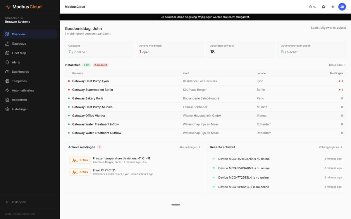
- Show output frequency, current and power of every drive on one dashboard.
- Send an alert when the trip factor is not 0, so you know a drive stopped on a fault.
- Keep a history of heat sink temperature and current to spot an overloaded motor.
- Change the frequency setpoint or ramp times remotely without going to the cabinet.
- Track run hours and power-on hours to plan fan and capacitor replacement.
Installation
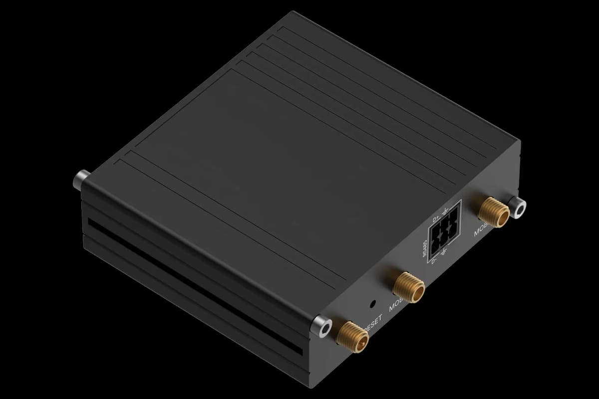
Connect SP (+) and SN (-) of the drive to RS485 A and B of the ModbusCloud Gateway and switch on the termination DIP switch on the last device.
Set station number C072, speed C071 and parity C074 on the keypad; the factory setting is station 1, 9600 baud, no parity.
Set A001 and A002 to 03 if the drive should take frequency and run command over Modbus.
In ModbusCloud, add a Modbus device with these settings and import this template.
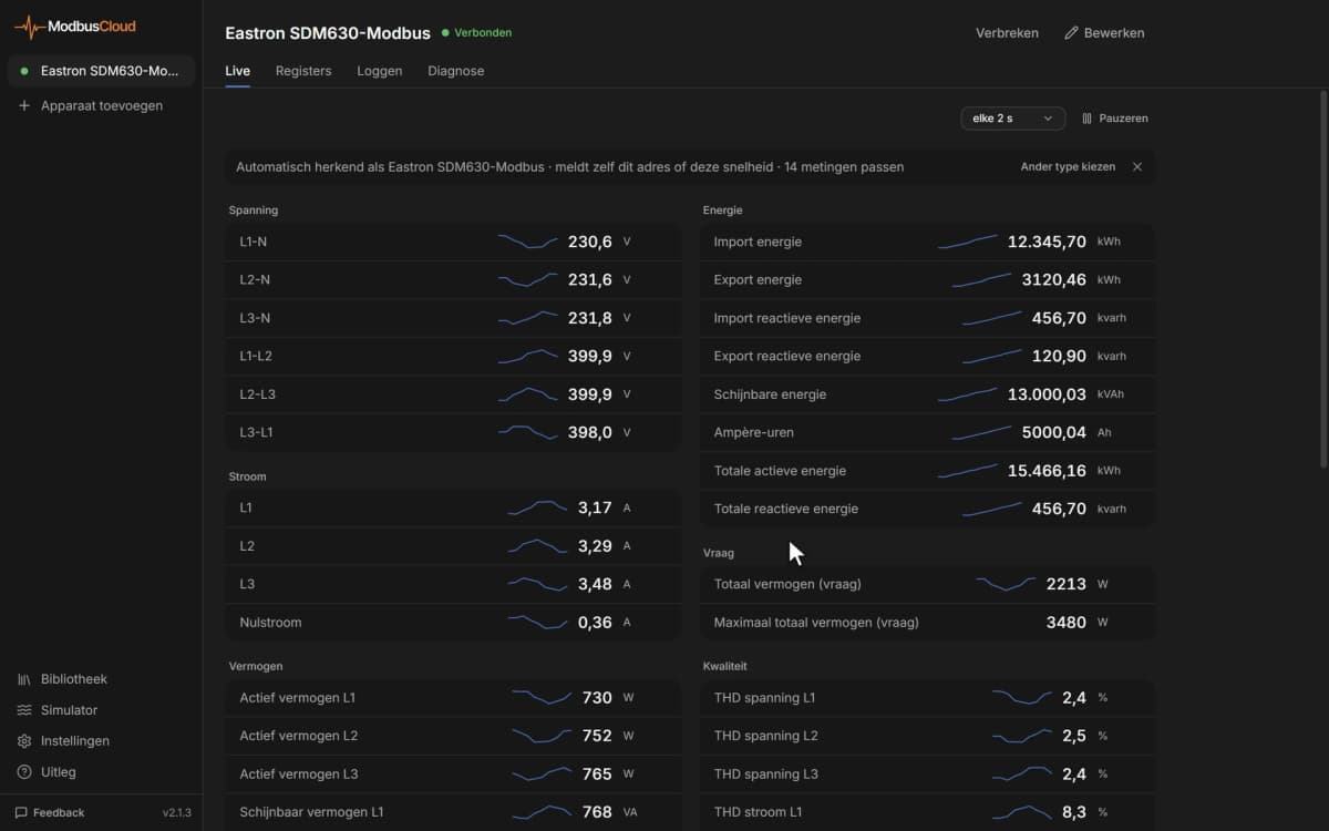
Check that output frequency and DC bus voltage come in.
Things to watch for
The drive does not answer on the bus. What should I check?
Compare station number, speed, parity and stop bits (C072, C071, C074, C075) with the device settings in ModbusCloud, and swap SP and SN if needed. Use the termination resistor only at the two ends of the bus. Changed communication settings take effect after a power cycle.
Why does the drive ignore the run command or frequency I write?
The drive only takes frequency and run command over Modbus when A001 and A002 are set to 03. Otherwise it keeps following the keypad or the terminals, even though the write is accepted.
Are written parameters kept after a power cycle?
A write goes to RAM first. Write 1 to the Writing to EEPROM register to store all data, or use EEPROM write mode for a single change. The EEPROM allows about 100,000 writes, so do not store on every change.
What should I keep in mind when writing parameters?
Many parameters can only be changed while the drive is stopped, and the drive rejects values outside the listed range. Check limits such as maximum frequency and current before you write, because a wrong ramp or limit changes how the motor behaves.
Can I connect several drives to one bus?
Yes. Give every drive its own station number from 1 to 247 and add each one as a separate Modbus device in ModbusCloud. Terminate only the first and last device on the bus.




Want to see how it works?