

SMA StpSe Battery
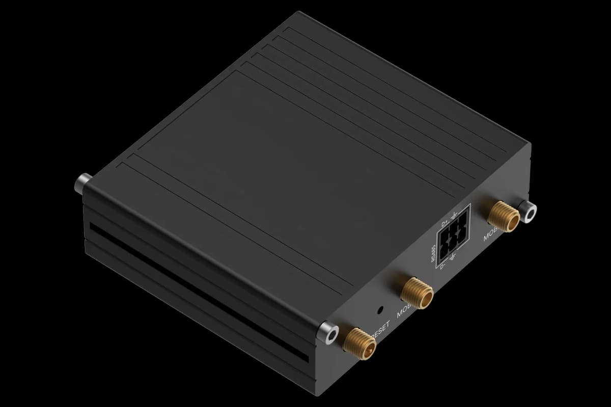
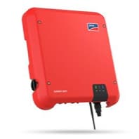
The SMA Sunny Tripower Smart Energy (STPSE) is a three-phase hybrid inverter with an integrated battery interface, designed for residential and small-commercial PV storage systems. This ModbusCloud template reads the complete battery dataset over Modbus TCP, including state of charge, DC voltage and current, instantaneous charge and discharge power, cumulative and lifetime energy counters, capacity, and current limits. Write registers let you send an active-power setpoint, select control mode, and issue a reactive-power setpoint. Having all battery metrics in one portal view makes SMA StpSe Battery straightforward to commission, trend, and alarm.
- Protocol
- Modbus TCP
- Connection
- Ethernet, Modbus TCP
- Registers
- 16, read and write
- Brand
- SMA
- Last updated
Registers (16)
13 read, 3 write
| Name | Unit | Access | Address (Hidden until you enter your email) | Function (hidden) | Type (hidden) |
|---|---|---|---|---|---|
| current | A | Read | |||
| soc | % | Read | |||
| voltage | V | Read | |||
| bat_status | Read | ||||
| cur_bat_cha | W | Read | |||
| cur_bat_dsch | W | Read | |||
| bat_chrg | Wh | Read | |||
| bat_dsch | Wh | Read | |||
| charge_max_current | A | Read | |||
| discharge_max_current | A | Read | |||
| act_bat_chrg | Wh | Read | |||
| act_bat_dsch | Wh | Read | |||
| capacity | Wh | Read | |||
| set_active_power | W | Write | |||
| set_control_mode | Write | ||||
| set_reactive_power | W | Write |
Loading registers…
Send your device list
If a device is not in the library yet, we build the template for free as soon as we have the register data.
Use cases
- Monitor battery state of charge hourly to detect capacity fade across multiple charge cycles.
- Compare instantaneous charge and discharge power against seasonal PV yield patterns.
- Alert on battery operating status changes to catch fault conditions before they affect backup readiness.
- Track cumulative charge and discharge energy counters to calculate round-trip efficiency over time.
- Verify that charge and discharge current limits reported by the BMS stay within the configured thresholds.
Installation
Enable Modbus TCP on the Sunny Tripower Smart Energy through the device web interface under Settings, then External Communication, and activate the TCP Server option.
Connect the inverter to the same LAN segment as the ModbusCloud Gateway using a standard Ethernet cable on port 502; confirm the inverter has a static or reserved IP address.
In your ModbusCloud portal, add the Gateway, import the SMA StpSe Battery template, and enter the inverter's IP address together with its configured Modbus unit ID.
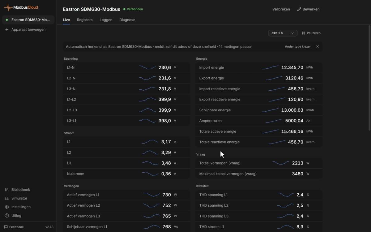
Spot-check the soc register (address 30845) and voltage register (address 30851) in the live data view to confirm values are plausible before enabling alerts or write-register automation.
Things to watch for
Why does the gateway return error code 11 on every poll?
Error code 11 means the Modbus unit ID in your portal does not match the unit ID configured on the inverter. Open the inverter web interface, note the unit ID under the Modbus or External Communication section, and update the unit ID field in your ModbusCloud template assignment to match exactly.
The cur_bat_cha and cur_bat_dsch registers both read NaN. Why?
SMA documentation notes these registers return NaN when no battery inverter is detected in the system. Confirm the battery is powered, the BMS communication cable is connected to the inverter, and the inverter has completed its initialisation sequence before polling those addresses.
64-bit counters at addresses 31397 and 31401 look corrupt. What is wrong?
64-bit SMA registers must be read as a single contiguous 64-bit operation. Reading them as two separate 32-bit requests can produce inconsistent half-values. Ensure the ModbusCloud Gateway reads the full four-register block in one function-code 3 request, which the template is configured to do by default.
Is it safe to write to set_active_power and set_control_mode in normal operation?
Exercise caution. Writing an active-power setpoint via register 40149 without first enabling external control through set_control_mode (40151) may be ignored or cause unexpected behaviour. Never write these registers cyclically in a tight loop; SMA documentation warns that cyclical writes to non-control parameters can damage flash memory. Test with small setpoint increments and confirm the inverter responds as expected before deploying automated control.

Knowledge base articles for this device
Want to see how it works?