


Socomec DIRIS A-20
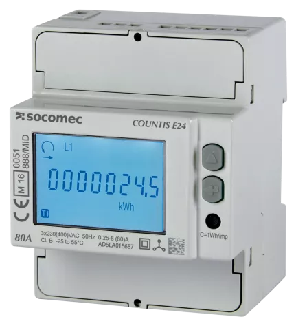
Panel multifunction meter for currents, voltages, power, energy and harmonics in switchboards.
The Socomec DIRIS A-20 is a multifunction panel meter that measures currents, voltages, power and energy in low voltage switchboards. This Modbus RTU template reads power per phase, energy, power factor, maximum averages and harmonics, and lets you set the CT ratio, pulse output and alarm from ModbusCloud.
- Protocol
- Modbus RTU
- Connection
- RS485, 9600 baud
- Registers
- 258, read and write
- Brand
- Socomec
- Key readings
- Phase currents · Phase and line voltages · Frequency · Active power · Reactive power · Power factor · Active energy · THD
- Available commands
- CT primary and secondary · Network type · Pulse output · Alarm thresholds · Reset of meters
- Compatible models
- DIRIS A20 with RS485 JBUS/MODBUS module (4825 0A20, 48250200, 48250A20)
- Last updated
Registers (258)
255 read, 30 write
| Name | Unit | Access | Address (Hidden until you enter your email) | Function (hidden) | Type (hidden) |
|---|---|---|---|---|---|
| Total Active Power | kW | Read | |||
| Current Phase 1 | A | Read | |||
| Current Phase 2 | A | Read | |||
| Current Phase 3 | A | Read | |||
| Neutral Current | A | Read | |||
| Voltage V1 | V | Read | |||
| Voltage V2 | V | Read | |||
| Voltage V3 | V | Read | |||
| Voltage U12 | V | Read | |||
| Voltage U23 | V | Read | |||
| Voltage U31 | V | Read | |||
| Frequency | Hz | Read | |||
| Total Reactive Power | kvar | Read | |||
| Total Apparent Power | kVA | Read | |||
| Total Power Factor | Read | ||||
| Active Power Phase 1 | kW | Read | |||
| Reactive Power Phase 1 | kvar | Read | |||
| Apparent Power Phase 1 | kVA | Read | |||
| Power Factor Phase 1 | Read | ||||
| Active Power Phase 2 | kW | Read | |||
| Reactive Power Phase 2 | kvar | Read | |||
| Apparent Power Phase 2 | kVA | Read | |||
| Power Factor Phase 2 | Read | ||||
| Active Power Phase 3 | kW | Read | |||
| Reactive Power Phase 3 | kvar | Read | |||
| Apparent Power Phase 3 | kVA | Read | |||
| Power Factor Phase 3 | Read | ||||
| Hour Meter | h | Read | |||
| Active Energy Import | kWh | Read | |||
| Reactive Energy Import | kvarh | Read | |||
| Hour Meter Energy Table | h | Read | |||
| Max Avg Current I1 | A | Read | |||
| Max Avg Current I2 | A | Read | |||
| Max Avg Current I3 | A | Read | |||
| Max Avg Current In | A | Read | |||
| Max Avg Active Power Import | kW | Read | |||
| Max Avg Active Power Export | kW | Read | |||
| Max Avg Reactive Power Import | kvar | Read | |||
| Max Avg Reactive Power Export | kvar | Read | |||
| Max Avg Apparent Power | kVA | Read | |||
| THD U12 | % | Read | |||
| THD U23 | % | Read | |||
| THD U31 | % | Read | |||
| THD V1 | % | Read | |||
| THD V2 | % | Read | |||
| THD V3 | % | Read | |||
| THD I1 | % | Read | |||
| THD I2 | % | Read | |||
| THD I3 | % | Read | |||
| THD In | % | Read | |||
| Alarm Lower Threshold Parameter | Read | ||||
| Alarm Lower Threshold Value | Read | ||||
| Alarm Upper Threshold Parameter | Read | ||||
| Alarm Upper Threshold Value | Read | ||||
| Alarm Duration | Read | ||||
| Options Fitted | Read | ||||
| Option Slot 1 | Read | ||||
| Option Slot 2 | Read | ||||
| Network Type | Read and write | ||||
| CT Secondary | A | Read and write | |||
| CT Primary | A | Read and write | |||
| Network Type Advanced | Read and write | ||||
| CT Secondary Advanced | A | Read and write | |||
| CT Primary Advanced | A | Read and write | |||
| Imax Synchronisation | Read and write | ||||
| Pmax Synchronisation | Read and write | ||||
| Output Allocation | Read and write | ||||
| Pulse Weight | Read and write | ||||
| Pulse Length | Read and write | ||||
| Hour Meter Type | Read and write | ||||
| Hour Meter Start Value | Read and write | ||||
| Alarm Type | Read and write | ||||
| Alarm Delay | s | Read and write | |||
| Alarm Upper Threshold | Read and write | ||||
| Alarm Lower Threshold | Read and write | ||||
| Alarm Hysteresis | Read and write | ||||
| Alarm Relay Mode | Read and write | ||||
| Reset New Table | Write | ||||
| Hour Meter Raw | h | Read | |||
| Voltage U12 Raw | V | Read | |||
| Voltage U23 Raw | V | Read | |||
| Voltage U31 Raw | V | Read | |||
| Voltage V1 Raw | V | Read | |||
| Voltage V2 Raw | V | Read | |||
| Voltage V3 Raw | V | Read | |||
| Frequency Raw | Hz | Read | |||
| Current Phase 1 Raw | A | Read | |||
| Current Phase 2 Raw | A | Read | |||
| Current Phase 3 Raw | A | Read | |||
| Current Neutral Raw | A | Read | |||
| Total Active Power Raw | kW | Read | |||
| Total Reactive Power Raw | kvar | Read | |||
| Total Apparent Power Raw | kVA | Read | |||
| Total Power Factor Raw | Read | ||||
| Active Power Phase 1 Raw | kW | Read | |||
| Reactive Power Phase 1 Raw | kvar | Read | |||
| Apparent Power Phase 1 Raw | kVA | Read | |||
| Power Factor Phase 1 Raw | Read | ||||
| Active Power Phase 2 Raw | kW | Read | |||
| Reactive Power Phase 2 Raw | kvar | Read | |||
| Apparent Power Phase 2 Raw | kVA | Read | |||
| Power Factor Phase 2 Raw | Read | ||||
| Active Power Phase 3 Raw | kW | Read | |||
| Reactive Power Phase 3 Raw | kvar | Read | |||
| Apparent Power Phase 3 Raw | kVA | Read | |||
| Power Factor Phase 3 Raw | Read | ||||
| Active Energy Import MWh | MWh | Read | |||
| Reactive Energy Import Mvarh | Read | ||||
| Current Phase 1 Old 32 Bit | A | Read | |||
| Current Phase 2 Old 32 Bit | A | Read | |||
| Current Phase 3 Old 32 Bit | A | Read | |||
| Neutral Current Old 32 Bit | A | Read | |||
| Voltage U12 Old 32 Bit | V | Read | |||
| Voltage U23 Old 32 Bit | V | Read | |||
| Voltage U31 Old 32 Bit | V | Read | |||
| Voltage V1 Old 32 Bit | V | Read | |||
| Voltage V2 Old 32 Bit | V | Read | |||
| Voltage V3 Old 32 Bit | V | Read | |||
| Frequency Old 32 Bit | Hz | Read | |||
| Total Active Power Old 32 Bit | kW | Read | |||
| Total Reactive Power Old 32 Bit | kvar | Read | |||
| Total Apparent Power Old 32 Bit | kVA | Read | |||
| Total Power Factor Old 32 Bit | Read | ||||
| Active Power Phase 1 Old 32 Bit | kW | Read | |||
| Active Power Phase 2 Old 32 Bit | kW | Read | |||
| Active Power Phase 3 Old 32 Bit | kW | Read | |||
| Reactive Power Phase 1 Old 32 Bit | kvar | Read | |||
| Reactive Power Phase 2 Old 32 Bit | kvar | Read | |||
| Reactive Power Phase 3 Old 32 Bit | kvar | Read | |||
| Apparent Power Phase 1 Old 32 Bit | kVA | Read | |||
| Apparent Power Phase 2 Old 32 Bit | kVA | Read | |||
| Apparent Power Phase 3 Old 32 Bit | kVA | Read | |||
| Power Factor Phase 1 Old 32 Bit | Read | ||||
| Power Factor Phase 2 Old 32 Bit | Read | ||||
| Power Factor Phase 3 Old 32 Bit | Read | ||||
| Max Avg Current I1 Old 32 Bit | A | Read | |||
| Max Avg Current I2 Old 32 Bit | A | Read | |||
| Max Avg Current I3 Old 32 Bit | A | Read | |||
| Max Avg Active Power Import Old 32 Bit | kW | Read | |||
| Max Avg Reactive Power Import Old 32 Bit | kvar | Read | |||
| Max Avg Apparent Power Old 32 Bit | kVA | Read | |||
| Hour Meter Old 32 Bit | h | Read | |||
| Active Energy Import Old 32 Bit | kWh | Read | |||
| Reactive Energy Import Old 32 Bit | kvarh | Read | |||
| Max Avg Current In Old 32 Bit | A | Read | |||
| Alarm In Progress | Read | ||||
| Threshold Overrun In Progress | Read | ||||
| Input Output States | Read | ||||
| Current Phase 1 Old 16 Bit | A | Read | |||
| Current Phase 2 Old 16 Bit | A | Read | |||
| Current Phase 3 Old 16 Bit | A | Read | |||
| Neutral Current Old 16 Bit | A | Read | |||
| Voltage U12 Old 16 Bit | V | Read | |||
| Voltage U23 Old 16 Bit | V | Read | |||
| Voltage U31 Old 16 Bit | V | Read | |||
| Voltage V1 Old 16 Bit | V | Read | |||
| Voltage V2 Old 16 Bit | V | Read | |||
| Voltage V3 Old 16 Bit | V | Read | |||
| Frequency Old 16 Bit | Hz | Read | |||
| Total Active Power Old 16 Bit | kW | Read | |||
| Total Reactive Power Old 16 Bit | kvar | Read | |||
| Total Apparent Power Old 16 Bit | kVA | Read | |||
| Total Power Factor Old 16 Bit | Read | ||||
| Active Power Phase 1 Old 16 Bit | W | Read | |||
| Active Power Phase 2 Old 16 Bit | W | Read | |||
| Active Power Phase 3 Old 16 Bit | W | Read | |||
| Reactive Power Phase 1 Old 16 Bit | var | Read | |||
| Reactive Power Phase 2 Old 16 Bit | var | Read | |||
| Reactive Power Phase 3 Old 16 Bit | var | Read | |||
| Apparent Power Phase 1 Old 16 Bit | VA | Read | |||
| Apparent Power Phase 2 Old 16 Bit | VA | Read | |||
| Apparent Power Phase 3 Old 16 Bit | VA | Read | |||
| Power Factor Phase 1 Old 16 Bit | Read | ||||
| Power Factor Phase 2 Old 16 Bit | Read | ||||
| Power Factor Phase 3 Old 16 Bit | Read | ||||
| Max Avg Current I1 Old 16 Bit | A | Read | |||
| Max Avg Current I2 Old 16 Bit | A | Read | |||
| Max Avg Current I3 Old 16 Bit | A | Read | |||
| Max Avg Active Power Import Old 16 Bit | W | Read | |||
| Max Avg Reactive Power Import Old 16 Bit | var | Read | |||
| Max Avg Apparent Power Old 16 Bit | VA | Read | |||
| THD I1 Old 16 Bit | % | Read | |||
| THD I2 Old 16 Bit | % | Read | |||
| THD I3 Old 16 Bit | % | Read | |||
| THD In Old 16 Bit | % | Read | |||
| THD U12 Old 16 Bit | % | Read | |||
| THD U23 Old 16 Bit | % | Read | |||
| THD U31 Old 16 Bit | % | Read | |||
| THD V1 Old 16 Bit | % | Read | |||
| THD V2 Old 16 Bit | % | Read | |||
| THD V3 Old 16 Bit | % | Read | |||
| Max Avg Current In Old 16 Bit | A | Read | |||
| Active Energy Low Old 16 Bit | kWh | Read | |||
| Active Energy High Old 16 Bit | Read | ||||
| Reactive Energy Low Old 16 Bit | kvarh | Read | |||
| Reactive Energy High Old 16 Bit | Read | ||||
| Current Phase 1 Old Table B | A | Read | |||
| Current Phase 2 Old Table B | A | Read | |||
| Current Phase 3 Old Table B | A | Read | |||
| Neutral Current Old Table B | A | Read | |||
| Voltage U12 Old Table B | V | Read | |||
| Voltage U23 Old Table B | V | Read | |||
| Voltage U31 Old Table B | V | Read | |||
| Voltage V1 Old Table B | V | Read | |||
| Voltage V2 Old Table B | V | Read | |||
| Voltage V3 Old Table B | V | Read | |||
| Frequency Old Table B | Hz | Read | |||
| Total Active Power Old Table B | kW | Read | |||
| Total Reactive Power Old Table B | kvar | Read | |||
| Total Apparent Power Old Table B | kVA | Read | |||
| Total Power Factor Old Table B | Read | ||||
| Max Avg Current I1 Old Table B | A | Read | |||
| Max Avg Current I2 Old Table B | A | Read | |||
| Max Avg Current I3 Old Table B | A | Read | |||
| Max Avg Current In Old Table B | A | Read | |||
| Max Avg Active Power Import Old Table B | kW | Read | |||
| Active Power Phase 1 Old Table B | kW | Read | |||
| Active Power Phase 2 Old Table B | kW | Read | |||
| Active Power Phase 3 Old Table B | kW | Read | |||
| Reactive Power Phase 1 Old Table B | kvar | Read | |||
| Reactive Power Phase 2 Old Table B | kvar | Read | |||
| Reactive Power Phase 3 Old Table B | kvar | Read | |||
| Apparent Power Phase 1 Old Table B | kVA | Read | |||
| Apparent Power Phase 2 Old Table B | kVA | Read | |||
| Apparent Power Phase 3 Old Table B | kVA | Read | |||
| Power Factor Phase 1 Old Table B | Read | ||||
| Power Factor Phase 2 Old Table B | Read | ||||
| Power Factor Phase 3 Old Table B | Read | ||||
| Max Avg Reactive Power Old Table B | kvar | Read | |||
| Max Avg Apparent Power Old Table B | kVA | Read | |||
| Active Energy Low Old Table B | kWh | Read | |||
| Active Energy High Old Table B | Read | ||||
| Reactive Energy Low Old Table B | kvarh | Read | |||
| Reactive Energy High Old Table B | Read | ||||
| Hour Meter Low Old Table B | h | Read | |||
| Hour Meter High Old Table B | Read | ||||
| THD I1 Old Table | % | Read | |||
| THD I2 Old Table | % | Read | |||
| THD I3 Old Table | % | Read | |||
| THD U12 Old Table | % | Read | |||
| THD U23 Old Table | % | Read | |||
| THD U31 Old Table | % | Read | |||
| THD V1 Old Table | % | Read | |||
| THD V2 Old Table | % | Read | |||
| THD V3 Old Table | % | Read | |||
| Options Fitted Old Table | Read | ||||
| Option Slot 1 Old Table | Read | ||||
| Option Slot 2 Old Table | Read | ||||
| Network Type Old Table | Read and write | ||||
| CT Secondary Old Table | A | Read and write | |||
| CT Primary Old Table | A | Read and write | |||
| Imax Synchronisation Old Table | Read and write | ||||
| Pmax Synchronisation Old Table | Read and write | ||||
| Output Allocation Old Table | Read and write | ||||
| Pulse Weight Old Table | Read and write | ||||
| Pulse Length Old Table | Read and write | ||||
| Reset Old Table | Write | ||||
| Save Settings | Write |
Loading registers…
Send your device list
If a device is not in the library yet, we build the template for free as soon as we have the register data.
Use cases
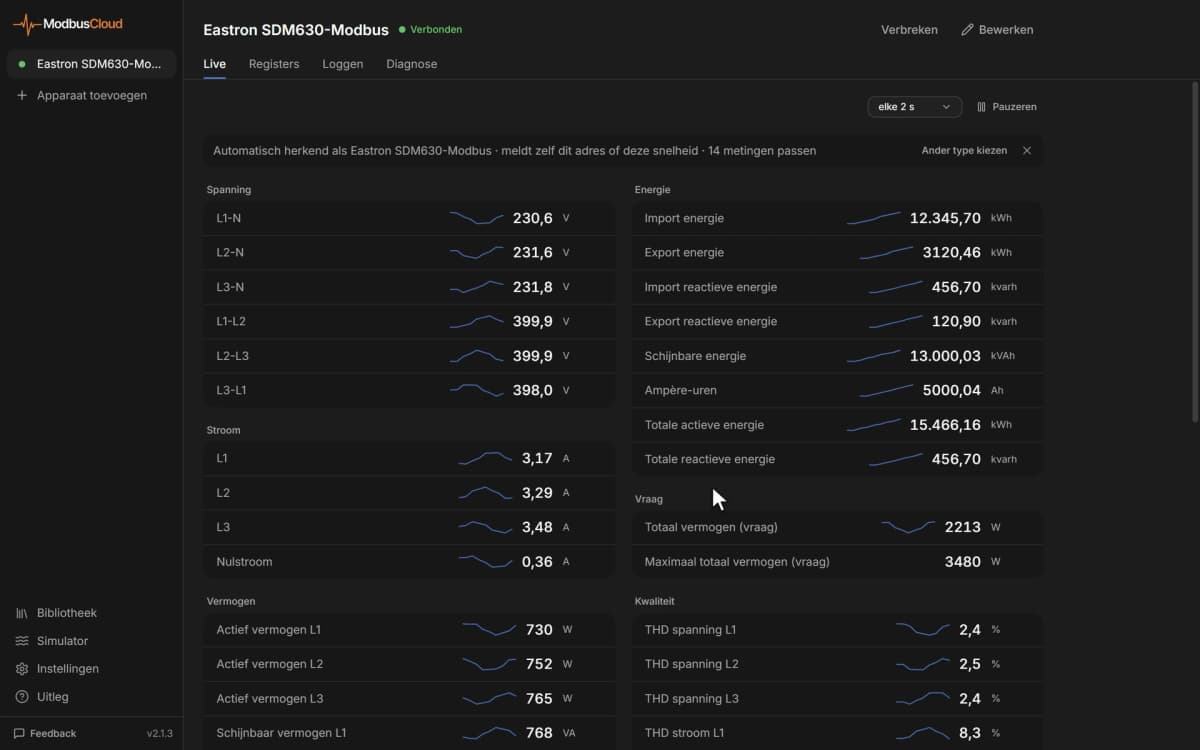
- Show power, current and power factor of every switchboard feeder on one dashboard.
- Get an email alert when a phase current or the neutral current passes a threshold.
- Track imported energy per month for each feeder or tenant from the 365 day history.
- Watch voltage and current THD to spot harmonic problems from drives or LED lighting.
- Check maximum average power against the contracted capacity of the connection.
Installation
Fit the RS485 option module on the back of the meter with the power off.
Wire A and B of the module to the RS485 port of the ModbusCloud Gateway and switch on the 120 ohm terminator at the end of the bus.
Set address, speed, parity and stop bits in the COM menu of the meter.
In ModbusCloud, add a Modbus device with the same settings and import this template.
Check that Total Active Power and the voltages match the display of the meter.
Things to watch for
The meter does not answer. What should I check?
Check that the RS485 option module is fitted, then compare address, speed, parity and stop bits in the COM menu with ModbusCloud. Swap A and B if it still stays silent. On long buses with many meters a repeater can be needed, because the module needs a clean RS485 signal.
Why are there several registers for the same value?
The meter has a newer and an older register table, with 32-bit and 16-bit versions of the same values. Use the registers without Old or Raw in the name. The Raw values are before the CT and VT ratio, so you multiply them yourself.
Currents and power are far too small or too large. Why?
Check CT primary and CT secondary on the meter. The main registers already include the CT ratio. If the CT settings do not match the installed transformers, every current, power and energy value is off by the same factor.
How do I change a setting or reset the meter over Modbus?
Write the new value, for example CT Primary, and then write 0 to Save Settings so the meter keeps it; the meter does not answer that save command. Reset registers take a bit mask. Agree resets with the owner, because energy and maximum values are lost.


Want to see how it works?