

SunSpec Model 126 — Static Volt-VAR
SunSpec Model 126 is an open interoperability standard for static Volt-VAR control on grid-tied inverters and distributed energy resources. This Modbus TCP template covers the model header registers, curve selection and enable controls (actcrv, modena), timing registers (wintms, rvrttms, rmptms), and the read-only capability descriptors (ncrv, npt) together with their three scale-factor registers (v_sf, deptref_sf, rmpincdec_sf). Any SunSpec-compliant inverter implementing Model 126 can be connected to the ModbusCloud Gateway and monitored or configured from your portal without manual register mapping.
- Protocol
- Modbus TCP
- Connection
- Ethernet, Modbus TCP
- Registers
- 12, read and write
- Brand
- SunSpec
- Compatible models
- SunSpec Model 132 — Volt-Watt
- Last updated
Registers (12)
12 read, 5 write
| Name | Unit | Access | Address (Hidden until you enter your email) | Function (hidden) | Type (hidden) |
|---|---|---|---|---|---|
| id | Read | ||||
| l | Read | ||||
| actcrv | Read and write | ||||
| modena | Read and write | ||||
| wintms | Secs | Read and write | |||
| rvrttms | Secs | Read and write | |||
| rmptms | Secs | Read and write | |||
| ncrv | Read | ||||
| npt | Read | ||||
| v_sf | Read | ||||
| deptref_sf | Read | ||||
| rmpincdec_sf | Read |
Loading registers…
Send your device list
If a device is not in the library yet, we build the template for free as soon as we have the register data.
Use cases
- Verify that the correct Volt-VAR curve is active after a grid-code change by polling the actcrv register in your dashboard.
- Monitor the modena enable flag across multiple sites to confirm Volt-VAR mode has not been inadvertently disabled during maintenance.
- Track the rvrttms reversion timeout setting to ensure automatic fallback to the default curve is configured per utility requirements.
- Alert when the wintms window timer is set to zero, which removes transition delay and may cause abrupt reactive-power steps on the grid.
- Compare ncrv and npt read-only capability values against utility requirements to confirm the inverter supports sufficient curve resolution.
Installation
Enable Modbus TCP on the inverter or DER controller under the communication or Modbus section of its web interface, and note the IP address and TCP port (typically 502).
Connect the inverter to the same LAN segment as the ModbusCloud Gateway, verify IP reachability with a ping, and confirm no firewall blocks port 502.
In your ModbusCloud portal, add the Gateway, import the SunSpec Model 126 template, and enter the device IP address, port, and Modbus unit ID matching the inverter configuration.
Read back the id register and confirm it returns 126, then check ncrv and npt to verify the inverter reports the expected curve capacity before writing any setpoints.
Things to watch for
The id register returns a value other than 126. Why?
The SunSpec model block for Model 126 may be located at a different offset on this inverter. SunSpec devices use a self-describing chain of models starting at a base address (commonly 40001). Scan forward through the chain using the l (length) register of each model until you reach the block whose id field equals 126, then use that block's start address.
Volt-VAR mode is enabled but the inverter does not respond. What now?
Confirm modena is written as 1 and that actcrv points to a valid curve index between 1 and ncrv. Some implementations require the curve data registers (V and VAr points in the repeating block) to be populated before the model header enable flag is accepted. Also check that no firmware-level grid-code lock overrides remote Modbus control.
Scale-factor registers v_sf or deptref_sf read as 0x8000. Is that correct?
A value of 0x8000 is the SunSpec not-a-number (NaN) sentinel, meaning the scale factor is not supported by this device. If the scale factor is NaN, treat the associated curve point values as unscaled integers. Verify firmware is up to date, as some older versions report NaN for optional scale factors even when the feature is active.
Is it safe to write actcrv or modena while the inverter is producing power?
Writing actcrv switches the reactive-power curve immediately (subject to wintms delay and rmptms ramp). An abrupt curve switch during high-generation periods can cause a step change in reactive power that trips protection relays or violates grid-code ramp-rate limits. Always use wintms and rmptms to stage transitions, and test changes during low-load conditions before applying them to live production sites.
Knowledge base articles for this device
SunSpec Modbus: one register map for many inverters
SunSpec Modbus is the open register map SMA, Fronius, SolarEdge and Kostal share. The layout, int+SF vs float, the TCP port per brand and reading a mixed fleet.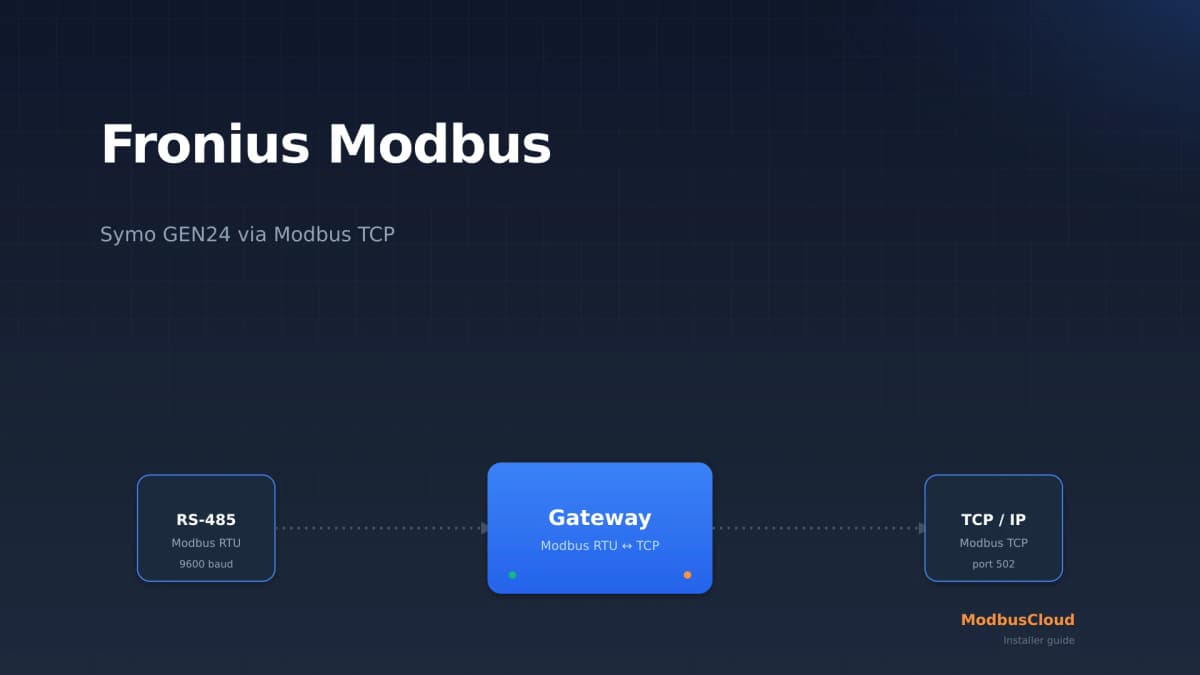
Fronius Modbus: read a Symo GEN24 over Modbus TCP
Fronius Modbus explained: enable Modbus TCP on the Symo GEN24 on port 502, choose between int+SF and float, read the right SunSpec registers and scale them correctly. Practical guide for solar installers.
SMA Modbus: reading a Sunny Boy over Modbus TCP (installers)
SMA Modbus explained: enable the Modbus TCP server on port 502, choose between the SMA profile (unit ID 3) and SunSpec (unit ID 126), read the right registers, and handle the NaN values at night. Practical guide for installers.
Want to see how it works?