
Vertiv Liebert PDX and PCW (iCOM 3)
Precision cooling for server rooms with temperatures, humidity, alarms and setpoints over Modbus TCP.
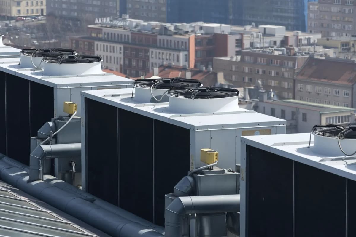
The Vertiv Liebert PDX is a direct expansion precision cooling unit for server rooms and data centres, and the Liebert PCW is its chilled water counterpart, both run by the Liebert iCOM 3 controller. This Modbus TCP template reads temperatures, humidity, pressures, alarms and working hours and lets you write on/off, setpoints and settings from ModbusCloud.
- Protocol
- Modbus TCP
- Connection
- Ethernet, Modbus TCP
- Registers
- 659, read and write
- Brand
- Vertiv
- Key readings
- Return temperature · Supply temperature · Return humidity · Discharge pressure · Fan speed · Common alarm active · Energy consumption
- Available commands
- Unit on/off · Alarm reset · Return temperature setpoint · Relative humidity setpoint
- Compatible models
- Liebert PDX with iCOM 3, V1A application · Liebert PCW with iCOM 3, V1A application · Vertiv Liebert PDX direct expansion perimeter cooling unit · Vertiv Liebert PCW chilled water perimeter cooling unit
- Last updated
Registers (659)
659 read, 189 write
| Name | Unit | Access | Address (Hidden until you enter your email) | Function (hidden) | Type (hidden) |
|---|---|---|---|---|---|
| Current Temperature Setpoint (Used by Application) | °C | Read | 3 | FC03 | uint16 |
| Actual Humidity Setpoint (Used by Application) | Read | 17 | FC03 | uint16 | |
| Current Fan Speed Setpoint (Used by Application) | Read | 30 | FC03 | uint16 | |
| Static Pressure Local Value | Pa | Read | 38 | FC03 | int16 |
| Static Pressure System Value | Pa | Read | 39 | FC03 | int16 |
| Suction Pressure Value Circ 1 | bar | Read | |||
| Suction Pressure Value Circ 2 | bar | Read | |||
| Discharge Pressure Value Circ 1 | bar | Read | |||
| Discharge Pressure Value Circ 2 | bar | Read | |||
| Suction Temperature Value Circ 1 | °C | Read | |||
| Suction Temperature Value Circ 2 | °C | Read | |||
| Discharge Temperature Value Circ 1 | °C | Read | |||
| Discharge Temperature Value Circ 2 | °C | Read | |||
| Return Temperature 1 Value | °C | Read | |||
| Return Temperature 2 Value | °C | Read | |||
| Return Temperature 3 Value | °C | Read | |||
| Return Temperature 4 Value | °C | Read | |||
| Return Temperature Value (Result) | °C | Read | |||
| Return Humidity 1 Value | % | Read | |||
| Return Humidity 2 Value | % | Read | |||
| Return Humidity 3 Value | % | Read | |||
| Return Humidity 4 Value | % | Read | |||
| Return Humidity Value (Result) | Read | ||||
| Supply Temperature 1 Value | °C | Read | |||
| Supply Temperature 2 Value | °C | Read | |||
| Supply Temperature 3 Value | °C | Read | |||
| Supply Temperature Value (Result) | °C | Read | |||
| Supply Fan Safe Value | °C | Read | |||
| Outdoor Temperature Value | °C | Read | |||
| Glycol Temperature Value | °C | Read | |||
| Remote Temperature 1 Value | °C | Read | |||
| Remote Temperature 2 Value | °C | Read | |||
| Remote Temperature 3 Value | °C | Read | |||
| Remote Temperature 4 Value | °C | Read | |||
| Remote Temperature 5 Value | °C | Read | |||
| Remote Temperature 6 Value | °C | Read | |||
| Remote Temperature 7 Value | °C | Read | |||
| Remote Temperature 8 Value | °C | Read | |||
| Remote Temperature 9 Value | °C | Read | |||
| Remote Temperature 10 Value | °C | Read | |||
| Remote Temperature Value (Result) | °C | Read | |||
| Remote Humidity 1 Value | % | Read | |||
| Remote Humidity 2 Value | % | Read | |||
| Remote Humidity 3 Value | % | Read | |||
| Remote Humidity 4 Value | % | Read | |||
| Remote Humidity 5 Value | % | Read | |||
| Remote Humidity 6 Value | % | Read | |||
| Remote Humidity 7 Value | % | Read | |||
| Remote Humidity 8 Value | % | Read | |||
| Remote Humidity 9 Value | % | Read | |||
| Remote Humidity 10 Value | % | Read | |||
| Remote Humidity Value (Result) | % | Read | |||
| Optional Sensor Temperature 1 Value | °C | Read | |||
| Optional Sensor Temperature 2 Value | °C | Read | |||
| Optional Sensor Temperature 3 Value | °C | Read | |||
| Optional Sensor Humidity 1 Value | % | Read | |||
| Optional Sensor Humidity 2 Value | % | Read | |||
| Optional Sensor Humidity 3 Value | % | Read | |||
| Air Eco Temperature Value | °C | Read | |||
| Air Eco Humidity Value | % | Read | |||
| Inlet Water Temperature C1 Value | °C | Read | |||
| Outlet Water Temperature C1 Value | °C | Read | |||
| Inlet Water Temperature C2 Value | °C | Read | |||
| Outlet Water Temperature C2 Value | °C | Read | |||
| Water Flow Circ 1 Value (l/s) | l/s | Read | |||
| Water Flow Circ 2 Value (l/s) | l/s | Read | |||
| Cool Gross Circ 1 Value | kW | Read | |||
| Cool Gross Circ 2 Value | kW | Read | |||
| System Return Temperature Value | °C | Read | |||
| System Return Humidity Value | % | Read | |||
| System Supply Temperature Value | °C | Read | |||
| System Remote Temperature Value | °C | Read | |||
| System Remote Humidity Value | % | Read | |||
| Input RMS A-N | V | Read | |||
| Input RMS B-N | V | Read | |||
| Input RMS C-N | V | Read | |||
| Input RMS A-B | V | Read | |||
| Input RMS B-C | V | Read | |||
| Input RMS C-A | V | Read | |||
| Input RMS Current Phase A | A | Read | |||
| Input RMS Current Phase B | A | Read | |||
| Input RMS Current Phase C | A | Read | |||
| Instantaneous Power | W | Read | |||
| Energy Consumption | kWh | Read | |||
| Water Flow Circ 1 Value (m3/h) | m³/h | Read | |||
| Water Flow Circ 2 Value (m3/h) | m³/h | Read | |||
| Analog Output 1 Value | % | Read | |||
| Analog Output 2 Value | % | Read | |||
| Analog Output 3 Value | % | Read | |||
| Analog Output 4 Value | % | Read | |||
| Analog Output 5 Value | % | Read | |||
| Evaporator Fan 1 Status (Modbus) | Read | ||||
| Evaporator Fan 2 Status (Modbus) | Read | ||||
| Evaporator Fan 3 Status (Modbus) | Read | ||||
| Evaporator Fan 4 Status (Modbus) | Read | ||||
| Evaporator Fan 5 Status (Modbus) | Read | ||||
| Evaporator Fan 6 Status (Modbus) | Read | ||||
| Compressor 1 Circ 1 Status | Read | ||||
| Compressor 1 Circ 1 Request | % | Read | |||
| Compressor 2 Circ 1 Status | Read | ||||
| Compressor 2 Circ 1 Request | % | Read | |||
| Compressor 1 Circ 2 Status | Read | ||||
| Compressor 1 Circ 2 Request | % | Read | |||
| Compressor 2 Circ 2 Status | Read | ||||
| Compressor 2 Circ 2 Request | % | Read | |||
| CW2 Opening Position | % | Read | |||
| Condenser 1 Request | % | Read | |||
| Condenser 1 Fan/Valve 1 Status (Modbus) | Read | ||||
| Condenser 1 Fan/Valve 2 Status (Modbus) | Read | ||||
| Condenser 1 Fan/Valve 3 Status (Modbus) | Read | ||||
| Condenser 1 Fan/Valve 4 Status (Modbus) | Read | ||||
| Condenser 2 Request | % | Read | |||
| Condenser 2 Fan/Valve 1 Status (Modbus) | Read | ||||
| Condenser 2 Fan/Valve 2 Status (Modbus) | Read | ||||
| Condenser 2 Fan/Valve 3 Status (Modbus) | Read | ||||
| Condenser 2 Fan/Valve 4 Status (Modbus) | Read | ||||
| Humidifier Status | Read | ||||
| Dehumidification Status | Read | ||||
| Heating Request | % | Read | |||
| Cooling Request (DX/CW) | % | Read | |||
| Humidification Request | % | Read | |||
| Dehumidification Request | % | Read | |||
| Fan Request | % | Read | |||
| Ultracapacitor/ATS | Read | ||||
| Unit Status | Read | ||||
| System Fan Speed Request | % | Read | |||
| System FC Request | % | Read | |||
| System DX/CW Request | % | Read | |||
| System Heating Request | % | Read | |||
| System Humidification Request | % | Read | |||
| System Dehumidification Request | % | Read | |||
| Electrode Humidifier Current | A | Read | |||
| Electrode Humidifier Conductivity | Read | ||||
| Electrode Humidifier Steam Production | kg/h | Read | |||
| Electrode Humidifier Cylinder State | Read | ||||
| Air Economizer Status | Read | ||||
| Power Consumption Calculator | W | Read | |||
| Frecooling Request | % | Read | |||
| Remote Humidity Value (Result) HumValRem_Act | Read | ||||
| Sel Man-Auto | Read | ||||
| PRE Working Mode | Read | ||||
| Fan Working Hours | h | Read | |||
| CW1 Working Hours | h | Read | |||
| CW2 Working Hours | h | Read | |||
| Comp 1 Circ 1 Working Hours | h | Read | |||
| Comp 2 Circ 1 Working Hours | h | Read | |||
| Comp 1 Circ 2 Working Hours | h | Read | |||
| Comp 2 Circ 2 Working Hours | h | Read | |||
| EEV Circuit 1 Working Hours | h | Read | |||
| EEV Circuit 2 Working Hours | h | Read | |||
| FC Working Hours | h | Read | |||
| Air Eco Working Hours | h | Read | |||
| PRE 1 Working Hours | h | Read | |||
| PRE 2 Working Hours | h | Read | |||
| Condenser 1 Working Hours | h | Read | |||
| Condenser 2 Working Hours | h | Read | |||
| Humidification Working Hours | h | Read | |||
| Dehumidification Working Hours | h | Read | |||
| Heating 1 Working Hours | h | Read | |||
| Heating 2 Working Hours | h | Read | |||
| Hot Gas/Hot Water Working Hours | h | Read | |||
| Pressure Prop Band | Pa | Read | |||
| CF Differential Pressure | Pa | Read | |||
| Analog Input 1 Value | Read | ||||
| Analog Input 2 Value | Read | ||||
| Analog Input 3 Value | Read | ||||
| Analog Input 4 Value | Read | ||||
| Pump 1 Inlet Pressure | bar | Read | |||
| Pump 2 Inlet Pressure | bar | Read | |||
| Circuit 1 Outdoor Temperature | °C | Read | |||
| Circuit 2 Outdoor Temperature | °C | Read | |||
| EEV 1 Position | % | Read | |||
| EEV 2 Position | % | Read | |||
| Pump 1 Speed | % | Read | |||
| Pump 2 Speed | % | Read | |||
| Pump 1 Inlet Temperature | °C | Read | |||
| Pump 2 Inlet Temperature | °C | Read | |||
| Pump 1 Outlet Temperature | °C | Read | |||
| Pump 2 Outlet Temperature | °C | Read | |||
| Pump 1 State | Read | ||||
| Pump 2 State | Read | ||||
| Operating Mode | Read | ||||
| Fluid Eco Status | Read | ||||
| Daily High Control Temperature | °C | Read | |||
| Daily Low Control Temperature | °C | Read | |||
| Daily High Return Humidity | % | Read | |||
| Daily Low Return Humidity | % | Read | |||
| Cooling Control Temperature | °C | Read | |||
| Fan Control Temperature | °C | Read | |||
| Supersaver Signal | % | Read | |||
| CW1 Opening Position | % | Read | |||
| Evaporator Fan 7 Status (Modbus) | Read | ||||
| Evaporator Fan 8 Status (Modbus) | Read | ||||
| Retain Memory Error | Read | ||||
| Too Much Retain Writing | Read | ||||
| Heater High Temperature Lockout | Read | ||||
| High Return Temperature | Read | ||||
| High Supply Temperature | Read | ||||
| High Remote Temperature | Read | ||||
| Low Return Temperature | Read | ||||
| Low Supply Temperature | Read | ||||
| Low Remote Temperature | Read | ||||
| One (or More) Evaporator Fan in Alarm | Read | ||||
| One (or More) Evaporator Fan Offline | Read | ||||
| All Evaporator Fans Offline | Read | ||||
| Loss of Air Flow | Read | ||||
| BMS Offline | Read | ||||
| Low Pressure Circuit 1 | Read | ||||
| Low Pressure Circuit 2 | Read | ||||
| High Pressure Circuit 1 | Read | ||||
| High Pressure Circuit 2 | Read | ||||
| Soft High Pressure Circuit 1 | Read | ||||
| Soft High Pressure Circuit 2 | Read | ||||
| Thermal Protection Compressor 1 Circuit 1 | Read | ||||
| Thermal Protection Compressor 2 Circuit 1 | Read | ||||
| Thermal Protection Compressor 1 Circuit 2 | Read | ||||
| Thermal Protection Compressor 2 Circuit 2 | Read | ||||
| Low Suction SuperHeat Circuit 1 | Read | ||||
| Low Suction SuperHeat Circuit 2 | Read | ||||
| High Suction SuperHeat Circuit 1 | Read | ||||
| High Suction SuperHeat Circuit 2 | Read | ||||
| Return Sensor Failure (Cumulative) | Read | ||||
| Supply Sensor Failure (Cumulative) | Read | ||||
| Remote Sensor Failure (Cumulative) | Read | ||||
| Outdoor Sensor Failure | Read | ||||
| Suction Pressure Sensor Circuit 1 Failure | Read | ||||
| Suction Pressure Sensor Circuit 2 Failure | Read | ||||
| Discharge Pressure Sensor Circuit 1 Failure | Read | ||||
| Discharge Pressure Sensor Circuit 2 Failure | Read | ||||
| Suction Temperature Sensor Circuit 1 Failure | Read | ||||
| Suction Temperature Sensor Circuit 2 Failure | Read | ||||
| Discharge Temperature Sensor Circuit 1 Failure | Read | ||||
| Discharge Temperature Sensor Circuit 2 Failure | Read | ||||
| Configurable Alarm | Read | ||||
| C-Input 1 | Read | ||||
| C-Input 2 | Read | ||||
| C-Input 3 | Read | ||||
| C-Input 4 | Read | ||||
| Compressor Lockout (with PumpDown) | Read | ||||
| Compressor Lockout | Read | ||||
| Condenser 1 Failure | Read | ||||
| Condenser 2 Failure | Read | ||||
| Condensing Pump Alarm | Read | ||||
| Condensing Pump Alarm Al_CndPmpLCEvt | Read | ||||
| Condensing Pump Alarm Al_CndPmpSDEvt | Read | ||||
| Fire Alarm | Read | ||||
| Loss of Flow | Read | ||||
| Loss of Flow Al_FlowALLCEvt | Read | ||||
| Loss of Flow AL_FlowALSDEvt | Read | ||||
| Heater Alarm | Read | ||||
| High CW1 Temperature | Read | ||||
| High CW2 Temperature | Read | ||||
| Humidifier Problem | Read | ||||
| Configurable Warning | Read | ||||
| Water Alarm | Read | ||||
| No Power | Read | ||||
| Smoke Alarm | Read | ||||
| Clogged Filter | Read | ||||
| Stop Due to High Temp | Read | ||||
| Out Of Working Range | Read | ||||
| High Remote Humidity | Read | ||||
| Low Return Humidity | Read | ||||
| Low Remote Humidity | Read | ||||
| High Return Humidity | Read | ||||
| Soft Low Pressure Circuit 1 (MTM Only) | Read | ||||
| Force FC | Read | ||||
| Humidity Return Sensor Failure (MTM Only) | Read | ||||
| UC Missing | Read | ||||
| Conditioner/Fans Working Hours Exceeded | Read | ||||
| CW1 Valve Working Hours Exceeded | Read | ||||
| CW2 Valve Working Hours Exceeded | Read | ||||
| Comp1 Circ1 Working Hours Exceeded | Read | ||||
| Comp2 Circ1 Working Hours Exceeded | Read | ||||
| Comp1 Circ2 Working Hours Exceeded | Read | ||||
| Comp2 Circ2 Working Hours Exceeded | Read | ||||
| FC Working Hours Exceeded | Read | ||||
| AirEco Working Hours Exceeded | Read | ||||
| PRE1 Working Hours Exceeded | Read | ||||
| PRE2 Working Hours Exceeded | Read | ||||
| El. Heater1 Working Hours Exceeded | Read | ||||
| El. Heater2 Working Hours Exceeded | Read | ||||
| Hot Water/Gas Working Hours Exceeded | Read | ||||
| Condenser Fans1 Working Hours Exceeded | Read | ||||
| Condenser Fans2 Working Hours Exceeded | Read | ||||
| Humidifier Working Hours Exceeded | Read | ||||
| Dehumidification Working Hours Exceeded | Read | ||||
| VSD Circuit 1 Out of Envelope | Read | ||||
| VSD Circuit 1 Generic Event | Read | ||||
| VSD Circuit 1 Offline | Read | ||||
| VSD Circuit 1 Generic Event Al_WarnVSD_Circ1 | Read | ||||
| VSD Circuit 2 Out of Envelope | Read | ||||
| VSD Circuit 2 Generic Event | Read | ||||
| VSD Circuit 2 Offline | Read | ||||
| VSD Circuit 2 Generic Event Al_WarnVSD_Circ2 | Read | ||||
| Network Failure | Read | ||||
| No Connection to Unit 1 | Read | ||||
| One (or More) Condenser C1 Fan in Alarm | Read | ||||
| One (or More) Condenser C1 Fan Offline | Read | ||||
| All Condenser C1 Fans Offline | Read | ||||
| One (or More) Condenser C2 Fan in Alarm | Read | ||||
| One (or More) Condenser C2 Fan Offline | Read | ||||
| All Condenser C2 Fans Offline | Read | ||||
| Master Unit Not Available | Read | ||||
| HCB Offline | Read | ||||
| HCB Shut Down | Read | ||||
| Energy Meter Offline | Read | ||||
| Low Operating Pressure Circuit 1 | Read | ||||
| Low Operating Pressure Circuit 2 | Read | ||||
| Maximum Operating Pressure Circuit 2 | Read | ||||
| Maximum Operating Pressure Circuit 1 | Read | ||||
| Generic EEV Circuit 1 | Read | ||||
| Generic EEV Circuit 2 | Read | ||||
| EEV Driver Offline Circuit 1 | Read | ||||
| EEV Driver Offline Circuit 2 | Read | ||||
| All Condenser C1 Fans in Alarm | Read | ||||
| All Condenser C2 Fans in Alarm | Read | ||||
| High Discharge Temperature Circuit 1 | Read | ||||
| High Discharge Temperature Circuit 2 | Read | ||||
| Wrong Damper Position | Read | ||||
| Reduced Eco Air Flow | Read | ||||
| VSD Circuit 1 Startup Failure | Read | ||||
| VSD Circuit 2 Startup Failure | Read | ||||
| Loss of CW1 Flow | Read | ||||
| Loss of CW2 Flow | Read | ||||
| FC Off by Dehum | Read | ||||
| FC Stopped for 1 Hour by Hum | Read | ||||
| FC Stopped for 1 Hour by Dehum | Read | ||||
| FC Stopped for 1 Hour by DT3 | Read | ||||
| Dehum Stop by Low Limit 1 | Read | ||||
| Dehum Stop by Low Limit 2 | Read | ||||
| FC Lockout | Read | ||||
| Second Set Point Active | Read | ||||
| Heaters Lockout | Read | ||||
| Humidifier and Heaters Lockout | Read | ||||
| Humidifier Lockout | Read | ||||
| Standby On | Read | ||||
| Cool and Fan 100% | Read | ||||
| Ultracap Active | Read | ||||
| Power On | Read | ||||
| Power Off | Read | ||||
| Unit On | Read | ||||
| Expansion Board 1 Offline | Read | ||||
| Expansion Board 2 Offline | Read | ||||
| Heater High Temperature Probe Fail | Read | ||||
| Optional Probe 1 Fail | Read | ||||
| Air Economizer Probe Fail | Read | ||||
| Glycol Temperature Probe Fail | Read | ||||
| Optional Probe 2 Fail | Read | ||||
| Optional Probe 3 Fail | Read | ||||
| CW1 Inlet Probe Fail | Read | ||||
| CW1 Outlet Probe Fail | Read | ||||
| CW2 Inlet Probe Fail | Read | ||||
| CW2 Outlet Probe Fail | Read | ||||
| Local Static Pressure Sensor Fail | Read | ||||
| System Static Pressure Sensor Fail | Read | ||||
| CW1 Water Flow Sensor Fail | Read | ||||
| CW2 Water Flow Sensor Fail | Read | ||||
| Return System Sensor Failure | Read | ||||
| Remote System Sensor Failure | Read | ||||
| HCB Disable | Read | ||||
| Mb CW Valve 1 Offline | Read | ||||
| Mb CW Valve 2 Offline | Read | ||||
| Mb CW Valve 3 Offline | Read | ||||
| Mb CW Valve 4 Offline | Read | ||||
| Supply Water High Conductivity | Read | ||||
| Air Eco Emergency Override | Read | ||||
| Remote 1 Sensor Failure | Read | ||||
| Remote 2 Sensor Failure | Read | ||||
| Remote 3 Sensor Failure | Read | ||||
| Remote 4 Sensor Failure | Read | ||||
| Remote 5 Sensor Failure | Read | ||||
| Remote 6 Sensor Failure | Read | ||||
| Remote 7 Sensor Failure | Read | ||||
| Remote 8 Sensor Failure | Read | ||||
| Remote 9 Sensor Failure | Read | ||||
| Remote 10 Sensor Failure | Read | ||||
| Condenser Refrigerant Sensor T1 Failure | Read | ||||
| Pump1 Outlet Temp Sensor Failure | Read | ||||
| Pump1 Inlet Press Sensor Failure | Read | ||||
| Pump1 Outlet Press Sensor Failure | Read | ||||
| Condenser Refrigerant Sensor T2 Failure | Read | ||||
| Pump2 Outlet Temp Sensor Failure | Read | ||||
| Pump2 Inlet Press Sensor Failure | Read | ||||
| Pump2 Outlet Press Sensor Failure | Read | ||||
| Pump1 Failure | Read | ||||
| Pump2 Failure | Read | ||||
| Condenser 1 Outdoor Temp Sensor Failure | Read | ||||
| Condenser 2 Outdoor Temp Sensor Failure | Read | ||||
| Expansion Board 3 Offline | Read | ||||
| Expansion Board 4 Offline | Read | ||||
| Unit Off by Display | Read | ||||
| Unit Off by Remote Input | Read | ||||
| Unit Off by 3 Pos Switch | Read | ||||
| Unit Off by Monitoring | Read | ||||
| Unit Off by Timer | Read | ||||
| Unit Off by Alarm | Read | ||||
| Unit Standby Mode | Read | ||||
| Unit Manual Mode | Read | ||||
| Very Low Outdoor Temperature | Read | ||||
| Very Low Outdoor Temperature Al_CndLowAmbThrs3 | Read | ||||
| Low SuperHeat Pump 1 | Read | ||||
| High SuperHeat Pump 1 | Read | ||||
| Low SubCool Pump 1 | Read | ||||
| Low Diff Press Pump 1 | Read | ||||
| High Diff Press Pump 1 | Read | ||||
| Low SuperHeat Pump 2 | Read | ||||
| High SuperHeat Pump 2 | Read | ||||
| Low SubCool Pump 2 | Read | ||||
| Low Diff Press Pump 2 | Read | ||||
| High Diff Press Pump 2 | Read | ||||
| Pump 1 Alarm | Read | ||||
| Pump 2 Alarm | Read | ||||
| Startup Failure Pump 1 | Read | ||||
| Startup Failure Pump 2 | Read | ||||
| Startup Lock Pump 1 | Read | ||||
| Startup Lock Pump 2 | Read | ||||
| Low Start Pressure Circuit 1 | Read | ||||
| Low Start Pressure Circuit 2 | Read | ||||
| Stop On Low Pressure Circuit 1 | Read | ||||
| Stop On Low Pressure Circuit 2 | Read | ||||
| Freeze Protection Circuit 1 | Read | ||||
| Freeze Protection Circuit 2 | Read | ||||
| Low Start Pressure Circuit 1 Al_LowStartPMsgCirc1 | Read | ||||
| Low Start Pressure Circuit 2 Al_LowStartPMsgCirc2 | Read | ||||
| Capacity Derating Circuit 1 | Read | ||||
| Capacity Derating Circuit 2 | Read | ||||
| Static Pressure Out Of Range | Read | ||||
| EEV Circuit 1 Working Hours Exceeded | Read | ||||
| EEV Circuit 2 Working Hours Exceeded | Read | ||||
| EconoPhase Prop Lockout | Read | ||||
| Surge Arrester Failure | Read | ||||
| Clogged Filter Th1 | Read | ||||
| Clogged Filter Th2 | Read | ||||
| Clogged Filter Error | Read | ||||
| ATS Error | Read | ||||
| Airflow Sensor Failure | Read | ||||
| Mb Condenser Valve 1 Offline | Read | ||||
| Mb Condenser Valve 2 Offline | Read | ||||
| Mb FC Valve 1 Offline | Read | ||||
| Aux Sensor Disconnected | Read | ||||
| Unit On/Off Command | Read and write | ||||
| System On/Off Command | Read and write | ||||
| Configurable Input 1 | Read | ||||
| Configurable Input 2 | Read | ||||
| Configurable Input 3 | Read | ||||
| Configurable Input 4 | Read | ||||
| Configurable Input 5 | Read | ||||
| Configurable Input 6 | Read | ||||
| Configurable Input 7 | Read | ||||
| Configurable Input 8 | Read | ||||
| Airflow Status | Read | ||||
| Low Pressure Circ 1 Status | Read | ||||
| High Pressure Circ 1 Status | Read | ||||
| Thermal Protection Compressor 1 Circ 1 | Read | ||||
| Thermal Protection Compressor 2 Circ 1 | Read | ||||
| Low Pressure Circ 2 Status | Read | ||||
| High Pressure Circ 2 Status | Read | ||||
| Thermal Protection Compressor 1 Circ 2 | Read | ||||
| Thermal Protection Compressor 2 Circ 2 | Read | ||||
| Remote Off | Read | ||||
| 3 Position Switch | Read | ||||
| Clogged Filter CF | Read | ||||
| Heater 1 | Read | ||||
| Heater 2 | Read | ||||
| Low Limit 1 LowLim1_Lock | Read | ||||
| Low Limit 2 LowLim2_Lock | Read | ||||
| Unit On/Off Command by BMS | Read and write | ||||
| Alarm Reset by BMS | Read and write | ||||
| Generic Alarm Active | Read | ||||
| Generic Warning Active | Read | ||||
| Generic Event Active | Read | ||||
| BMS Heart Beat | Read and write | ||||
| ATS Power Supply Line in Use | Read | ||||
| ATS Power Supply 1 Status | Read | ||||
| ATS Power Supply 2 Status | Read | ||||
| Return Temperature Setpoint | °C | Read and write | |||
| Remote Temperature Setpoint | °C | Read and write | |||
| Supply Temperature Setpoint | °C | Read and write | |||
| Second Setpoint | °C | Read and write | |||
| Backup Setpoint (Temp) | °C | Read and write | |||
| Compensation Value | K | Read and write | |||
| Return Proportional Band | K | Read and write | |||
| Remote Proportional Band | K | Read and write | |||
| Supply Proportional Band | K | Read and write | |||
| Return Temperature DeadBand | K | Read and write | |||
| Remote Temperature DeadBand | K | Read and write | |||
| Supply Temperature DeadBand | K | Read and write | |||
| Relative Humidity Setpoint | % | Read and write | |||
| Absolute Humidity Setpoint | g/kg | Read and write | |||
| Dew Point Humidity Setpoint | °C | Read and write | |||
| Relative Humidity Proportional Band | % | Read and write | |||
| Absolute Humidity Proportional Band | g/kg | Read and write | |||
| Dew Point Humidity Proportional Band | K | Read and write | |||
| Relative Humidity DeadBand | % | Read and write | |||
| Absolute Humidity DeadBand | g/kg | Read and write | |||
| Dew Point Humidity DeadBand | K | Read and write | |||
| Return Fan Speed Setpoint | °C | Read and write | |||
| Remote Fan Speed Setpoint | °C | Read and write | |||
| Supply Fan Speed Setpoint | °C | Read and write | |||
| Delta Fan Speed Setpoint | K | Read and write | |||
| Static Pressure Setpoint | Pa | Read and write | |||
| Static Pressure DeadBand | Pa | Read and write | |||
| Low Limit 1 | K | Read and write | |||
| Low Limit 2 | K | Read and write | |||
| Condenser Cut-Off | bar | Read and write | |||
| Condenser 1 Setpoint | bar | Read and write | |||
| Condenser 1 Proportional Band | bar | Read and write | |||
| Condenser 2 Setpoint | bar | Read and write | |||
| Condenser 2 Proportional Band | bar | Read and write | |||
| System Temperature Setpoint | °C | Read and write | |||
| System Humidity Setpoint | Read and write | ||||
| Temperature Control | Read and write | ||||
| Compensation Type | Read and write | ||||
| Return Integration Time | s | Read and write | |||
| Remote Integration Time | s | Read and write | |||
| Supply Integration Time | s | Read and write | |||
| Humidity Control | Read and write | ||||
| Humidity Control Method | Read and write | ||||
| Fan Speed Control | Read and write | ||||
| Auto Mode | Read and write | ||||
| Fixed Fan Speed | % | Read and write | |||
| Fan Startup Speed | % | Read and write | |||
| Fan Startup Time | s | Read and write | |||
| Fan Shutdown Speed | % | Read and write | |||
| Fan Shutdown Time | s | Read and write | |||
| Minimum Speed | % | Read and write | |||
| Maximum Speed | % | Read and write | |||
| Minimum DX Speed | % | Read and write | |||
| Dehumidification Speed | % | Read and write | |||
| Humidification Speed | % | Read and write | |||
| Heating Speed | % | Read and write | |||
| No Power Speed | % | Read and write | |||
| Control Sensor Failure Speed | % | Read and write | |||
| Fan Back Draft Control | Read and write | ||||
| Fan Back Draft Control Speed | % | Read and write | |||
| High Return Temperature Event Enable | Read and write | ||||
| High Ret Temp Speed | % | Read and write | |||
| Modbus High Speed Operation | Read and write | ||||
| CW Valve Operating Mode | Read and write | ||||
| CW Main Valve | Read and write | ||||
| Daily Valve Rotation | Read and write | ||||
| Rotation Hour | Read and write | ||||
| Loss of Flow at | % | Read and write | |||
| CW Start Position | % | Read and write | |||
| CW Start Time | s | Read and write | |||
| Configurable Input 1 Setting | Read and write | ||||
| Configurable Input 2 Setting | Read and write | ||||
| Configurable Input 3 Setting | Read and write | ||||
| Configurable Input 4 Setting | Read and write | ||||
| Configurable Input 5 Setting | Read and write | ||||
| Configurable Input 6 Setting | Read and write | ||||
| Configurable Input 7 Setting | Read and write | ||||
| Configurable Input 8 Setting | Read and write | ||||
| Auto Restart Enable | Read and write | ||||
| Auto Restart Time | s | Read and write | |||
| Dehumidification Enable | Read and write | ||||
| Low Limit Probe | Read and write | ||||
| Alarm OFF by LWD | Read and write | ||||
| Alarm OFF by Loss of Airflow | Read and write | ||||
| Alarm OFF by High Supply Temp. | Read and write | ||||
| Humidifier Steam Rate | % | Read and write | |||
| Return Damper Enable | Read and write | ||||
| Return Damper Opening Time | s | Read and write | |||
| Condenser Control Type | Read and write | ||||
| Condenser Min Speed/Opening | % | Read and write | |||
| Condenser Max Speed/Opening | % | Read and write | |||
| Condenser 1 Integration Time | s | Read and write | |||
| Condenser 1 Setpoint Type | Read and write | ||||
| Condenser 2 Integration Time | s | Read and write | |||
| Condenser 2 Setpoint Type | Read and write | ||||
| High Return Temperature Event Limit | °C | Read and write | |||
| Low Return Temperature Event Enable | Read and write | ||||
| Low Return Temperature Event Limit | °C | Read and write | |||
| High Remote Temperature Event Enable | Read and write | ||||
| High Remote Temperature Event Limit | °C | Read and write | |||
| Low Remote Temperature Event Enable | Read and write | ||||
| Low Remote Temperature Event Limit | °C | Read and write | |||
| High Supply Temperature Event Enable | Read and write | ||||
| High Supply Temperature Event Limit | °C | Read and write | |||
| Low Supply Temperature Event Enable | Read and write | ||||
| Low Supply Temperature Event Limit | °C | Read and write | |||
| High Return Humidity Event Enable (Relative) | Read and write | ||||
| High Return Humidity Event Limit (Relative) | % | Read and write | |||
| Low Return Humidity Event Enable (Relative) | Read and write | ||||
| Low Return Humidity Event Limit (Relative) | % | Read and write | |||
| High Remote Humidity Event Enable (Relative) | Read and write | ||||
| High Remote Humidity Event Limit (Relative) | % | Read and write | |||
| Low Remote Humidity Event Enable (Relative) | Read and write | ||||
| Low Remote Humidity Event Limit (Relative) | % | Read and write | |||
| High Return Humidity Event Limit (Absolute) | g/kg | Read and write | |||
| Low Return Humidity Event Limit (Absolute) | g/kg | Read and write | |||
| High Remote Humidity Event Limit (Absolute) | g/kg | Read and write | |||
| Low Remote Humidity Event Limit (Absolute) | g/kg | Read and write | |||
| High Return Dew Point Event Limit | °C | Read and write | |||
| Low Return Dew Point Event Limit | °C | Read and write | |||
| High Remote Dew Point Event Limit | °C | Read and write | |||
| Low Remote Dew Point Event Limit | °C | Read and write | |||
| Analog Output 1 Setting | Read and write | ||||
| Analog Output 2 Setting | Read and write | ||||
| Analog Output 3 Setting | Read and write | ||||
| Analog Output 4 Setting | Read and write | ||||
| Analog Output 5 Setting | Read and write | ||||
| Number of Return Probes | Read and write | ||||
| Return Probes Control Mode | Read and write | ||||
| Number of Supply Probes | Read and write | ||||
| Return Control Mode | Read and write | ||||
| Number of Remote Probes | Read and write | ||||
| Remote Probes Control Mode | Read and write | ||||
| Number of Optional Probes | Read and write | ||||
| Date Day | Read and write | ||||
| Date Month | Read and write | ||||
| Date Year | Read and write | ||||
| Time Hour | Read and write | ||||
| Time Minute | Read and write | ||||
| Time Second | Read and write | ||||
| Teamwork Total Units | Read and write | ||||
| Teamwork Standby Units | Read and write | ||||
| Teamwork Mode | Read and write | ||||
| Cascade | Read and write | ||||
| El Heater High Supply Temp Counter Reset | Read and write | ||||
| Condenser Emergency Mode Delay | s | Read and write | |||
| Condenser Emergency Mode Speed/Opening | % | Read and write | |||
| Condenser Emergency Mode Enable | Read and write | ||||
| Evaporating Fans Emergency Mode Delay | s | Read and write | |||
| Evaporating Fans Emergency Mode Speed | % | Read and write | |||
| Evaporating Fans Emergency Mode Enable | Read and write | ||||
| Air Economizer Type | Read and write | ||||
| Stop Air Economizer on Clogged Filter | Read and write | ||||
| Air Economizer DT1 Type | Read and write | ||||
| Air Economizer DT1 Room Ambient Temperature Difference | K | Read and write | |||
| Air Economizer DT3 Temperature Enable | Read and write | ||||
| Air Economizer DT3 Room Temperature/Setpoint Difference | K | Read and write | |||
| Air Economizer Reduced Economizer Airflow Enable | Read and write | ||||
| Air Economizer Emergency Override Enable | Read and write | ||||
| BMS Time-Out Enable | Read and write | ||||
| BMS Timeout | s | Read and write | |||
| Static Pressure Events Enable | Read and write | ||||
| Low Static Pressure Event Limit | Pa | Read and write | |||
| High Static Pressure Event Limit | Pa | Read and write | |||
| Nominal Vol. Flow Rate (CW) | l/s | Read and write | |||
| BMS Temp. Control | Read and write | ||||
| BMS Fan Control | Read and write | ||||
| Backup Speed | % | Read and write | |||
| Backup Setpoint (Fan) | °C | Read and write | |||
| P-Band Switchback Thrs | % | Read and write | |||
| Fluid Eco DX+FC | Read and write | ||||
| Fluid Eco Lockout FC at | °C | Read and write | |||
| Fluid Eco Minimum Glycol Enable | Read and write | ||||
| Fluid Eco Minimum Glycol Temperature | °C | Read and write | |||
| Fluid Eco DT1 Type | Read and write | ||||
| Fluid Eco DT1 Value | K | Read and write | |||
| Fluid Eco DT2 Type | Read and write | ||||
| Fluid Eco DT2 Value | K | Read and write | |||
| Fluid Eco DT3 Enable | Read and write | ||||
| Fluid Eco DT3 Value | K | Read and write | |||
| Nominal Vol. Flow Rate (Fluid Economizer) | l/s | Read and write | |||
| Nominal Vol. Flow Rate (Water Condenser) | l/s | Read and write | |||
| IR Flush Rate | % | Read and write | |||
| Monitoring System of Measurement | Read and write |
Loading registers…
Send your device list
If a device is not in the library yet, we build the template for free as soon as we have the register data.
Use cases
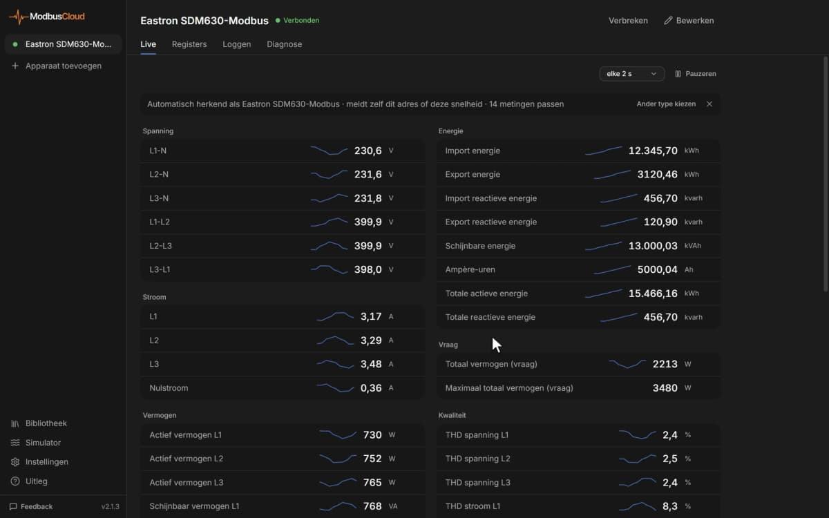
- Show return and supply temperature and humidity of every cooling unit in a server room on one ModbusCloud dashboard.
- Send an email or webhook alert as soon as the generic alarm or a high temperature warning becomes active.
- Keep 365 days of history of temperatures, fan speed and compressor requests to see how the cooling load develops.
- Compare working hours of fans and compressors across units to plan maintenance.
- Get a no data alert when the monitoring port of a unit stops answering.
Installation
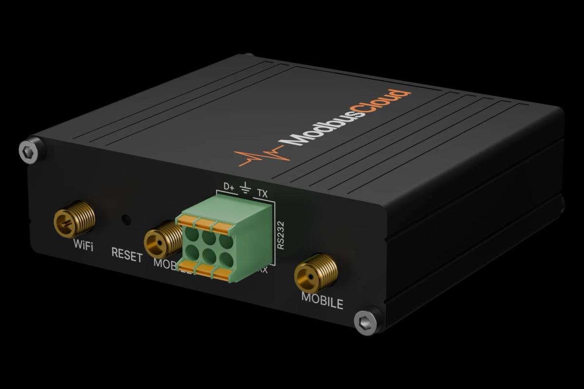
Connect the monitoring Ethernet port of the iCOM 3 to the network of the ModbusCloud Gateway, separate from the Teamwork network of the units.
Give the monitoring port an address in that network through its web page; the default is 192.168.254.200.
Check in the monitoring port that the V1A monitoring model is active and that Modbus TCP is on port 502.
In ModbusCloud, add a Modbus TCP device with that IP address, port 502 and unit ID 1, and import this template.
Check that return temperature and the generic alarm come in with sensible values.
Things to watch for
The unit does not answer on Modbus TCP. What should I check?
Make sure you use the monitoring Ethernet port and not the Teamwork port, that the IP address is in the same network as the gateway, and that a monitoring model is active in the monitoring port. Modbus TCP listens on port 502 with unit ID 1.
Why do temperatures look too high or wrong?
Values follow the unit system in the Monitoring System of Measurement register (address 417). With 1 (imperial) temperatures are in °F and pressures in psi. Set it to 0 for metric, which matches the units in this template.
Why are all registers one address off?
The Vertiv tables count from 1. This template uses the address in the Modbus message, which is the table number minus 1. If your other software shows 40001 for the first register, that is the same register.
Can I switch the unit on and off from ModbusCloud?
Yes, through the Unit On/Off command coil or the BMS on/off coil, once writing is enabled for your gateway. ModbusCloud turns writing on per gateway on request; by default the template only reads.




Want to see how it works?