
Yaskawa A1000
AC drive for induction and PM motors with run commands, speed reference and full status monitoring.
The Yaskawa A1000 is an AC drive that controls the speed and torque of induction and permanent magnet motors in pumps, fans, conveyors and machines. This Modbus RTU template reads frequency, current, power, status, faults and maintenance values, and lets you start, stop and set the speed of the drive from ModbusCloud.
- Protocol
- Modbus RTU
- Connection
- RS485, 9600 baud
- Registers
- 219, read and write
- Brand
- Yaskawa
- Key readings
- Output frequency · Output current · Output power · DC bus voltage · Drive status · Fault and alarm codes · Heatsink temperature · Operation hours
- Available commands
- Run and stop command · Frequency reference · Fault reset · Torque reference · PID target · Digital and analog outputs
- Compatible models
- CIMR-AxA (A1000 200 V and 400 V class)
- Last updated
Registers (219)
217 read, 16 write
| Name | Unit | Access | Address (Hidden until you enter your email) | Function (hidden) | Type (hidden) |
|---|---|---|---|---|---|
| Output Frequency | Hz | Read | 36 | FC03 | uint16 |
| Frequency Reference Monitor | Hz | Read | 35 | FC03 | uint16 |
| Output Current | A | Read | 38 | FC03 | uint16 |
| Output Voltage Reference | V | Read | 37 | FC03 | uint16 |
| Output Power | Read | 39 | FC03 | uint16 | |
| Torque Reference | Read | ||||
| DC Bus Voltage | V | Read | |||
| Torque Reference Percent | % | Read | |||
| Output Frequency rpm | rpm | Read | |||
| Output Frequency Percent | % | Read | |||
| Motor Speed rpm | rpm | Read | |||
| Motor Speed Percent | % | Read | |||
| PID Feedback Monitor | % | Read | |||
| PID Input Monitor | % | Read | |||
| PID Output Monitor | % | Read | |||
| Frequency Reference Bias | % | Read | |||
| Freq Ref After Soft Starter rpm | rpm | Read | |||
| Freq Ref After Soft Starter Percent | % | Read | |||
| Frequency Reference rpm | rpm | Read | |||
| Frequency Reference Percent | % | Read | |||
| Output Current 00FBH | Read | ||||
| Drive Status 1 | Read | ||||
| Drive Status 2 | Read | ||||
| Minor Fault Code | Read | ||||
| Fault Contents 1 | Read | ||||
| Fault Contents 2 | Read | ||||
| Fault Contents 3 | Read | ||||
| Fault Contents 4 | Read | ||||
| Fault Contents 5 | Read | ||||
| Fault Contents 6 | Read | ||||
| Fault Contents 7 | Read | ||||
| Fault Contents 8 | Read | ||||
| Fault Contents 9 | Read | ||||
| Alarm Contents 1 | Read | ||||
| Alarm Contents 2 | Read | ||||
| Alarm Contents 3 | Read | ||||
| Alarm Contents 4 | Read | ||||
| Alarm Contents 5 | Read | ||||
| Alarm Contents 6 | Read | ||||
| CPF Contents 1 | Read | ||||
| CPF Contents 2 | Read | ||||
| CPF Contents 3 | Read | ||||
| oFA0 Contents CN5-A | Read | ||||
| oFA1 Contents CN5-A | Read | ||||
| oFA3 Contents CN5-A | Read | ||||
| oFb0 Contents CN5-B | Read | ||||
| oFb1 Contents CN5-B | Read | ||||
| oFb3 Contents CN5-B | Read | ||||
| oFC0 Contents CN5-C | Read | ||||
| oFC1 Contents CN5-C | Read | ||||
| oFC5 Contents CN5-C | Read | ||||
| Data Link Status | Read | ||||
| Communications Error Contents | Read | ||||
| oPE Error Code | Read | ||||
| Input Terminal Status | Read | ||||
| Output Terminal Status | Read | ||||
| Frequency Reference U1-01 | Hz | Read | |||
| Output Frequency U1-02 | Hz | Read | |||
| Output Current U1-03 | Read | ||||
| Control Method U1-04 | Read | ||||
| Motor Speed U1-05 | Hz | Read | |||
| Output Voltage Reference U1-06 | V | Read | |||
| DC Bus Voltage U1-07 | V | Read | |||
| Output Power U1-08 | kW | Read | |||
| Torque Reference U1-09 | % | Read | |||
| Input Terminal Status U1-10 | Read | ||||
| Output Terminal Status U1-11 | Read | ||||
| Drive Status U1-12 | Read | ||||
| Terminal A1 Input Level | % | Read | |||
| Terminal A2 Input Level | % | Read | |||
| Terminal A3 Input Level | % | Read | |||
| Output Freq After Soft Starter U1-16 | Hz | Read | |||
| DI-A3 Input Status | Read | ||||
| oPE Fault Parameter | Read | ||||
| MEMOBUS Error Code U1-19 | Read | ||||
| AI-A3 Terminal V1 Level | % | Read | |||
| AI-A3 Terminal V2 Level | % | Read | |||
| AI-A3 Terminal V3 Level | % | Read | |||
| Input Pulse Monitor | Hz | Read | |||
| Software Number Flash | Read | ||||
| Software Number ROM | Read | ||||
| Software Number PWM | Read | ||||
| Product Code 1 | Read | ||||
| Product Code 2 | Read | ||||
| Current Fault | Read | ||||
| Previous Fault | Read | ||||
| Freq Ref at Previous Fault | Hz | Read | |||
| Output Freq at Previous Fault | Hz | Read | |||
| Output Current at Previous Fault | Read | ||||
| Motor Speed at Previous Fault | Hz | Read | |||
| Output Voltage at Previous Fault | V | Read | |||
| DC Bus Voltage at Previous Fault | V | Read | |||
| Output Power at Previous Fault | kW | Read | |||
| Torque Ref at Previous Fault | % | Read | |||
| Input Terminals at Previous Fault | Read | ||||
| Output Terminals at Previous Fault | Read | ||||
| Drive Status at Previous Fault | Read | ||||
| Operation Time at Previous Fault | h | Read | |||
| Soft Starter Speed at Previous Fault | Hz | Read | |||
| q-Axis Current at Previous Fault | % | Read | |||
| d-Axis Current at Previous Fault | % | Read | |||
| Rotor Deviation at Previous Fault | ° | Read | |||
| Heatsink Temp at Previous Fault | °C | Read | |||
| Motor Temp at Previous Fault | °C | Read | |||
| Malfunctioned Module | Read | ||||
| 1st Most Recent Fault | Read | ||||
| 2nd Most Recent Fault | Read | ||||
| 3rd Most Recent Fault | Read | ||||
| 4th Most Recent Fault | Read | ||||
| 5th Most Recent Fault | Read | ||||
| 6th Most Recent Fault | Read | ||||
| 7th Most Recent Fault | Read | ||||
| 8th Most Recent Fault | Read | ||||
| 9th Most Recent Fault | Read | ||||
| 10th Most Recent Fault | Read | ||||
| Operation Time at 1st Fault | h | Read | |||
| Operation Time at 2nd Fault | h | Read | |||
| Operation Time at 3rd Fault | h | Read | |||
| Operation Time at 4th Fault | h | Read | |||
| Operation Time at 5th Fault | h | Read | |||
| Operation Time at 6th Fault | h | Read | |||
| Operation Time at 7th Fault | h | Read | |||
| Operation Time at 8th Fault | h | Read | |||
| Operation Time at 9th Fault | h | Read | |||
| Operation Time at 10th Fault | h | Read | |||
| Cumulative Operation Time | h | Read | |||
| Cumulative Operation Time x10 h | h | Read | |||
| Cumulative Operation Time 1 h Digit | h | Read | |||
| Number of Run Commands | Read | ||||
| Cooling Fan Operation Time | h | Read | |||
| Cooling Fan Time x10 h | h | Read | |||
| Cooling Fan Time 1 h Digit | h | Read | |||
| Cooling Fan Maintenance | % | Read | |||
| Capacitor Maintenance | % | Read | |||
| Soft Charge Relay Maintenance | % | Read | |||
| IGBT Maintenance | % | Read | |||
| Heatsink Temperature | °C | Read | |||
| LED Check | Read | ||||
| Output Energy Lower Digits | kWh | Read | |||
| Output Energy Upper Digits | MWh | Read | |||
| Peak Hold Current | Read | ||||
| Peak Hold Output Frequency | Hz | Read | |||
| Motor Overload Estimate | % | Read | |||
| Frequency Reference Source | Read | ||||
| Freq Ref from MEMOBUS | % | Read | |||
| Option Frequency Reference | Read | ||||
| Run Command Source | Read | ||||
| MEMOBUS Communications Reference | Read | ||||
| Option Card Reference | Read | ||||
| Motor Temperature NTC | °C | Read | |||
| oH Alarm Location | Read | ||||
| FAn Alarm Location | Read | ||||
| voF Alarm Location | Read | ||||
| PID Feedback U5-01 | % | Read | |||
| PID Input U5-02 | % | Read | |||
| PID Output U5-03 | % | Read | |||
| PID Setpoint U5-04 | % | Read | |||
| PID Differential Feedback | % | Read | |||
| PID Adjusted Feedback | % | Read | |||
| Energy Saving Coefficient Ki | Read | ||||
| Energy Saving Coefficient Kt | Read | ||||
| Motor Secondary Current Iq | % | Read | |||
| Motor Excitation Current Id | % | Read | |||
| ASR Input | % | Read | |||
| ASR Output | Read | ||||
| Output Voltage Reference Vq | V | Read | |||
| Output Voltage Reference Vd | V | Read | |||
| q-Axis ACR Output | % | Read | |||
| d-Axis ACR Output | % | Read | |||
| Advance Phase Compensation | ° | Read | |||
| Control Axis Deviation | ° | Read | |||
| Integrated Current Deviation | Read | ||||
| Flux Position Detection | ° | Read | |||
| Flux Position Estimation | ° | Read | |||
| Speed Detection PG1 Counter | Read | ||||
| Speed Detection PG2 Counter | Read | ||||
| Frequency Reference Bias U6-20 | % | Read | |||
| Offset Frequency | % | Read | |||
| Zero Servo Pulse Movement | Read | ||||
| Feedback Control Output | % | Read | |||
| Feed Forward Control Output | % | Read | |||
| ACR Id Deviation Integral | % | Read | |||
| ACR Id Deviation Proportional | % | Read | |||
| Option IP Address Octet 1 | Read | ||||
| Option IP Address Octet 2 | Read | ||||
| Option IP Address Octet 3 | Read | ||||
| Option IP Address Octet 4 | Read | ||||
| Option Subnet Octet 1 | Read | ||||
| Option Subnet Octet 2 | Read | ||||
| Option Subnet Octet 3 | Read | ||||
| Option Subnet Octet 4 | Read | ||||
| Option Gateway Octet 1 | Read | ||||
| Option Gateway Octet 2 | Read | ||||
| Option Gateway Octet 3 | Read | ||||
| Option Gateway Octet 4 | Read | ||||
| Option Link Speed | Read | ||||
| Option Duplex Setting | Read | ||||
| First Option Fault | Read | ||||
| Current Option Fault | Read | ||||
| Drive Rated Current | A | Read | |||
| Option Code CN5-A | Read | ||||
| Option Code CN5-B | Read | ||||
| Option Code CN5-C | Read | ||||
| Operation Command | Read and write | ||||
| Frequency Reference Setpoint | Hz | Read and write | |||
| Output Voltage Gain | % | Read and write | |||
| Torque Reference Setpoint | % | Read and write | |||
| Torque Compensation Setpoint | % | Read and write | |||
| PID Target Setpoint | % | Read and write | |||
| Analog Output FM Setting | Read and write | ||||
| Analog Output AM Setting | Read and write | ||||
| Digital Output Setting | Read and write | ||||
| Pulse Output MP Setting | Hz | Read and write | |||
| Control Selection Setting | Read and write | ||||
| AO-A3 Analog Output 1 | Read and write | ||||
| AO-A3 Analog Output 2 | Read and write | ||||
| DO-A3 Digital Output | Read and write | ||||
| Enter Command EEPROM | Write | ||||
| Enter Command RAM | Write |
Loading registers…
Send your device list
If a device is not in the library yet, we build the template for free as soon as we have the register data.
Use cases
- Show output frequency, current and power of each drive on a dashboard in ModbusCloud.
- Get an alert when the current fault register is not 0, with the fault name in the message.
- Track heatsink temperature and the fan and capacitor maintenance counters to plan service.
- Change the speed of a pump or fan from ModbusCloud by writing the frequency reference.
- Look up the last ten faults and the operating hours at each fault after a breakdown.
Installation
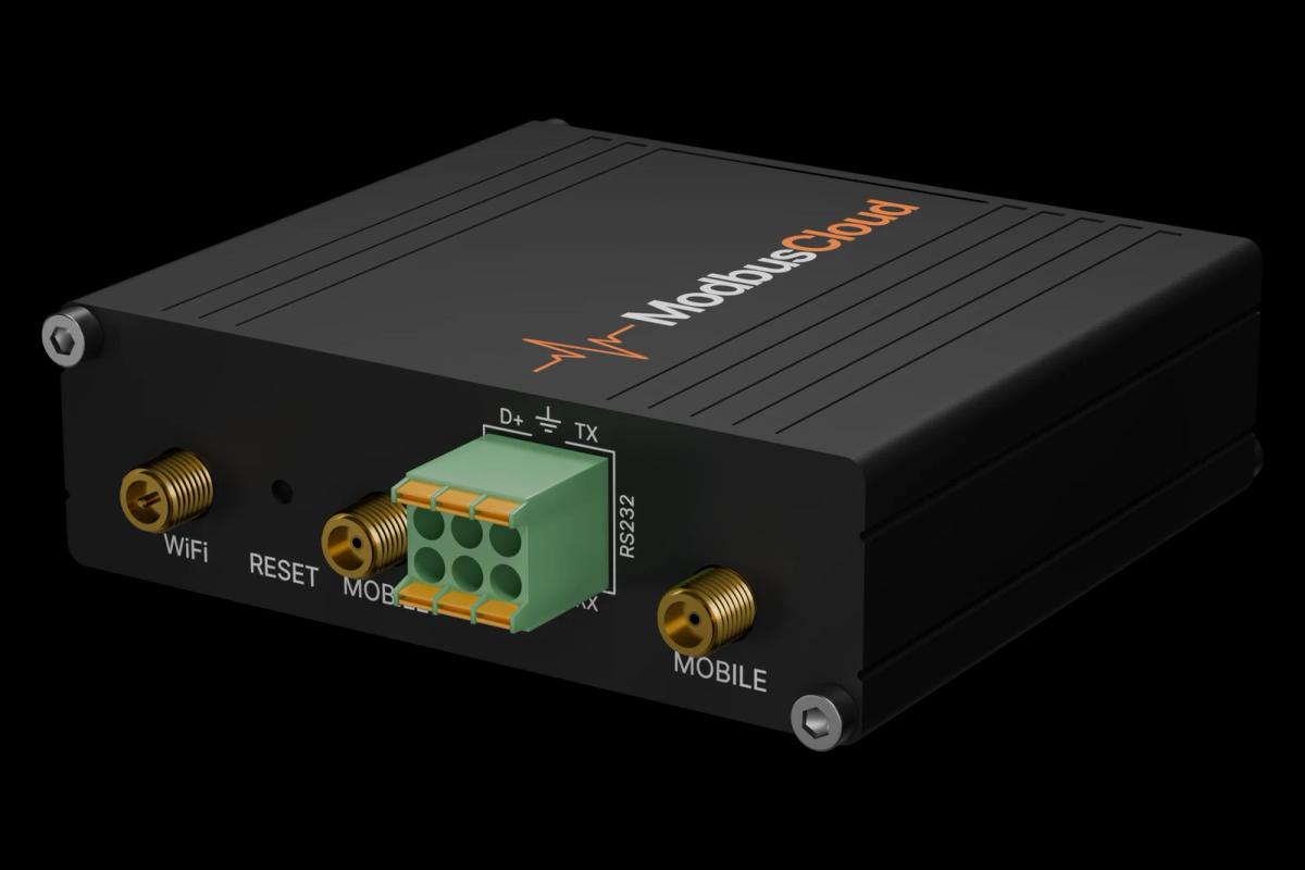
Bridge S+ to R+ and S- to R- on TB5, connect them to the RS485 port of the ModbusCloud Gateway and turn on DIP switch S2 on the last drive.
Set H5-01 to the address, H5-02 to the speed, H5-03 to the parity and H5-07 to 1, then cycle power on the drive.
For control over Modbus set b1-01 (frequency reference) and b1-02 (run command) to 2.
In ModbusCloud, add a Modbus device with the same address and settings and import this template.
Check that DC bus voltage and drive status read correct values before you write any command.
Things to watch for
The drive does not answer on the bus. What should I check?
Check H5-01 to H5-03 against the settings in ModbusCloud and cycle power after changing them. The default address is 1F hex (31). Swap R+ and R-, and check the terminator switch S2 on the last drive. A CE fault on the display means the drive saw a communication timeout.
Why does output current show odd numbers?
Register 0026H gives the current in 0.1 A. The U1-03, U2-05 and U4-13 monitors use a different scale: 8192 equals the rated current of the drive, so divide by 8192 and multiply by the rated current.
The drive ignores my run command or frequency reference. Why?
The drive only follows Modbus commands when b1-01 and b1-02 are set to 2, or when the ComRef and ComCtrl inputs are active. Check the Drive Status 1 register: bits E and F show whether the Modbus reference and run command are in control.
How do I write safely to the drive from ModbusCloud?
The drive only accepts write multiple registers. Command registers 0001H to 001FH take effect at once and start or stop the motor, so make sure nobody works on the machine. Writing must be enabled for the gateway first. The Enter command registers store parameter changes; avoid writing EEPROM often, it lasts 100,000 writes.
More Yaskawa templates


Want to see how it works?